1
72-9275: OPERATING MANUAL
Compare the readings of the tested voltages against
the said table. If the voltage is on the high side,
check the components and connectors to see if there
is anything wrong. If anything wrong is found, do
necessary service.
Charging System Voltage Testing
This testing is used to see if the charging system
operates normally so as to provide the electronic
systems with adequate power (lamps, electric fans,
radio sets, etc.).
1.
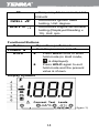
Set the rotary switch to the 200mV or 2 VDC.
As prompted at the LCD connect terminal,
insert the red test lead into the A terminal
and the black one into the COM terminal.
2.
Connect the black test lead probe to the
negative pole of the battery and the red one
to the positive pole of the battery.
3.
Run the engine idle and close or turn off all
the accessories with the normal voltage
readings being 13.2 V to 15.2 v.
4.
Open the throttle and control the rotation
speed of the engine between 1800 RPM and
2800 RPM. The voltage readings should be
consistent with those in (3) (with the
difference being no more than 0.5 V).
5.
Turn on the lamps, windshield wipers, fans
and so on to increase the load of the
electronic systems with the voltage readings
being no less than 13.0 V.
37