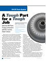
1
ServiceInsights FO R IN DEPE N D E N T SE RV I C E C E NTE R S JUL–Sep 2013 ALSO IN THIS ISSUE 2014 Impala >>Genuine GM Parts Torque Converters with EC3 are the Smart Choice >>Classics Repair Specialist Resurrects ’Vettes >>The GM Powertrain “Triple Play”—Learn More >>Look for GM at ATRA and SEMA this Fall >>Make Your Holiday Gift List Now with Genuine GM Rewards >>TechConnect Insert New from the Ground Up with Never Before Available Advanced Technologies More Inside: Impala Service Procedures CONTENTS GM OE Parts Update The latest word on product development and technologies. 4 Business of Repairs 9 New ideas that can benefit how your shop operates and profits. The Technical Side Discover new ways to approach service and repairs. 5 GM ServiceInsights Online More Genuine GM Parts resources and links. Download this issue and past issues of GM ServiceInsights magazine at... www.gmserviceinsights.com GM ServiceInsights Headquarters 2604 N.E. Industrial Dr., #230 N. Kansas City, MO 64117 Email: [email protected] Compliments of your GM dealer. We invite your input and suggestions. Please address letters to the editor to the above address. Letters submitted imply the right to edit and publish. Every effort is made to ensure the accuracy of the information in the offers contained in this magazine. However, printing and typographical errors may occur. These are not intentional and are not the responsibility of GM, any dealer or the companies or individuals who We Support Voluntary Certification create, produce and distribute this magazine. Offers and pricing may change at any time without prior National Institute for notification. The descriptions and specifications in this AUTOMOTIVE SERVICE EXCELLENCE publication were in effect at the time of approval for www.ase.com printing. General Motors reserves the right to change specifications without notice and without obligation. Published letters do not necessarily reflect the opinions of General Motors or General Motors Parts. General Motors, Detroit, MI 48202. © 2013 General Motors • All rights reserved. 2 July – Sep 2013 ServiceInsights GM Parts Powertrain Triple Play Designed around you. overPOWER Conquest pricing on many engines and transmissions. Genuine GM Rewards Rewards on your eligible GM Powertrain Parts purchases. genuinegmrewards.com genuinegmparts.com RepairLink with MORE Save time ordering GM OE parts online. oeconnection.com Genuine GM Parts . . . why settle for less? GenuineGMParts.com GenuineGMParts.com July – Sep 2013 ServiceInsights 3 GM OE Parts Update A Tough Part for a Tough Job GM EC3 Torque Convertor Genuine GM Parts Torque Converters with EC3 are the Smart Choice • Electronically Controlled Capacity Clutch material, patented by GM, expands the operating window of the converter clutch by controlling the clutch • Maintains proper heat range to prevent overheating • Improves long-term durability and fuel economy Torque converters used in GM vehicles are an especially high-tech breed built for the rigors of a demanding job. What sets them apart is GM’s Electronically Controlled Capacity Clutch. EC3, for short, incorporates special friction material that allows the converter clutch to continuously slip at low speeds. That delivers smoother shifting at a wider range of speeds, better fuel economy and less wear and tear. Just as EC3 is a smart technology, the intelligent choice for changing out a torque converter in a GM application is a Genuine GM Parts replacement assembly that uses EC3. Competing products simply don’t stack up. Typically, the friction materials they use – notably Kevlar® - generate excessive heat and don’t deliver the same smooth slip produced with the GM EC3 torque converter. “That material is durable, but the heat it generates degrades transmissions and it grabs when it engages, leading to noise/vibration/harshness issues,” says Chris Thomas, GM Customer Care & Aftersales (GM CCA) product development manager for transmissions. While there’s a big gap in performance, the issue of heat buildup is critical from a durability and longevity standpoint. In addition to using materials that produce 4 July – Sep 2013 ServiceInsights more heat, aftermarket torque converters can trap heat. That’s because unlike the Genuine GM Parts product, most come painted, Thomas says. That paint, while it may produce an attractive torque converter, can act as a barrier to heat dissipation. For nearly all GM applications beginning with model year 1999, factory-installed torque converters employ EC3. When they fail, replacing them with anything but the GM OE product is an invitation to trouble and unhappy customers. A non-EC3 torque converter will struggle to operate efficiently in a system designed for the technology. The end result is that drivers could very well detect a changed driving experience. “Aftermarket products are often one-size fits all, whereas GM torque converters are calibrated for the vehicle,” Thomas says. “For instance, they might not account for differences in stall speeds, and that might lead to vehicles with after market torque converters experiencing rollbacks on hills.” continued on page 5 continued from page 4 The Technical Side A Genuine GM Parts torque converter, the one designed for the application, is readily available through GM dealers. And now, with new pricing on torque converters, there’s even more reason to choose the OE product. Priced to be more competitive with aftermarket products, the Genuine GM Parts product will be the choice of more Independent Service Centers (ISCs). The end result: they and their customers will have the torque converter that unquestionably delivers the performance and durability demanded of this essential vehicle component. All-New 2014 Impala The 2014 Impala is new from the ground up and represents the 10th generation of one of the industry’s most enduring and popular nameplates. Three Powertrain Options, All with Six-Speeds The three powertrain options each feature fuel-saving direct injection and lightweight components. They include the 3.6L V-6, the new Ecotec 2.5L fourcylinder and the Ecotec 2.4L with eAssist. Powertrain Highlights: ˸˸Output for the 3.6L V-6 is rated at 305 horsepower (227 kW) and 264 lb.-ft. of torque (358 Nm). That is the highest horsepower output in the segment from a naturally-aspirated V-6 engine. ˸˸The Ecotec 2.5L is part of a new family of four-cylinder engines developed with increased efficiency and greater refinement. It is rated at 196 horsepower (145 kW) and 186 lb.-ft. (253 Nm) of torque The 2014 Impala delivers advanced technologies that include crash imminent braking, forward collision alert, lane departure warning, side blind zone alert, rear cross traffic alert, rear camera and rear-park assist. July – Sep 2013 ServiceInsights 5 SPECIAL INSERT The Technical Side (cont’d.) ˸˸Impala’s Ecotec 2.4L engine with eAssist provides electrical assist in certain conditions to help save fuel. It is rated at 182 horsepower (134 kW) and helps achieve estimated highway mileage of 35 mpg. The 2.4L with eAssist will be available at the end of this year ˸˸All of Impala’s engines are matched with six-speed automatic transmissions. The Ecotec 2.5L I-4 engine for the 2014 Impala features Intake Valve Lift Control technology (iVLC). iVLC allows the valves to open and close by varied amounts and at different times depending on power demand to provide greater fuel efficiency or power. Stronger, Quieter Body The 2014 Impala’s comfort and refinement are rooted in a stronger body structure, enabling a quieter passenger environment and a greater overall feeling of quality. The stiffer architecture also enabled engineers to tune the ride and handling more precisely, for a greater feeling of control and comfort. With active noise cancelation (4-cylinder models), ceiling-mounted microphones detect engine noise, the frequencies of which are processed by a computer that directs counteracting sound waves through the audio system’s speakers and subwoofer. This technology helps eliminate noise levels associated with torque converter lockup at low speeds. Engineers optimized the upper body structure shape, material, and metal gage to meet all performance Reinforced Strut Tower 6 July – Sep 2013 ServiceInsights requirements with minimal mass, and then applied the mass strategically to other areas of the vehicle. This mass savings allowed engineers to add a front strut tower reinforcement to improve structural feel. Those strut towers are home to a MacPherson-strut front suspension design that delivers a greater measure of control with rebound springs that are internal to the struts. An isolated front cradle for the engine and transmission, as well as a hydraulic ride bushing, help deliver a smoother, quieter ride. At the rear is a proven four-link suspension design, with a slightly wider track that contributes to the Impala’s more planted feel on the road. Isolated mounting provisions for the rear suspension also contribute to the car’s quiet, smooth driving experience. The Reasons for With freezing winter weather and a wet spring in many parts of the country that played havoc on road conditions, many customers may be concerned about the wheel alignment of their vehicle. Before performing a steering wheel angle/front toe set or wheel alignment check or adjustment, be sure there is nothing about the vehicle’s condition or equipment that could contribute to a misalignment condition. Things to consider include: Wheels and Tires – Verify that wheels and tires are original equipment or the correct size for the vehicle application. Slight feathering on the shoulders of tires is not considered unusual tire wear. Suspension – Verify that the vehicle suspension has not been altered, including the addition of an aftermarket suspension lift or lowering kit. Measure ride height to help identify any worn components. Vehicle Damage – Check for evidence of accidental damage that could affect alignment. Look for subtle items like scuffed wheels or tire sidewalls, which may indicate curb damage that can affect alignment. Added Equipment – Check for equipment that may significantly affect vehicle mass, such as large tool boxes, snow plows, and campers. Significant additional mass can affect the trim height and wheel alignment of the vehicle. Upfitters are instructed to realign the vehicle after installation of these types of items. It is important to gather as much information as possible to understand the customer concern, and to record complete before and after alignment measurements on the vehicle. Drive the vehicle to verify that the vehicle does have a pull condition and not a steering wheel angle issue. A vehicle with a valid pull condition will pull to one side or the other, regardless of steering wheel angle, when at a constant highway speed on a typical straight road. Always note which direction the steering wheel is clocked (left/counterclockwise or right/clockwise). When dealing with a verified steering wheel angle condition, remember that front and rear toe are the only alignment values that affect the angle of the steering wheel. IN THIS ISSUE The Reasons for Wheel Alignment . . . . . . . . 1 The Job of Magnetic Drain Plugs . . . . . . . . . 2 New Chevy HHR Interior Door Handle Kit . . 3 Absorbent Glass Mat Batteries . . . . . . . . . . . 4 Tips for Successful Brake Service . . . . . . . .. 5 ACDelco Diagnostic Hotline Offers New Flat Fee Option . . . . . . . . . . . . . . . . . . . . . 6 2013 ACDelco Fluids and Chemicals Catalog Now Available . . . . . . . . 6 Tech Tips . . . . . . . . . . . . . . . . . . . . . . . . . . . . . . 7 Training Update . . . . . . . . . . . . . . . . . . . . . . . . 8 www.acdelcotechconnect.com, click the Newsletters link Causes of Vehicle Pull A vehicle pull condition may be caused by several factors. Tires – If a pull condition has been verified but the alignment settings all are within specifications, the issue may be in the tires. Certain tire differences left to right may cause a vehicle pull. Temporarily swapping the front tires left to right and re-evaluating is a simple way to verify a tire issue. Always note if tires are directional and not able to be permanently swapped side-to-side. continued on page 3 Follow ACDelco Scan the code to download a PDF The Job of Magnetic Drain Plugs Magnetic drain plugs in drive axles, transmissions and transfer cases are designed to attract metallic particles generated during normal operation and prevent them from passing through the gears or bearings. Volume 20, Number 3 (TS-PU-0003-13) ACDelco TechConnect is published bi-monthly and online for Independent Service Centers and Key Fleet accounts to provide timely service information, increase knowledge and improve the performance of the service center. During service repairs and maintenance, inspect the drain plug for large metal deposits. Small metal flakes and fine metal dust on the plug magnet are considered normal. Fine metal particles to component operation and do not require component replacement. Normal amount of debris on a drain plug. Large metal deposits or particles on the plug magnet, such as gear teeth, bearing fragments and large metal shavings, are not a normal condition. If these conditions are found, repairs may be needed to prevent further component damage. Bearing and Gear Teeth Fragments — Fragments from bearings and gear teeth indicate component damage that is not considered normal. Components should be inspected for damage and repaired as needed. Fluid Conditions What to Look For When inspecting metallic particles on a plug magnet, it’s important to determine the size and source. Fine Metal Particles — Fine metal particles are normal and are the result of internal component wear, which can shed fine metallic particles at a steady rate. Metal Shavings — Metal shavings, which are often remnants from the housing machining process, may adhere to the plug magnet. These shavings are not detrimental Publisher: Rick Balabon ACDelco E-mail [email protected] Editor: Greg St. Aubin ACDelco E-mail [email protected] The color of the fluid can be an indicator of contamination; however, some colors can be easily confused with the normal color of some fluids. Technical Editor: Mark Spencer E-mail [email protected] New fluid is usually red or light brown. With time and miles, used fluid often turns black. This is a result of the normal chemical process that occurs as the additive package in the fluid degrades. The black color does not indicate that the fluid’s useful life has been exhausted. Production Manager: Marie Meredith When a fluid is a milky brown color, it may indicate that the fluid is contaminated with significant moisture. The fluid should be changed. An abnormal amount of debris with large metal shavings on a drain plug. ACDelco 360 represents our mission to look at our businesses at every possible angle to provide value and assistance to our distributors and their customers as well as offer a full circle of support with programs, tools, training and marketing focused on enhancing and growing our partnership successfully. Water contamination of the axle lube also creates significant odor and forms corrosive conditions that will cause internal components of the axle to corrode. Milky-colored fluid combined with rust particles is a sign of moisture contamination either from submersing the axle vent, a pinched or misrouted vent hose, or a failed seal that is allowing moisture to enter the axle. Under 5000 miles (8,000 km) of operation, hypoid axle lube may appear tinted and have a whitish or yellow appearance from the gear marking compound used in the production of the axle. – Thanks to Dave Peacy and David MacGillis 2 Tech Connect Desktop Publishing: 5by5 Design LLC E-mail [email protected] Write to: ACDelco TechConnect P.O. Box 500 Troy, MI 48007-0500 On the Web: To read or print recent issues of TechConnect: – www.acdelcotechconnect.com, click the Newsletters link. ACDelco service tips are intended for use by professional technicians, not a “do-it-yourselfer.” They are written to inform those technicians of conditions that may occur on some vehicles, or to provide information that could assist in the proper service of a vehicle. Properly trained technicians have the equipment, tools, safety instructions and know-how to do a job properly and safely. If a condition is described, it cannot be assumed that the information applies to all vehicles or that all vehicles will have that condition. All materials and programs described in this magazine are subject to change. Submission of materials implies the right to edit and publish. Inclusion in the publication is not necessarily an endorsement of the individual or the company. TechConnect is published for ACDelco by Sandy Corporation, Troy, MI. ©2013 ACDelco. All rights reserved. The Reasons for Wheel Alignment – continued from page 1 Plus, always ensure tire pressures are set to correct specifications before and after evaluating a vehicle. Alignment Settings – Front or rear toe values being out of specifications do not cause an otherwise true vehicle pull. If only front or rear toe values are out of specification on a vehicle with a confirmed pull issue, something else is causing the pull. Steering Calibrations – Electronic Power Steering (EPS) steering position and torque sensors that are not calibrated correctly may cause a lead or pull condition. Prior to any measurement on an alignment machine, confirm the current specifications and tolerances in the appropriate Service Information. Do not assume the numbers in the alignment machine are correct and up-to-date. The vast variation in specifications, depending on the type of vehicle and tire, suspension and engine options, makes it easy to use the wrong wheel alignment specs. It is possible for customers to confuse a steering wheel off angle Verify lead/pull conditions condition as a vehicle pull condition, as they may be trying to hold the wheel centered (level) on a straight road, which would be adding a slight steering input to the wheels. Road Conditions Road Slope – High road slope angles can cause a vehicle to drift one way or the other. Use a road that is as flat as possible for evaluations. Trough Wander/Tramlining – Troughs or grooves in the road can pull a vehicle to one side or the other, depending on where the tire is located in the groove. The tires will always want to pull the vehicle up the wall of the trough. Effect of trough wander Vehicles with low aspect ratio, wide tires tend to be more sensitive to this condition. Adjusting alignment settings will not improve a trough wander condition or the sensitivity of the vehicle to trough wander. To review all of GM’s standard wheel alignment service procedures, refer to Bulletin #05-03-07-009. For an overview of wheel alignment procedures, check out the online ACDelco Wheel Alignment training course, S-SS04-05.01WBT. – Thanks to Rick Balabon New Chevy HHR Interior Door Handle Kit Instead of either replacing an entire door trim panel on a Chevrolet HHR that comes with the door handle pocket assembly, or replacing just the assembly, GM offers a new HHR Door Handle Kit that makes it possible to replace only the door handle, an economical alternative to the previous handle replacement strategy. Door handle kit The interior door handle replacement kit installs quickly and is less likely to compromise trim panel integrity and cosmetics than the alternative repair methods. The kit is available for righthand doors (part number 19299613) and left-hand doors (part number 19299614). Other aftermarket products may call for replacing the modular designed door handle pocket with a new one, which involves drilling away the melted area of five plastic stakes that attach the handle pocket to the trim panel assembly, removing the entire pocket, and attaching the new assembly by gluing metal trim screws into the heatstaked plastic areas. The pocket assembly on the HHR door is not designed for removal and the addition of trim screws in the heat-staked plastic studs may leave marks on the trim panel’s exterior surface. The interior door handle replacement kit involves a simple three part 3 Tech Connect Interior trim panel kit: a door handle, pin and spring. After removing the interior trim panel, pull the pin to remove the damaged handle. The new handle, pin and spring are installed into the modular door handle pocket. This quick and easy repair makes the new HHR inside door handle kit more economical than replacing the entire door panel. – Thanks to Rick Balabon Absorbent Glass Mat Batteries Up until the Absorbent Glass Mat (AGM) battery was introduced, automotive starting batteries always contained lead plates submerged in liquid electrolyte. The AGM battery eliminates the need to immerse the plates. The result is a battery that is lighter (a critical aspect with today’s increasing focus on fuel economy) for the amount of power it can produce. It’s also more durable in many applications and has extended life when compared to a traditional flooded-cell battery. Currently, an AGM battery is standard equipment in the Chevrolet Volt and Cadillac ATS. ACDelco offers an AGM battery for many applications as well as a special EREV (Extended Range Electric Vehicle) AGM battery for the Volt. The time required to charge a battery will depend upon the battery charger capacity, the state of charge of the battery (a discharged battery with a voltage below 11 volts will have a very high internal resistance and may only of the battery and battery capacity. Use a taper-rate charger that reduces the charging rate as the battery approaches full charge, then stops the charge or switches to a float charge status when full charge is reached. In addition, when load testing an AGM battery make sure to connect the tester directly to the battery and not to the remote connection under the hood. The AGM battery may be used in place of a conventional battery. Just be sure to match the Cold Cranking Amp (CCA) and Reserve Capacity ratings. Inside the Battery The AGM battery has a lifetime supply of electrolyte in its contact with the lead plates. The chemical reaction that takes place between the sulfuric acid in the electrolyte and the lead oxide in the lead plates create the electrical flow. The sealed AGM battery also uses gas recombinant technology that causes the hydrogen and oxygen byproducts — two natural byproducts that are produced when water in the electrolyte decomposes during charging — to convert directly back into water so the absorbed electrolyte replenishes itself. The battery does not have any vent plugs. It may have up to six vent relief valves that allow the small amount of gas that is produced when charging to escape. Testing and Charging properly to charge an AGM battery, including selecting the proper battery type, AGM setting, and CCA during charger set up. Selecting the wrong type of battery and CCA could cause misdiagnosis and/or overcharging of the battery, which could lead to inadvertent battery replacement or battery damage. directly to the battery if the battery is accessible. If the battery is not accessible, such as a dead battery and the cargo area cannot be opened, it is OK to charge or jump-start the vehicle from the remote access area under the hood as amps is not exceeded by the charging device. – Thanks to John Munsell Testing and charging the AGM battery is different from regular lead acid batteries. ASE Test Prep Study Guides Available ASE test prep study guides are available through the ACDelco Learning Management System (LMS) on www.acdelcotraining.com. The study guides cover the Automotive Tests (A1-A8), the Service Consultant Test (C1), Compressed Natural Gas Vehicle Test (F1) and Exhaust Systems Test (X1). To access the study guides, perform a catalog search on the ACDelco LMS. Select Course Name contains “ASE” and the Course Delivery Type of Self Study. We Support Voluntary Certification National Institute for AUTOMOTIVE SERVICE EXCELLENCE www.ase.com To register for ASE tests, go online to www.myASE.com or call the ASE testing partner, Prometric, at 1-977-346-9327. —Thanks to Greg St. Aubin 4 Tech Connect Tips for Successful Brake Service The keys to a successful brake service involve making the right call on rotor proper assembly. The result: a brake service that leaves the rotors with plenty of life and without unacceptable noise. Brake Noise Some brake noise is normal and differences in loading and driving style can affect brake wear. Inspect all metalto-metal contact areas between pads, pad guides, calipers and knuckles, which should be clean and lubricated with a thin layer of high temperature silicone grease (use ACDelco Silicone Brake Lubricant, part number 88862182). The lubricant, when applied to the back of each pad, acts as a brake dampening compound that allows parts to slide freely and not vibrate when moving relative to each other. tion stamped on the rotor is the minimum thickness and not the discard speciReplace the rotors if they do not meet the minimum thickrotors. lathe equipment is properly calibrated. bly to be offset when mounting, which creates vibration similar to a tire with high Radial Force Variation or a tire with an imbalance. Improper torque also may cause brake rotor distortion and result in wheel mounting variance, causing smooth road shake vibration. rotor by sanding both sides of the rotor sandpaper for about one minute per side. Cleaning Brake Rotors after Refinishing GM now recommends washing brake ing. It has been determined that soap and water, such as a mild dish washing soap, is more effective in cleaning rotors than using denatured alcohol or approved brake cleaner. ACDelco Silicone Brake Lubricant The following noises may be normal characteristics of a braking system and do not indicate improper operation. front semi-metallic brake pads at medium speeds when light to medium pressure is applied to the brake pedal. brakes and some front disc brakes during initial stops after the vehicle has been parked overnight. This is caused by corrosion on the metal surfaces during vehicle non-use. until there is enough contact to provide resistance and complete the torque to If the brake rotors are not thoroughly other noises may occur due to residual — being present on the brake rotor. Before reassembly, clean all brake corner mating surfaces, including the hub, rotor and wheel. Wheel Torque Inappropriate wheel torque methods may cause the wheel and tire assem- Do not use torque sticks or an impact driver to tighten the wheel lug nuts. Brake Pad and Rotor Burnishing Burnishing the brake pads and rotors helps to ensure that the braking surfaces are properly prepared after service has been performed. The burnishing procedure should be performed whenevor replaced, and/or whenever the brake pads have been replaced. 1. Select a smooth road with little or apply the brakes to bring the vehicle to a stop. Do not allow the brakes to lock. stopping quickly or moving forward slowly from a complete stop. During hard braking applications, this noise is a normal function of the anti-lock brake system activation. - Rotor Refinishing in the appropriate Service Information. - For proper wheel installation, index the tire and wheel assembly at least two stud positions from the previous position. Tighten the wheel lug nuts using an appropriate torque pattern. Index the tire and wheel assembly, use an appropriate torque pattern, and torque the lug nuts to spec using a torque wrench. 5 Tech Connect periods between stops in order to properly burnish the brake pads and rotors. – Thanks to Rick Balabon Professional Service Center ACDelco Diagnostic Hotline Offers New Flat Fee Option Have a tough or unusual service repair on any make or model, foreign or domestic, including medium-duty trucks? Call the ACDelco Diagnostic Hotline for help. With their new Flat Fee Unlimited Call option, technicians can call regarding a repair on one vehicle as many times as needed. Plus, the ACDelco Diagnostic Hotline still offers the economical per minute call rate. Unlimited Calls for $35 Just introduced, the Flat Fee Unlimited Call option is available for $35 per case. After the first call, all additional calls on the vehicle are free until the case is closed. In addition to the flat fee option, ACDelco Professional Service Centers (PSC) still can choose to receive the discounted call rate of $2.85 per minute (the first 10 minutes for any new PSC account are free). Making the call to the ACDelco Diagnostic Hotline is easy and hasslefree. There is no charge for preliminary information. The clock starts when you start troubleshooting with the technical expert. For particularly difficult issues, you can request schematics via fax or email. The experts at the ACDelco Diagnostic Hotline can offer live assistance on any service issue. These experts: • Are specialists by make (all makes and models) • Have an average of 25 years service experience • Are continually updated with the latest training on new systems and components • Have the latest factory information available, including direct access GM OEM Service Information Additionally, if you desire to re-bill your customer, you may request an invoice for the cost of the call, including a mark up if desired, to attach to your customer’s statement. The ACDelco Diagnostic Hotline can be reached at 1-800-825-5886, prompt #2. Provide your ACDelco Professional Service Center six digit account number when calling. – Thanks to Jill Brown 2013 ACDelco Fluids and Chemicals Catalog Now Available The new catalog includes a Service Event Quick Reference Guide that highlights common automotive service events — such as engine service, brake service, drive line service — and the associated ACDelco fluid and chemical products. It also features a section on GM Recommended Fluids at GM Recommended Intervals, which provides information about the uses of a variety of ACDelco fluids and lubricants. The catalog covers a variety of fluids and chemicals, including: • Adhesives • Air Conditioning • Antifreeze/Coolants • Appearance ACDelco has recently released the new 2013 ACDelco Fluids and Chemicals Catalog, item number VC-CA-0304-12A. • Axle Lubes/Fluids • Body Shop • Brake Cleaners and Fluids 6 Tech Connect • Carb/Choke Cleaner • Diesel Exhaust Fluid • Fuel System • Lubricants/Greases • Motor Oils • Paints • Power Steering Fluids • Sealants • Transmission Fluids Additional hard copies of the catalog (VC-CA-0304-12ACD) can be ordered through the ACDelco e-Store at acdelcoestore.com. Electronic copies of the catalog (VC-CA-0304-12E) and oil supplement (10-SU-0305-12E) also can be downloaded from the ACDelco e-Store. – Thanks to Don Vogrin TechTips The following technical tips provide repair information about specific conditions on a variety of vehicles. If you have a tough or unusual service repair, the Diagnostic Hotline can help. Call 1-800-825-5886, prompt #2, from 8 a.m. to 8 p.m. ET Monday–Friday, to speak with a technical expert with the latest OEM information. Installing the Rear Window to the Window Regulator Assembly • Multiple warning MILs illuminated After removal of a rear door window or rear window regulator on 2008-2012 Malibu, 2008-2009 G6 and 2007-2009 AURA models, the retaining pins may be difficult to reassemble in the door. The diagnostic system check may reveal that one or more DTCs are stored. The TCM or ECM may not communicate with the scan tool. The cause may be unseated pins in the transmission connector. Follow these steps to reinstall the window glass to the regulator: 1. Remove the window from the door. 2. Position the window glass retaining pin in the window hole. Make sure the pin is centered in the opening. 3. Press the expansion pin back into the retaining pin. This will lock the pin into position in the window. 4. Reinstall window into the door. 5. Push the window and pin down into the groove of the window regulator. A loud audible snap should be heard, which confirms the window assembly is properly seated in the window regulator assembly. • Transmission shifts hard • Door locks cycle while driving Inspect the transmission connector X1 terminal connections. Disconnect the connector and carefully tug on each wire to ensure the pins are fully seated. A side load on the wires may cause a false positive lock. Repair the connections as necessary. Cold Engine Tick Noise 2009-2013 Cadillac Escalade models; 2009-2013 Chevrolet Express, Silverado, Suburban; 2009-2013 GMC Savana, Sierra; equipped with a 6.0L or 6.2L V8 engine (RPO L76, L96, LY6, L94, L9H) A cold engine tick noise may be heard on these vehicles. The noise will diminish within 50 seconds of a cold start. The noise shuts off like a switch was flipped. This condition may be a vehicle design characteristic as the ECM calibration is designed to meet cold start emissions. The noise that is heard is actually combustion taking place in the exhaust manifold. When the timer hits the 50 seconds it advances the timing and the noise is immediately gone. No Crank, Transmission Shifts Hard 2013 Cadillac ATS; 2008-2013 Cadillac CTS; 2007-2009 Cadillac SRX; 2006-2011 Cadillac STS; equipped with a 6-Speed Automatic Transmission One or more of the following conditions may be present: • Service Engine Soon light on • Reduced power • The vehicle will not crank over, no start Be sure to determine if the tick noise is possibly coming from the exhaust manifold, as the noise could easily be mistaken for an engine tick noise. Programming the Vehicle Theft Deterrent 2006-2013 Chevrolet Impala; 2006-2007 Chevrolet Monte Carlo If the Theft Deterrent Module (TDM) and ECM are replaced at the same time or, if during service, the theft deterrent becomes unsynchronized, the theft deterrent must be synchronized in order for the vehicle to start. 7 Tech Connect Depending on the state of the theft deterrent, the vehicle may have a no crank, no start condition, or a crank, start and stall condition. If the ECM and TDM are replaced at the same time, reinstall the original ECM or the original TDM, if possible. Communication must be established with the original ECM or TDM. Next, service program the original module (ECM or TDM) and perform a 10 minute Vehicle Theft Deterrent learn. If it is still necessary to replace the ECM or TDM, replace it. At this time, the ECM or TDM and key are synchronized. Service program the new ECM or TDM and perform a 10 minute Vehicle Theft Deterrent learn. If neither the original ECM nor TDM is available or will not communicate, it will be necessary to also replace the ignition keys. If you attempt to program the new ECM or TDM using the original ignition keys and the vehicle will not start, check the Manufactures Enable Counter in the TDM ID information. If the Manufactures Enable Counter display is blank, the TDM has been programmed. If the counter reads a value other than zero, the TDM needs to be programmed. Product Information For free technical assistance and product information regarding specific ACDelco products, contact these tollfree information hotlines staffed by ASE-certified technicians: Brakes – 1-888-701-6169 (prompt #1) Chassis – 1-888-701-6169 (prompt #2) Clutches – 1-888-725-8625 Lift Supports – 1-800-790-5438 Shocks – 1-877-466-7752 Starters and Alternators – 1-800-228-9672 Steering (Pumps, Rack and Pinion, Gears) – 1-866-833-5567 Wiper Blades – 1-800-810-7096 TrainingUpdate 2013 Training Course Catalog Available Technical course categories include: Business training includes: A0: Fundamentals/Emerging Technologies • Service Consultant Skills The 2013 ACDelco Training Course Catalog is now available. A1: Engine Repair • Customer Satisfaction Process A2: Automatic Transmission/Transaxle • Financial Management A3: Manual Drivetrain and Axles • Marketing The catalog provides course descriptions for ACDelco Web-Based Training (WBT) courses, Instructor-Led Training (ILT) courses and Seminars (SEM) along with related training in Self-Study Training (SST), Tech-Assist (TAS), and Virtual Classroom Training (VCT) formats. A4: Suspension and Steering Download the 2013 ACDelco Training Course Catalog by visiting www.acdelcotechconnect.com and clicking the Training tab or logging in to the ACDelco Learning Management System (LMS). A5: Brakes A6: Electrical/Electronic Systems A7: Heating and Air Conditioning A8: Engine Performance New Courses The latest ACDelco training courses cover many different topics ranging from HVAC systems to bi-fuel systems and electrical systems. Some of the new course releases include: Course Number S-AC07-08.02WBT S-AC07-09.02WBT S-DS11-11.01SEM S-EL06-52.02WBT Course Name HVAC Systems and Operation Stage 1 HVAC Systems and Operation Stage 2 Beyond the Four Strokes: What do you do when nothing you see is wrong but something is broken? GM Global Electrical Systems Course Number S-EP08-08.02ILT Course Name Evaporative Emissions Controls: Why is there always a code but never a leak we can find? Spark Generation: Is a lack of spark sending you up in flames? Bi-Fuel System Operation GM Safety Systems 3 S-EP08-09.01ILT S-EP08-29.01WBT S-FN00-07.01WBT How to Take ACDelco Training Go to www.acdelcotechconnect.com and click the Training tab to log in to the ACDelco Learning Management System (LMS). • To enroll in courses in your training path , open the home page to view your Training Progress Status Report, select Click Here to Show Detail, and then click the course number and title to view details on a specific course and to launch or enroll in the course. • To enroll in an Instructor-Led Training (ILT) course (ILTs are full-day hands-on classroom courses), click Take Training > Instructor-Led Training to view the catalog and select a specific course. • To enroll in a Virtual Classroom Training (VCT ) course (VCTs are 1-2 hour live online courses), click Take Training > Virtual Classroom Training to view the catalog and select a specific course. • To launch a Web-Based Training (WBT) course (WBTs are 1-4 hour self-guided online courses), click Take Training > Web-Based Training to view the catalog and select a specific course. • To launch a TechAssist (TAS) course (TAS courses are 15-20 minute online presentations on a specific topic), click Take Training > TechAssist to view the catalog and select a specific course. • To launch a Simulation (SIM) (SIMs require users to complete all repairs for a condition), click Take Training > Simulations to view the catalog and select a diagnostic challenge simulation. Training Schedule To search for currently scheduled courses in your area, view the Training in Your Area section on the Home page. Select search terms from the dropdown menus and click the Submit button. Current Instructor-Led Training Courses The following ILT courses are currently being scheduled: Course Number S-AC07-02.01ILT S-AC07-03.01ILT S-BK05-01.01ILT S-BK05-02.01ILT S-DS11-13.01ILT S-EL06-04.02ILT S-EL06-10.02ILT S-EL06-11.02ILT S-EL06-13.01ILT S-EL06-14.01ILT Course Name Automotive Air Conditioning Advanced Refrigerant System Diagnostics HVAC Control System Operation and Diagnostics Braking Systems ABS Operation and Diagnosis Vehicle Network Communications: When modules talk, who is really listening? Network Communication Diagnosis Electrical Power Management Enhanced Automotive Circuit Diagnosis Body Electrical Global Diagnostics Advanced Body Control System Electrical Diagnostics Course Number S-EL06-16.01ILT S-EP08-02.01ILT S-EP08-03.01ILT S-EP08-04.01ILT S-EP08-06.01ILT S-EP08-08.02ILT S-EP08-09.01ILT S-EP08-81.02ILT S-SS04-01.01ILT 8 Tech Connect Course Name Hybrid Vehicle Service and Safety: Batteries Included Engine Performance Computer Controls and Ignition System Diagnostics Engine Performance Air Induction and Fuel System Diagnostics Engine Performance Fault Monitoring and Emission System Diagnostics After Combustion Sensors: Is what is in the exhaust making your engine run rough? Evaporative Emissions Controls: Why is there always a code but never a leak we can find? Spark Generation: Is a lack of spark sending you up in flames? Duramax Diesel Operation and Diagnosis Vibration Correction Diagnostics The Technical Side (cont’d.) Even though the 2014 Impala is a new vehicle, service and repair information resources are a click away at www. gmtechinfo.com — Electronic Service Information. Technicians and shop owners can log on to the site to gain access to subscription services for service procedures and repair manuals. A complete Service Manual is accessible 24/7 through a subscription to the site. Free collision repair procedures will soon be available for the vehicles by going to www.genuinegmparts.com. Starter Replacement for the Ecotec 2.5L I-4 engine (LKW), 2014 Impala Installation Procedure Removal Procedure 1 1 2 Disconnect the battery negative cable. Refer to Battery Negative Cable Disconnection and Connection. Remove the secondary air injection pump, if equipped. Refer to Secondary Air Injection Pump Replacement. 4 5 Remove the battery positive cable fastener (2) and remove the battery positive cable terminal (1), from the starter solenoid. 6 Remove the starter mounting fasteners (2) and remove the starter (1). Install the starter (1) and torque the top fastener (2) to 22 Y (16 lb ft), then torque the bottom fastener (2) to 22 Y (16 lb ft). 1 Install the battery positive cable terminal (1) to the starter solenoid and tighten the fastener (2) to 10 Y (89 lb in). Raise and support the vehicle. Refer to Lifting and Jacking the Vehicle. Disconnect the engine harness connector (3) from the starter solenoid. Caution: Refer to Fastener Caution. 2 3 4 Caution: Refer to Starter Motor Alignment Caution. 3 6 2 Install the engine wiring harness connector (3) to the starter solenoid. 4 Install the secondary air injection pump, if equipped. Refer to Secondary Air Injection Pump Replacement. 5 Connect the battery negative cable. Refer to Battery Negative Cable Disconnection and Connection. WE’VE GOT ALL THE PARTS YOU NEED TO DO IT RIGHT, THE FIRST TIME! If you’re doing a powertrain repair procedure, remember that we’ve got all the parts you need — cylinder heads, actuator motors, electrical, pulleys and tensioners, gaskets — whatever you need to keep your customers happy . . . and coming back. July – Sep 2013 ServiceInsights 7 The Technical Side (cont’d.) Generator Replacement for the Ecotec 2.5L I-4 engine (LKW) in the 2014 Impala 6 1 2 1 2 8 Remove the secondary air injection pump inlet hose, if equipped. Refer to Secondary Air Injection Pump Inlet Hose Replacement. 4 9 8 9 Remove the lower generator mounting fastener (2). Remove the upper generator mounting fasteners (1) and secondary air injection pump inlet hose bracket, if equipped. 10 8 Remove the generator (1) from the engine compartment. July – Sep 2013 ServiceInsights Install the battery positive cable (3) to the back of the generator and tighten the fastener (2) to 15 Y (11 lb ft). Install the protective boot (1) and connect the engine wiring harness connector (4). Remove the protective boot (1) and the battery positive cable fastener (2). 7 2 5 Raise and support the vehicle. Refer to Lifting and Jacking the Vehicle. Remove the battery positive cable terminal (3) and the engine harness connector (4) . Install the generator lower mounting fastener (2) and tighten to 22 Y (16 lb ft). Install the air cleaner outlet duct. Refer to Air Cleaner Outlet Duct Replacement. 3 Remove the drive belt. Refer to Drive Belt Replacement. 1 3 Remove the air cleaner outlet duct. Refer to Air Cleaner Outlet Duct Replacement. 4 5 6 Caution: Refer to Fastener Caution. Note: Position the secondary air injection pump inlet hose bracket to the generator (LCV Engine), if equipped. Install the generator (2) into position and tighten the fasteners (1) to 22 Y (16 lb ft). Removal Procedure Disconnect the negative battery cable. Refer to Battery Negative Cable Disconnection and Connection. Installation Procedure 10 4 6 7 Install the drive belt. Refer to Drive Belt Replacement. Install the secondary air injection pump inlet hose, if equipped. Refer to Secondary Air Injection Pump Inlet Hose Replacement. These examples of Starter and Generator Replacement for the Ecotec 2.5L I-4 engine (LKW) in the 2014 Impala are just two of many found in their Service Repair Manuals. By following the proper repair procedures, technicians can ensure that each vehicle maintains its solid performance and uncompromised safety features for the life of the vehicle. The Business of Repairs Dynamic Duo Delivers Chevrolet Performance Parts Helps Washington ‘Vette Specialist Resurrect Classics When a 1997 Corvette owner started feeling a little power- and status-starved with his well-worn stock LS1 engine, his instincts brought him to the right place. Two of them, actually: Corvettes of Auburn and Chevrolet Performance. For folks in the Seattle area and beyond wanting to spruce up and juice up their Corvettes or other prized set of wheels, there are few destinations better primed to deliver than Corvettes of Auburn. Operating out of the Seattle suburb of Auburn for the last 20 years, Dan Tumia, owner, has built a reputation across the Pacific Northwest as a man to see for quality restorations and repowering. Chevrolet Performance, a brand Tumia is well-versed in, was the owner’s second great call. Staying in the GM family, he selected an LS3 376/480 Hot Cam engine as the successor to his LS1, which had faithfully logged some 130,000 miles. The combination of the powerful small-block V-8 engine, combined with Corvettes of Auburn’s expertise in handling the trickiest repowering jobs, proved to be a winner. Today, that owner has the best of both worlds: a priceless C5 Corvette whose stock LS1 broke new ground when it was new, now fully up-to-date under the hood with today’s state-of-the-art premium Corvette engine. “He wanted more power and the drive train beefed up with new and improved parts,” Tumia says. “The LS3 Hot Cam crate performance motor comes with everything from fuel injectors to the oil pan, but without some of the bolt-on hardware on the front like the serpentine belt and the alternator. For the most part, most everything from the original LS1 transferred easily over to the LS3.” One challenge was relocating the knock sensors. “On the new engine we had to position the existing boss that was used for the LS1 back to where it was,” Tumia says. Vacuum lines also had to be rerouted, a challenge, he says, because the conversion entailed going from a return to a non-return system. “It would recycle through the fuel pump and not back to the engine, so we had to modify the fuel return line to make that fit,” he says. Radiator hose configurations also posed a challenge. With the water pump inlets and outlets in different spots on the radiators in the LS1 and LS3, Tumia had to devise a custom ized fix that would work in the new engine configuration. July – Sep 2013 ServiceInsights 9 The Business of Repairs (cont’d.) A customer’s ’97 ’Vette gets an LS3 upgrade at Corvettes of Auburn, Auburn, Wash. Tumia also had to contend with some pilot bearing issues. “When we went to put the torque tube into the pilot bearing we came up 1/16-inch short, so we used bolts to pull it up snug and flush, “he says. “We started the car up and ran it a bit before putting on the dyno and we heard a noise coming from the clutch. We pulled everything out, looked at the pilot bearing again and we were shaking our heads trying to figure out what we did wrong. Turns out that the torque tube input shaft was for the LS1, not the LS3 and so it was deeper into the crankshaft. We ended up beefing up the torque tube, and we used a solid coupling rather than a stock rubber one for a device that links the back of the engine to the clutch.” Dan Tumia, owner, Corvettes of Auburn, Auburn, Wash. Tumia also encountered some issues with crankshaft positioning. The crank trigger, which with the help of the power control module, reads the crankshaft position, was different on the LS1. “The crankshaft position gear in the LS1 has different amount of teeth on it than the LS3, so using the LS1 PCM we needed a go-between that would divide out the number of teeth on the wheel so the LS3 computer could read it,” he says. Moving from a stock throttle body on the LS1 to a larger one for the LS3 presented another challenge. The on-board computer in the LS3, Tumia says, was detecting “way too much air, so we had to consider that when we remapped the PCM.” In the end, Tumia’s customer got what he was seeking. Outfitted with new headers, a new clutch, a stiffened up 6-speed transmission, and an aftermarket interface to rectify the crank trigger issue, the Vette was dyno-tuned to deliver 428 horsepower and 421 lb.-ft. of torque at the wheels, yielding a final reading of approximately 496 horsepower and 488 lb.-ft. of torque. “It runs strong and has some real nice lope to it,” he says. A 35-hour job, the project was typical of the ones Tumia has learned to do almost in his sleep over the years. Some of that credit goes to Chevrolet Performance products. Those products, he says, are just what many of his customers are looking for: engines easily installed but able to deliver the punch they want to extend the lives of their prized vehicles. “We get a lot of customers coming in with cars that may not be worth much — older C4s and C3s — but that are driven hard, and they’re looking to bring back the luster of days gone by.” Tumia, of course, is happy to oblige. LS3 Crate Engine in the shop, Corvettes of Auburn, Auburn, Wash. 10 July – Sep 2013 ServiceInsights Start Your Holiday Gift List NOW! Earn reward points with purchases of GM Engines, Transmissions and Powertrain Component Parts. Contact your GM dealer for details, or go to www.genuinegmparts.com See you at Please visit General Motors at Booth #23743 at the 2013 SEMA Show, Nov. 5–8, Las Vegas Convention Center. Make Plans for ATRA Please visit Genuine GM Parts at Booth #212. The 2013 ATRA Show takes place Sept. 19-22 in Washington DC at the Washington Marriott Wardman Park Hotel. July – Sep 2013 ServiceInsights 11 We’re your one stop for all the GM Engine, Transmissions and Powertrain Components you need. CLIP AND PLACE BY YOUR TELEPHONE OR COMPUTER Give us a call for all of your Genuine GM Parts needs — all at one convenient location.