1
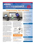
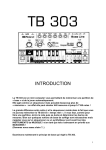
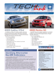
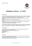
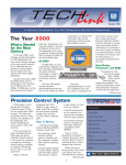
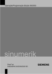
April 2010
Volume 12, No.4
Corroded or stripped electrical ground
connections can cause a loss of module
communication and other electrical
system malfunctions, leading to unnecessary repairs and parts replacement.
The electrical system relies on a secure,
corrosion-free ground connection in order
to function properly, so any damaged
ground connections must be repaired to
provide a good mounting point with a
low resistance ground path and prevent
future corrosion.
GM recently released a new bulletin
covering electrical ground connection
repairs. Refer to bulletin #10-08-45-001
for complete repair and installation
instructions. Here are the highlights.
The bulletin outlines ground repair
procedures using one of the following
replacement fasteners with a conductive
finish:
• Welded M6 stud and nut
• Welded M6 nut and bolt
• Welded M8 nut and bolt
Before installing a new fastener in the
current ground location or at a new
mounting location, remove any grease
TIP: The surrounding area must be
properly finished prior to the installation
of the ground wire terminal and conductive nut to maintain a secure, stable and
corrosion-free electrical ground.
Thoroughly clean the stud threads
using a residue-free solvent. Once dry,
apply dielectric lubricant to the threads to
reduce the possibility of fretting.
TIP: Fretting corrosion is a build-up of
insulating, oxidized wear debris than can
continued on page 2
M6 conductive rivet stud
from the repair area using a residue-free
solvent.
After drilling the mounting hole (for a
new location), remove any paint and
primer from the area until bare metal
is visible.
Install the appropriate new fastener
and check that it is securely fastened
without any detectable movement.
Cover the stud threads with protective
material and refinish the repair area
using an anti-corrosion primer.
SPO Changes Name to
Customer Care and Aftersales
GM recently announced that the Service Parts Operations (SPO) organization
will now be known as GM Customer Care and Aftersales. It includes GM
Service Operations, ACDelco, GM Goodwrench and GM Performance Parts.
The name change was made to better reflect GM’s renewed emphasis on
customer satisfaction and service after the sale.
– Thanks to Lisa Scott
April 2010
Contents
Electrical Ground Repairs . . . . . . . . . . . . .
SPO Changes Name to Customer Care
and Aftersales . . . . . . . . . . . . . . . . . . . . .
Installing Replacement Rear Leaf Spring . . .
Various Electrical Conditions . . . . . . . . . . .
Intermittent Service Park Assist Message . .
Control Module Programming
and Setup Procedures . . . . . . . . . . . . . . .
Global A Architecture Programming Tip . . .
2010 Wheel Nut Torque Specifications . . . .
Owner Manuals Available in SI . . . . . . . . . .
New Battery Electrical Drain/Parasitic Load
Test Diagnostic Procedure . . . . . . . . . . . .
Subscribe or Unsubscribe to
Paper Service Bulletins . . . . . . . . . . . . . . .
2010 Two-Mode Hybrid System Changes . .
Power Steering Hose Retrofit Procedure . . .
EBCM and BPMV Parts Restriction . . . . . .
Properly Locking the Roof Rack Cross Rails .
No Retained Accessory Power
after Radio Replacement . . . . . . . . . . . . . .
Inoperative Power Liftgate . . . . . . . . . . . . .
Heated Seat and PPS Module Kit . . . . . . . .
Car Issues – Fix It Right the First Time . . . .
Truck Issues – Fix It Right the First Time . . .
Service Know How . . . . . . . . . . . . . . . . . .
.1
.1
.2
.2
.2
.3
.3
.4
.4
.5
.5
.5
.6
.6
.6
.7
.7
.7
.8
.8
.8
Customer Care and Aftersales
1
Electrical Ground Repairs
Installing
Replacement Rear
Leaf Spring
–
continued from page 1
form when there is a
small motion between
electrical contacts,
causing electrical
resistance across the
connection.
Remove any corrosion or contamination
on the electrical
ground wire terminal.
Install the terminal,
tighten the conductive
nut to the proper
torque and verify
system operation.
Refer to the bulletin
for a list of part
numbers for the
replacement fasteners
and special tools.
A video of the
ground repair procedure can be viewed
on the December 2009
edition of the Emerging
Issues seminar
(10209.12D).
– Thanks to Dave Peacy
When installing a replacement rear leaf spring on the
2004-2009 Colorado or Canyon, technicians may notice
a change in the diameter of the center alignment bolt on
the replacement spring.
Inspect the replacement spring center alignment bolt.
If the head of the bolt measures approximately 15mm, it
is a new design spring.
Installed M6 stud, washer and nut
The rivet stud forms a collar on the rear side
to prevent rotation in the hole.
Various Electrical
Conditions
The following electrical
issues may
be evident on
some 20052008 Cobalt,
2007-2008 G5
and 20052006 Pursuit
(Canada only)
models: SIR
warning lamp
illuminated,
instrument
A. Location of splice S361/J361 under the driver’s seat.
panel lights
flicker/inoperative, parking lamps flicker/inoperative, tail lamps dim/inoperative,
trunk open lamp illuminated, radio inoperative, door lock inoperative,
no start, or no crank.
One possible cause of these conditions may be the interior wiring
at the S361/J361 splice. Inspect splice S361/J361, parking lamp
circuit, located in the body harness under the driver’s seat.
Remove the driver's seat from the vehicle and the driver's door
opening carpet retainer. Peel back the carpet to about the "B" pillar
and inspect the wires. If there is any damage, repair splice
S361/J361 and other wires. Be sure to shrink-wrap any repairs to
protect against moisture. If there is excessive moisture or water
evident, water-test the vehicle for any leaks.
Rear leaf spring mounting plate
Perform the following modification to allow installation
of the replacement spring to the axle:
1. Obtain a 19/32" drill bit.
TIP: Do not make a substitution for this drill bit
size. Failure to use the specified size could alter
the alignment of the vehicle and the driveline.
2. Carefully center the drill bit on the hole in the
mounting plate on the axle and enlarge the hole.
3. Install the replacement spring, verifying proper fit
to the axle.
– Thanks to Jeremy Richardson
Intermittent Service
Park Assist Message
An intermittent Service Park Assist Message may
display on the DIC of some of the following models
equipped with RPO UD7 or UD5: 2010 SRX, CTS Wagon,
Escalade models, Avalanche, Camaro, Equinox,
Silverado, Traverse, Tahoe, Suburban, Enclave, Acadia,
Sierra, Terrain, and Yukon models.
There may be one or more of the following DTCs
stored in history: B0954 01, B0955 01, B0956 01, B0957
01, B0958 01, B0959 01, B0960 01, and/or B0961 01.
If, after normal diagnostics, the cause of the condition
is not found, reprogram the Park Assist Control Module
with an updated calibration currently available in
TIS2WEB.
– Thanks to James Will
– Thanks to Jim Loomis
2
April 2010
Control Module
Programming and
Setup Procedures
Every time a control module is programmed or
replaced, there are different setup procedures to follow
to ensure that the control module and related components operate properly. All of these setup and initialization procedures, as well as critical information to ensure
proper programming, are covered in the Control Module
References table in the Service Information (SI).
The table includes links to all information related to the
programming of a control module, including:
• Control module/scan tool information
• Schematics
• Repair instructions
• Programming and setup information
Check the Control Module References table in SI for control
module programming and setup information.
Setup Procedures
Once programming is completed successfully, it’s critical to
perform the necessary post-programming setup procedures.
For example, when programming the Transfer Case Shift
Control Module (TCCM), it’s necessary to perform the Transfer
Case High/Low Clutch Reset procedure. From the Control
Module References table, there is a link to the setup procedures and the Transfer Case High/Low Clutch Reset procedure,
which lists the steps to perform the reset procedure using a
scan tool or the transfer case shift control switch.
From the Control Module Reference table, click the SPS link
for complete programming information.
TIP: If error codes appear during SPS programming, do NOT
assume that the control module cannot be programmed. There
are certain events that can interrupt programming. In most
cases, a second attempt at programming will be successful.
If an error code is received after the second attempt, document
the code and contact TCSC for assistance.
– Thanks to Mike Waszczenko and Dave Peacy
Proper Programming
To ensure proper programming, here are just a few of the
items that should be checked before beginning the programming procedure:
• Always verify a valid reason for reprogramming, such as
if advised by the GM Technical Assistance Center (TAC) or
GM Techline Customer Support Center (TCSC), or instructed by an SI document (recall, PI, service bulletin, etc.).
Viewing existing calibrations in TIS2Web and deciding to
reprogram because there are updates available is not a
valid reason for reprogramming a module.
• Nominal battery voltage should be 12.5 to 13.5 volts. This
can be checked in most vehicles by connecting a scan
tool and viewing the data display for the module. Look for
the ‘battery voltage’ or ‘ignition 1’ signal to verify good
voltage levels.
• Due to the time requirements of programming a control
module, connect a Midtronic charger (battery maintainer,
PSC-550 or PSC-330) to maintain system voltage. If this
tool is not available, do not connect a standard battery
charger. Instead, connect a fully charged 12V jumper or
booster pack disconnected from the AC power supply.
• It is essential that the TIS2Web PC, MDI, and/or scan
tool is equipped with the latest software. Please verify
this before programming.
• The ignition switch must be in the proper position. SPS
prompts you to turn on the ignition, with the engine off.
Do not change the position of the ignition switch during
the programming procedure unless instructed to. Avoid
programming interruptions of any kind, such as opening
vehicle doors or depressing the brake pedal. It is also a
good practice to make sure no other applications are
active or running on the TIS2Web PC.
• DTCs may set during programming. Clear DTCs after
programming is complete.
Global A Architecture
Programming Tip
After a control module has been replaced on a Global A
vehicle (2010 Camaro, LaCrosse, SRX, Equinox and Terrain),
in some instances, a security timer will be activated. When
the security timer starts during the control module programming session, the Load ECU Status bar may briefly show
activity before appearing to freeze up. The status message
says "Connecting to the Server.”
A security timer may cause programming
to appear to freeze on this screen.
Once the security timer counts down 10 minutes, the
programming session will resume and complete normally.
– Thanks to Paul Gallo and Jeff Flood
April 2010
3
2010 Wheel Nut
Torque Specifications
2010 Wheel Nut Torque Specifications
Model
Spec (N·m – lb.-ft.)
Buick
Enclave
190 – 140
LaCrosse
150 – 110
Lucerne
140 – 100
Cadillac
CTS
190 – 140
DTS
140 – 100
Escalade, ESV, EXT
190 – 140
SRX
150 – 110
STS
140 – 100
Chevrolet
Avalanche
190 – 140
Aveo
140 – 100
Camaro
190 – 140
Cobalt
140 – 100
Colorado
140 – 100
Corvette
140 – 100
Equinox
190 – 140
Express
190 – 140
HHR
140 – 100
Impala
140 – 100
Malibu
140 – 100
Silverado
190 – 140
Tahoe, Suburban
190 – 140
Traverse
190 – 140
GMC
Acadia
190 – 140
Canyon
140 – 100
Savana
190 – 140
Sierra
190 – 140
Terrain
190 – 140
Yukon, Yukon XL
190 – 140
Wheel nut torque specifications over the years have often
been consistent for all passenger cars or trucks as well as
from one model year to the next. However, wheel sizes,
assembly requirements and manufacturer designs have led
to many changes and, as a result, torque specifications have
changed too.
Technicians
should no
longer assume
the torque
specification
is the same
as it always
has been for
a passenger
car or truck.
New specifications are put
in place for a
number of
reasons and
may change with each model year.
Following are the 2010 model year wheel nut torque
specifications. Use them any time a wheel is being installed
on a vehicle. An improperly torqued wheel can cause brake
rotor distortion, which leads to brake pedal pulsation.
Refer to SI for additional information about proper wheel
installation and tool use. It’s recommended to use a
calibrated torque wrench to achieve the specified torque.
The wheel nut torque specifications can be found in the
Service and Appearance Care section of the owner manuals
and the Suspension>Tires and Wheels section of the service
manuals that are available on SI.
– Thanks to Brad Thacher and Kathleen Jakes
Owner Manuals Available in SI
Looking for information on how
to reset a vehicle’s power folding
mirrors or program a replacement
key fob?
If the first place you would search
for such information is the service
manual available in the Service
Information (SI), scroll down the
page to another publication that is
available in SI: the owner manual.
SI includes all of a model’s owner
manual publications, such as the
owner manual, navigation system
manual, or diesel engine supplement, in addition to the service
manual/bulletins, accessories manual
and labor time guide.
The owner manual includes
technical or service information that
can be helpful in the service bay.
TIP: Owner manual information is
not repeated in the service manual
information in SI.
Here are two examples concerning the 2010 SRX of simple
service/programming information
found in the owner manual that is
not available in the service manual.
• If a Remote Keyless Entry
(RKE) transmitter of an SRX
with Keyless Access is lost and
needs to be replaced, a new
transmitter can be programmed
at the dealership using SPS
or by using the procedures
outlined in the owner manual.
Programming with or without
a recognized transmitter is
covered. Only the transmitters
are needed using the owner
manual procedure; no other
tools are required.
• If the power folding mirrors
on an SRX vibrate at normal
driving speeds or do not stay in
the unfolded position, they may
have been manually folded or
4
Check the vehicle owner manual in SI for
additional information not found in the service manual.
unfolded and need to be reset. Other
conditions that require the mirrors to be
reset and the reset procedure are listed in
the owner manual, but are not in the
service manual.
– Thanks to Steve Apking and Jeremy Richardson
April 2010
New Battery Electrical Drain/Parasitic
Load Test Diagnostic Procedure
The Battery Electrical Drain/Parasitic
Load Test diagnostic procedure found in
the Engine Electrical service category
in GM Service Information has been
updated starting with the 2010 model
year. Changes were made to enhance the
diagnostic procedure and offer additional
information.
More details provided by the field service engineers have been added to the
Diagnostic Aids category to help technicians better understand how different
components affect proper operation. For
example, the diagnostic aids point out:
• Aftermarket accessories installed
into the courtesy lamp circuit can
cause the inadvertent power timer
in the BCM to keep resetting. This
would cause the BCM to remain
awake and cause a current drain on
the battery.
• An engine off natural vacuum
evaporative test can occur if the
ECM determines the drive cycle has
met the appropriate criteria immediately after key off. The ECM will stay
awake and the vent solenoid will
stay energized for as long as 45
minutes. The typical current draw
for this is about 1 A.
• Some automatic climate control
systems can remain in a semiawake state for up to three hours.
Actual draw amounts vary by vehicle
platform, but are typically not
greater than 50 mA.
The Circuit/System Verification
category also has been updated to use
either an inductive pickup probe or the
essential tool J-38758 Parasitic Draw Test
Switch. Now the technician can use
either tool to perform the battery drain
test. If an inductive pickup probe is
available, it will greatly reduce the hook
up and testing time. When using the
J-38758 Parasitic Draw Test Switch, the
new diagnostic procedure greatly
reduces the number of steps required to
determine if an excessive current draw is
present or not. During testing the DMM
mA current scale is no longer used, this
eliminates the high risk of damaging the
DMM milliamp fuse.
– Thanks to Dave Nowak
Subscribe or
Unsubscribe to Paper
Service Bulletins
Dealerships can order as well as stop the delivery of paper
service bulletins by completing the subscription options on
GM GlobalConnect.
Here are the instructions for “how to order” and “how to
stop” paper copy service bulletins:
1. Log in to the GM GlobalConnect/Dealer World Portal
2. Click the DWD Store link
3. Click the Subscriptions link
4. You will see a list of options, with an associated box for
each option
5. Two options are: 1. Field Product Bulletins, and 2.
Technical Bulletins
6. If you want to subscribe, enter the desired quantity
(number) in the boxes associated with Field and Product
Bulletins and the boxes associated with Technical Bulletins.
If you want to unsubscribe, enter a zero in these boxes.
There are seven categories (Body Shop, Business Office,
Finance Insurance, Parts, Sales, Service and Used) to enter
a quantity number (to subscribe) or a zero (to unsubscribe)
— see the accompanying subscription form.
To subscribe or unsubscribe to paper bulletins, enter the
desired quantity in the boxes associated with Field and
Product Bulletins and Technical Bulletins
7. Click the Save button.
TIP: It is very important to click the Save button in order to
save your subscription changes.
If you are having a problem subscribing or unsubscribing and
would like help with the subscription process, call the GM
Fulfillment Helpdesk at 1-866-700-0001.
– Thanks to Vivian Williams, Chad O'Brien, Katul Patel, Michael
Balon, Rick Gatt, and Tom Nguyen
2010 Two-Mode Hybrid System Changes
large, such as backing up an incline, the engine will start
and remain running until the transmission is shifted out of
Reverse. If the incline is steep, the engine may increase in
speed in a step function, causing a small bump. This is
considered normal operation.
• If conditions allow, the engine may now enter Auto Stop
mode during a Remote Vehicle Start event.
New connectors have been added on the transmission
auxiliary fluid pump and auxiliary fluid pump control module.
The connectors are incompatible with previous model years.
Several changes in operating characteristics and hardware
have been made to the Two-Mode Hybrid system (RPO HP2)
available on the 2010 Escalade, Silverado, Tahoe, Sierra
and Yukon.
The ECM, HPCM, MCM1, MCM2, and TCM in 2010 models
have completely new software. This software is incompatible
with previous model years. The driving feel has some minor
improvements, but behaves largely the same for the driver.
Enhancements include:
• The engine will enter Auto Stop mode while in Reverse. If
the torque required to move the vehicle in Reverse is too
April 2010
– Thanks to Charles Krepp
5
Power Steering Hose
Retrofit Procedure
EBCM and BPMV
Parts Restriction
The Electronic Brake Control Module (EBCM) Kit and the
Brake Pressure Modulator Valve (BPMV) Kit for the 2010
LaCrosse, SRX, Camaro, Equinox and Terrain have been
placed on parts restriction. These parts must be ordered
through the GM TAC (Technical Assistance Center).
Prior to contacting TAC, verify that proper diagnosis has
been performed.
• If DTCs are present and the Service Information (SI)
procedure gives direction to replace the component,
first capture snapshot stored data and, if possible, test
drive the vehicle with the MDI and a laptop installed
to capture a snap shot of the EBCM data when the
condition occurs. Refer to the latest version of bulletin
#10-07-30-002 for correct snapshot data collection.
Save the snapshot as it may be requested for
later use.
New design hose assembly
When servicing a 2006 Impala or Monte Carlo or a 2005-2006
Grand Prix, with a V8 engine, following bulletin #06-02-32-014,
it’s important to note that the new power steering hose is
physically different than the original. The newly designed hose
has a fin-type cooler built onto the hose assembly.
• If DTCs are not present, refer to Symptoms in SI and
search all applicable bulletins/P.I.s for repair information
prior to contacting TAC.
The new design power steering hose should include installation instructions, which describe how to install the new design
hose on vehicles that did not have this style hose previously.
Per the installation instructions, it is necessary to drill mounting
holes in the cradle to attach the new design hose assembly to
the vehicle.
• When calling TAC to review the case, have as much
stored DTC and snapshot information as possible
available.
• After reviewing the diagnosis, if either component
replacement is needed, TAC will arrange for ordering
of the part(s). Record the TAC case number to be
used by the parts department (in conjunction with the
part #) as this is the control number needed to track
shipment of the part. It is not necessary to call TAC for
part tracking information.
If the retrofit instructions have not been packed with the
power steering hose kit or are not available to the technician
working on the vehicle in the dealership, refer to PIC5318, which
includes the complete removal and installation procedure.
TIP: Always verify the correct part number listed in the
Electronic Parts Catalog when ordering the power steering hose.
– Thanks to Jeremy Richardson
– Thanks to David Eplin
Properly Locking the Roof Rack Cross Rail
Some owners of the 2010 Equinox
and Terrain may not be properly locking
the roof rack cross rails in place. This
information applies to both the factory
installed and the GM Accessory roof
rack cross rails.
Do not replace any parts for this
concern.
The cross rails can be locked in
four positions only.
If the lever is not flat, the cross rail
is not completely engaged.
The lever should be flat and
tight to the cross rail.
The roof rack cross rails can be locked
in four positions along the roof rack
side rails.
These four positions are the only
positions where the cross rails will lock.
Push the lever down to completely
engage the cross rails into the side rail
holes. Slide the cross rails back and forth
until the lock pins engage in the holes.
TIP: An audible click can be heard as the
pins align and the cross rails lock.
If the lever is not flat, the cross rail will
not be completely engaged in a side rail
hole. Be sure to slide the cross rail forward and backward to ensure that it is
completely secured and that each lever
stays tight to the cross rails.
– Thanks to Ron Erman
6
April 2010
No Retained Accessory Power
after Radio Replacement
GM TechLink is a monthly magazine
for all GM retail technicians and
service consultants providing timely
information to help increase knowledge about GM products and
improve the performance of the
service department.
Publisher:
Thomas J. Arnold
GM Customer Care and Aftersales
/ [email protected]
After radio/silverbox (SBX) replacement on 2010 LaCrosse, SRX, Equinox
and Terrain models equipped with radio
RPO UYZ, the radio may turn off within
5-7 seconds of turning off the ignition.
When the radio was replaced, the
Manufacture Enable Counter (MEC)
may not have been reset to zero. A new
service SBX MEC is set at 255. Unlike
other radios, on these models each drive
cycle takes 10 minutes and 8 seconds of
ignition On time to count as an ignition
cycle, which drops the MEC counter
down by one. Cycling the ignition would
take a considerable amount of time to
zero a MEC starting from 255.
To enable the Retained Accessory
Power (RAP) feature, zero the MEC
using the GDS scan tool. Connect the
GDS scan tool to the vehicle and perform the Retained Accessory Power
function located under the Radio;
Control Functions selection. Verify RAP
operation is functioning correctly.
Do not replace the radio for this
condition.
– Thanks to Jeremy Richardson
Editor:
Lisa G. Scott
GM Customer Care and Aftersales
/ [email protected]
Technical Editor:
Mark Spencer
/ [email protected]
Production Manager:
Marie Meredith
Desktop Publishing:
5by5 Design LLC
/ [email protected]
FAX number:
3
1-248-729-4704
Write to:
*
TechLink
PO Box 500
Troy, MI 48007-0500
GM TechLink on the Web:
GM GlobalConnect
The power liftgate may not function
on 2010 SRX models also equipped
with a sunroof.
Inspect the liftgate pump to
determine if water may be in the pump
well area. Drivers may also notice wet
carpet or a water leak condition.
If water is found in the pump well
area, check the sunroof drain hoses
in the left rear corner of the vehicle.
The hose coupler may not be properly
seated on the drain.
Reassemble the drain hose, clean any
area affected by the water and replace
any water damaged components as
necessary.
– Thanks to Jeremy Richardson
The hose coupler (A) may not be properly
seated on the drain (B).
:
General Motors service tips are
intended for use by professional
technicians, not a “do-it-yourselfer.”
They are written to inform those
technicians of conditions that may
occur on some vehicles, or to provide
information that could assist in the
proper service of a vehicle. Properly
trained technicians have the
equipment, tools, safety instructions
and know-how to do a job properly and
safely. If a condition is described, do
not assume that the bulletin applies to
your vehicle or that your vehicle
will have that condition. See a General
Motors dealer servicing your brand of
General Motors vehicle for information
on whether your vehicle may benefit
from the information.
Inclusion in this publication is not
necessarily an endorsement of the
individual or the company.
Copyright© 2010 General Motors Company
All rights reserved.
April 2010
Inoperative Power Liftgate
Heated Seat
and PPS Module Kit
If it is determined through proper
diagnosis that the passenger’s side
heated seat cushion element on a
2009-2010 Impala is inoperative and
needs to be replaced, order and install
the MODULE KIT, INFL RST FRT PASS
PRESENCE. The module kit includes
the Passenger Presence System (PPS)
sensor, heated seat element, and seat
cushion.
TIP: Currently, the Electronic Parts
Catalog may have the heated seat
element available for the passenger’s
seat. However, there is no way to install
the heated seat element under the
PPS sensor without damaging the PPS
sensor or seat foam. In addition, the
heated seat element should not be
installed on top of the PPS sensor. Use
the module kit only.
Beginning with the 2009 model year,
the PPS sensor is located on top of the
heated seat element. The module kit is
required because attempting to remove
or install the PPS sensor and the heated
seat element will damage the components as well as the seat cushion.
The Service Information does list a
procedure for replacing the heated seat
element for the passenger’s and/or
driver’s front seat. This procedure is
intended for the driver’s seat only and is
being updated.
7
– Thanks to David Eplin
Car Issues – Fix It Right the First Time
Model Year(s)
Vehicle Line(s) / Condition
Do This
Don’t Do This
Reference
Information / Bulletin
1999-2009
All Vehicles – Use of surface conditioning
disks when cleaning engine gasket sealing
surfaces and/or reused engine parts
Use the approved cleaning
methods
Do not allow cleaning debris or
abrasive pads to damage the
engine
00-06-01-012C
2006-2010
Lucerne, DTS, Escalade/ESV/EXT, Monte
Carlo, Impala, Avalanche, Silverado,
Suburban, Tahoe, Sierra, Yukon/XL/Denali –
Airbag light On, DTCs B0071 and B0081 set
Diagnose and replace the right
front seatbelt buckle if necessary
Do not replace the Passenger
Presence System or the
Sensing and Diagnostic
Module
07-09-41-010A
2006-2010
DTS – Valet key not operating properly
If P/N 20784578 requires
replacement, use valet key P/N
15289761
Do not use the old part
number
09-08-49-015A
2007-2010
AURA, Malibu, VUE – Hybrid tensioner
primary accessory drive-pulley bearing
noise, or spring tensioner shoulder bolt or
bracket pivot bolt fatigue
Replace the hybrid tensioner and
pivot bolt as an assembly if the
pivot bolt has hex-head or thread
damage
Do not replace the hybrid
tensioner pivot bolt
independently from the
assembly
09-06-01-009A
2004-2006
Vibe – MIL illuminated, DTC P0133 set
Follow the diagnostics in the
bulletin and reprogram the PCM
if necessary
Do not replace the PCM
09-06-04-008A
2004-2009
Aveo, G3 (Wave) – HVAC blower motor
inoperative, or operates on high speed
only
Replace both the blower and
resistor
Do not replace only the resistor
10-01-37-001A
2010
Camaro – Diagnosing and repairing
illuminated SIR lamp
Reprogram the SDM
Do not replace the SDM
10-09-41-001A
2010
Camaro – Driver/passenger door accent
lighting inoperative or loses intensity
Replace the door lighting harness
Do not replace the door pad
assembly
09-08-42-005A
2010
Camaro – Noise from IP/heater
core/transmission area
Install the check valve as
described in the bulletin
Do not replace the
transmission
09-01-37-001A
2007-2009
SKY, Solstice – Engine over- heating, poor
heater performance
Install two valves in the cooling
system
Do not allow air pockets to
cause overheating
10-06-02-001
Truck Issues – Fix It Right the First Time
Model Year(s)
Vehicle Line(s) / Condition
Do This
Don’t Do This
Reference
Information / Bulletin
20072010
Kodiak, Sierra, Silverado, TopKick – Engine
oil cooler leaks from charge air cooler and
turbocharger air inlet adapter
Replace and tighten the clamp
Do not replace the
turbocharger; oil in the charge
air cooler system is normal
09-06-93-001A
20012010
Sierra, Silverado – Fluid leak during cold
weather from transmission vent
Install extension on transmission
case vent
Do not replace the
transmission case or any
internal parts
10-07-30-001A
20062010
Impala, Equinox, Torrent – No crank, no
start, discharged or low battery
Reprogram the heated seat
module
Do not replace the heated seat
module
10-08-50-001
20062010
Canyon, Colorado – Vehicles leans left,
front sits low on one side
Confirm lean condition; then
measure Z height in accordance
with SI procedures. If a difference
in Z height, refer to bulletin #0703-06-001B for repairs
Do not replace the rear
springs, adjust the rear spring
shackles or shim at body
mounts
07-03-06-001B
20092010
Acadia, Enclave, Equinox, OUTLOOK,
Terrain, Traverse – Noise from front of
vehicle
Grease the strut rod to the jounce
bumper interface
Do not replace the strut or strut
mount
09-03-08-004B
20092010
Acadia, Enclave, OUTLOOK, Traverse –
EI09060 – Engine no crank/no start due to
discharged battery/parasitic current draw
Reprogram the IPC or heated seat
module
Do not replace the battery
09-06-03-002F
2010
SRX – HVAC temperature setting display
shows dashes or HVAC menu is blank
Reprogram the HVAC module
Do not replace the radio/HVAC
control assembly or HVAC
module
10-01-39-001
10210.04D Emerging Issues
Service
Know-How
April 8, 2010
To view Emerging Issues seminars:
Log in to www.gmtraining.com, select Service Know-How/TECHAssist from the menu, select Emerging Issues, and
then Searchable Streaming Video to choose the current Emerging Issues seminar or past programs.
8
April 2010