1
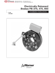
AT Brakes
P-218
819-0334
Installation Instructions
Contents
Introduction . . . . . . . . . . . . . . . . . . . . . . . . . . . 2
Brake Installation . . . . . . . . . . . . . . . . . . . . . . . 3
AT Brake Troubleshooting Guide . . . . . . . . . . . 5
Warranty . . . . . . . . . . . . . . . . . . . . . . Back Page
Failure to follow these
instructions may result in product damage, equipment damage, and serious or
fatal injury to personnel.
The Warner Electric AT brake you have purchased has been designed to provide long and
trouble-free service. It is a rugged and durable
unit which is rebuildable with both friction face
replacement and complete brake rebuild kits
offered in this service manual. The friction face
replacement kit renews the friction surfaces,
while the complete brake rebuild kit includes
new bearings, Autogap™ components and
hardware in addition to the friction faces.
For friction material replacement refer to manual
819-0341.
For complete rebuild refer to manual 819-0325.
This service manual includes instructions
required for installation, troubleshooting information.
All installation and repair involving AT brakes
must be carried out in accordance with the procedures specified in the service manual. All stated or implied manufacturer warranties are voided if this product is not installed and serviced in
accordance with these instructions.
2
Warner Electric • 800-825-9050
819-0334
Brake Installation
1. Remove your AT brake from its shipping carton and inspect it thoroughly to ensure that it
has arrived in good condition.
4. Slide the brake onto its shaft over its key.
If the brake is to be operated in a vertical
position, it must be mounted with the
armature fins up.
An accessory kit included with your brake
contains a coil wire retainer. In addition, you
may have ordered the optional brake torque
arm.
2. If used, install the Warner Electric conduit
box or conduit box/CBC-100 control combination in accordance with instructions furnished with the conduit box.
3. The Warner Electric patented Autogap automatically adjusts the proper operating gap
between the armature and friction face for
the life of these components.The proper gap
is approximately .050". If the armature and
friction face have moved during shipment, reset the Autogap by pushing the armature
against the friction material face. Release.
The armature will spring back about .050"
and the proper gap is set.
Warner Electric • 800-825-9050
5. Install the optional Warner Electric torque arm
or the customer furnished pin. The arm must
be strong enough to withstand the brake’s
full torque capacity, and should be affixed to
the machine frame, and to the brake tangent
to its circumference in the notched attachment point on the back plate. It must also be
flexible enough to compensate normal shaft
and bearing runout without causing binding
or side loading to the brake.
819-0334
3
6. Tighten the set screws located in the hub to
the appropriate torque for your size unit:
Size
Torque
25
80 in.-lbs.
55
160 in.-lbs.
115
275 in.-lbs.
10. Your AT brake may not achieve its full
torque until after a short “break-in” period.
To break in the brake, cycle it on and off
under full load at operating speed a minimum of ten times in quick succession.
Your AT brake is now ready to run.
Note: Depending on application break in period may be longer due to load and RPM, and
require more cycles.
Wear Indication
7. Attach the wires to the DC power source,
using wire nuts or other approved connecting
devices. Either wire can be connected to the
+ or - of the voltage source. If a Warner
Electric CBC-100 or other Warner Electric
control is used as the power source, follow
the connection diagram supplied with the
control. Assure that the voltage rating of the
brake is the same as the output rating of the
power source.
Your AT brake should be visually inspected on a
periodic basis to determine if the wearing surfaces warrant replacement. The friction face and
armature should be replaced when the armature
reaches the wear indicator on the magnet shell.
If replacement is not made at this time, further
use will wear into the screw heads, making
removal and replacement of the friction facing
difficult. The drawing below illustrates the area
to be inspected.
When the friction surfaces are worn to this
point, replace with the appropriate friction face
replacement kit. All of the components needed
to refurbish the wearing surfaces of your brake
are provided in the replacement kit.
Wear Indicator
Friction Face
Armature
8. Your AT brake is now ready for its static test.
Apply DC voltage to the coil through the
brake control. The armature should pull
against the friction material face with an audible click.
9. Run the brake under its operating load.
4
Warner Electric • 800-825-9050
819-0334
AT Brake Troubleshooting Guide
If performance problems are present after carefully following the instructions in this manual, use the
following check list.
Symptom
Check
Problem
Clutch Rotor will not move or
engage when power is applied
to the coil
Possible Causes
• Coil Resistance
Coil may be open. See Chart 1.
• Power Supply
Assure proper DC voltage is being delivered to the brake
• Airgap
If greater than .050" around entire periphery, reset Autogap.
• Autogap
Assure that brake armature is free to move on hub spline and releases approximately .050" when pressure is removed.
Vibration
• Runout
Assure that shaft on which the clutch is mounted doesn't have excessive runout.
• Shaft Engagement
Assure adequate shaft length and diameter engagement in the hub.
Excessive Start or Stop Times
• Power Supply
Assure proper DC voltage is being delivered to the brake.
• Adequate Burnishing
Unit must be run and cycled a few times to achieve full rated torque.
• Friction Surfaces
Replacement may be required.
• Friction Surfaces
Installation of replacement friction material or armature segments may be
incorrect and not allow full contact.
Clutch/Brake
Size
Coil
Voltage
Approx. Coil
Resistance (Ohms)
25
6
1.4
25
24
20.6
25
90
290
55
6
1.2
55
24
19.6
55
90
230
115
6
1.0
115
24
16.5
115
90
182
Chart 1
Warner Electric • 800-825-9050
819-0334
5
Warranty
Warner Electric LLC warrants that it will repair or replace (whichever it deems advisable) any
product manufactured and sold by it which proves to be defective in material or workmanship
within a period of one (1) year from the date of original purchase for consumer, commercial or
industrial use.
This warranty extends only to the original purchaser and is not transferable or assignable without
Warner Electric LLC’s prior consent.
Warranty service can be obtained in the U.S.A. by returning any defective product, transportation
charges prepaid, to the appropriate Warner Electric LLC factory. Additional warranty information
may be obtained by writing the Customer Satisfaction Department, Warner Electric LLC, 449
Gardner Street, South Beloit, Illinois 61080, or by calling 815-389-3771.
A purchase receipt or other proof of original purchase will be required before warranty service is
rendered. If found defective under the terms of this warranty, repair or replacement will be made,
without charge, together with a refund for transportation costs. If found not to be defective, you
will be notified and, with your consent, the item will be repaired or replaced and returned to you
at your expense.
This warranty covers normal use and does not cover damage or defect which results from
alteration, accident, neglect, or improper installation, operation, or maintenance.
Some states do not allow limitation on how long an implied warranty lasts, so the above limitation
may not apply to you.
Warner Electric LLC’s obligation under this warranty is limited to the repair or replacement of the
defective product and in no event shall Warner Electric LLC be liable for consequential, indirect,
or incidental damages of any kind incurred by reason of the manufacture, sale or use of any
defective product. Warner Electric LLC neither assumes nor authorizes any other person to give
any other warranty or to assume any other obligation or liability on its behalf.
WITH RESPECT TO CONSUMER USE OF THE PRODUCT, ANY IMPLIED WARRANTIES WHICH
THE CONSUMER MAY HAVE ARE LIMITED IN DURATION TO ONE YEAR FROM THE DATE OF
ORIGINAL CONSUMER PURCHASE. WITH RESPECT TO COMMERCIAL AND INDUSTRIAL
USES OF THE PRODUCT, THE FOREGOING WARRANTY IS IN LIEU OF AND EXCLUDES ALL
OTHER WARRANTIES, WHETHER EXPRESSED OR IMPLIED BY OPERATION OF LAW OR
OTHERWISE, INCLUDING, BUT NOT LIMITED TO, ANY IMPLIED WARRANTIES OF
MERCHANTABILITY OR FITNESS.
Some states do not allow the exclusion or limitation of incidental or consequential damages, so
the above limitation or exclusion may not apply to you. This warranty gives you specific legal
rights and you may also have other rights which vary from state to state.
Changes in Dimensions and Specifications
All dimensions and specifications shown in Warner Electric catalogs are subject to change without
notice. Weights do not include weight of boxing for shipment. Certified prints will be furnished
without charge on request to Warner Electric.
Warner Electric LLC
31 Industrial Park Road • New Hartford, CT 06057
815-389-3771 • Fax: 815-389-2582
www.warnerelectric.com
P-218 819-0334 6/05
Printed in USA