1
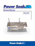
Service Manual
Revised 5/7/04
1
Table of Contents
Preventive Maintenance
Page 2-3
Routine Preventive Maintenance
Daily
Monthly
Notes
Troubleshooting
Component Operation & Checks
Pages 4-6
Pages 7-10
Parts List
Pages 11-15
Electrical Schematic
Pages 16-19
Pump and Motor Assembly
Pages 21-25
Appendix
Notes
2
Page 26
Explanation of Warning Messages
Be sure to read, understand and follow all DANGER, WARNING, and CAUTION
messages located in this guide and on the equipment.
Danger
Personal Injury and Property Damage hazard.
May result in serious injury or death.
May cause extensive equipment damage
Warning
Property Damage Hazard.
May result in property or equipment damage.
Personal Injury Hazard
Hazard from sharp objects.
May result in serious injury or death.
Chemical Hazard
May result in serious injury or death. Instructions, labels and
Material Safety Data Sheets (MSDSs) should be supplied with all
detergents and sanitizing chemicals. The manufacturers, importers
and distributors of your cleaning chemicals are responsible for
providing this information.
3
Preventive Maintenance
Your system requires minimal, routine preventive maintenance. As such, the following
should be done on a routine basis to ensure that your system remains reliable:
Daily
Clean the liquid level sensors. These sensors are located on the side walls of the wash and
sanitizer tanks. They are the white plastic discs with metal centers. Clean the sensor faces
thoroughly. If cleaned regularly, a washcloth and soapy water are all that is required.
If the liquid level sensors are not cleaned regularly, the machine
may fail to operate; or it may be possible to run it without water,
which may cause serious damage to the unit.
Monthly
IMPORTANT: Turn off the power to the unit at the main breaker
prior to performing the following task!
After shutting off the power at the system’s dedicated breaker, clean the pump motor fan
shroud with a stiff bristle brush and a vacuum. If a brush and vacuum are unavailable, clean
the shroud with a damp, soapy rag. The motor shroud is the "vented" cover located at the end
of the motor (closest to the control panel). This will prevent grease and dust from
accumulating in the cover's openings, which can obstruct the airflow that cools the motor.
De-lime the wash sink. Simply add a de-liming agent to a sink of warm, fresh water and run
the system overnight.
Ask your chemical sales representative to recommend a specific de-liming agent.
There are no other preventive maintenance procedures that you will need to perform on your
Power Soak system. You need not be concerned about greasing the motor bearings, as they
are permanently sealed. If you have any questions regarding the preventive maintenance
procedures, please contact the factory at 800-444-9624.
4
Troubleshooting
Hazard to untrained or unauthorized personnel.
The following procedures are provided for use only by an
authorized service agency. No facility owner, manager, employee
or other unauthorized person should attempt to perform any of these
procedures. To obtain the name of a recommended service agent in
your area, please call the Metcraft, Inc. Power Soak Service
Department at 800-444-9624.
When performing troubleshooting procedures, the authorized
service agency will need to open the Power Soak system's main
electrical enclosure.
Properly close the control panel before reconnecting the circuits.
5
Troubleshooting
PS-200
Pump leaks
Look For
Correction
1 Defective ADAPTER O-RING
replace
2 Defective PUMP SEAL
Replace
Intermittent running
See “Pump does not work” below
Pump does not work
Look For
1 Slow Flashing Green Light
2 Solid Blue Light
Correction
Clean Liquid Level Sensors
Fill sink with water to proper level
Tighten the External Wiring Harness on back of Control Panel
Clean Liquid Level Sensors
Drain sink and refill with water to proper level
3 Error LED on UPM
Record the pattern – See “Error Codes”
4 Red, Green, Blue lights blinking together
Low power to UPM – See “No Power”
5 No indicator lights at all
Water too hot – reduce temperature to 115°F with ice or cold water
See “No Power”
Pump works – Heater does not work
Look For
1 Water temperature < 110°F
Correction
2 Water temperature between 110°F and 120°F
Check Heater and replace as necessary
Check Triac(s) and replace as necessary
Normal operating temperature
3 Water temperature > 120°F
Water too hot – reduce temperature to 115°F with ice or cold water
Water too hot or not hot enough
Look For
1 Water temperature < 110°F
2 Water temperature between 110°F and 120°F
3 Water temperature > 120°F
6
Correction
Check Heater and replace as necessary
Check Triac(s) and replace as necessary
Normal operating temperature
Check Thermistor and replace as necessary
Too much soap can cause excessive heat buildup
Troubleshooting
PS-200
No Power
Look For
Correction
1 Incoming voltage between L1 and L2 (L1-L2)
(Also L1-L3, L2-L3 if 3 phase)
2 Less than 10 volts to UPM
(leave UPM plugged in during check)
Check Heater and replace as necessary
Water too hot, above 135°F – empty sink and refill with 115°F water
Tighten the External Wiring Harness on back of Control Panel
Check transformer and replace as necessary
Check thermal cutoff for heater and replace as necessary
Check thermal cutoff for motor and replace as necessary
Error Codes
~ Represents a “long” flash
* Represents a “short” flash
Look For
1
2
3
7
~~~*
~~~**
~~~***
Correction
This indicates a Water Level problem.
Turn off breaker to sink. Drain sink, clean sensors, refill sink. Turn on breaker to sink.
This indicates a Temperature Sensor problem.
Tighten the External Wiring Harness on back of Control Panel.
Check and replace Thermistor as necessary.
This indicates an Over-Current problem.
Check and Replace motor and/or heater as necessary.
Check and Replace UPM or CT as necessary.
Component Operation and Checks
The following checks should only be performed by qualified
technicians using extreme caution.
Electrical hazard to untrained personnel may result in electrical
shock, burns, or death.
Liquid Level Sensors
There are two Liquid Level Sensors (LLS) in the wash sink, and two more in the sanitize sink
(if equipped with a sanitize sink). To check operation, first unplug the white connector from
the UPM. Measure the resistance between the face of the LLS and the appropriate pin of the
white connector. You should read less than one ohm. Refer to the chart below for the
appropriate pins.
Description
UPM pin number
Wire color
Wash Sink Low LLS
Wash Sink High LLS
Sanitize Sink Low LLS
Sanitize Sink High LLS
Pin 19
Pin 20
Pin 21
Pin 22
White with Orange stripe
White with Green stripe
White with Yellow stripe
White with Blue stripe
If you read higher than that, you may have a dirty sensor, a broken wire, or a loose
connection. The loose connection may be at the sensor on your wiring harness, or the
external wiring harness may not be tight at the back of the Control Panel.
Thermistor
The Thermistor is a temperature sensor. The UPM measures the resistance through the
Thermistor, and associates that resistance to a temperature. To check operation, first unplug
the white connector from the UPM. Next, measure the resistance across the Thermistor.
This reading can be attained at the white UPM connector (reference “UPM” for pin layout),
between pin 8 and pin 9. If your reading varies significantly from the TemperatureResistance chart in Appendix A, the Thermistor may be defective. The UPM will signal an
error if it reads a resistance greater than 430 k and less than 15 k . The Thermistor is
located close to the Heater, inside the Sensor Pad. When replacing a Thermistor, it is helpful
to use a glue dot to hold it in place while reattaching the Sensor Pad to the sink. Also, it is
imperative to put heat sink compound on the side of the Thermistor that will be against the
sink, and the Heater Thermodisc as well, to help ensure good heat transfer.
8
Component Operation and Checks
Heater Thermodisc (Hi-Limit or Cutoff Switch)
The Heater Thermodisc is a protection device. If the temperature at the Thermodisc reaches
135°F, the disc opens, cutting off power to the UPM. To check operation, first shut off the
circuit breaker to the sink. Next, unplug the connectors P9 and J10 from J9 and P10 for the
Motor Thermodisc (reference schematic or “Motor Thermodisc” for location and
description). Measure the resistance between J10 and the center-tap of the transformer
(reference schematic or “Transformer” for location). Device should read less than one ohm
when closed. If you read more than one ohm, the Thermodisc may be defective. Next, check
for a short to ground. If you find a short to ground from either side of the Thermodisc, the
Thermodisc is either defective, or you may have water in the sensor pad. This condition will
keep the UPM from operating correctly. The Thermodisc is located close to the Heater,
inside the Sensor Pad. When replacing a Thermodisc it is helpful to use a glue dot to hold it
in place while reattaching the Sensor Pad to the sink. Also, it is imperative to put heat sink
compound on the side of the Thermodisc that will be against the sink, and the Thermistor as
well, to help ensure good heat transfer.
Motor Thermodisc (Hi-Limit or Cutoff Switch)
The Motor Thermodisc is a protection device. If the temperature at the Thermodisc reaches
180°F, the disc opens, cutting off power to the UPM. To check operation, first shut off the
circuit breaker to the sink. Next, unplug the connectors P9 and J10 from J9 and P10 for the
Motor Thermodisc (reference schematic for location and description). These connectors plug
the two Thermodisc wires (black) to two yellow wires coming out of the internal wiring
harness of the Control Panel. Measure the resistance between J9 and P10 (reference
schematic, these are the black Thermodisc wires). The device should read less than one ohm
when closed. If you read more than one ohm, the Thermodisc may be defective. Next, check
for a short to ground. If you find a short to ground from either side of the Thermodisc, the
Thermodisc is either defective, or you may have water on the Thermodisc. This condition
will keep the UPM from operating correctly. On some of our motors, the Thermodisc is built
in to the motor, which is not replaceable. On others, it is located in the wiring box of the
Motor, which is replaceable. When replacing, it is imperative to put heat sink compound on
the side of the Thermodisc that will be against the motor to help ensure good heat transfer.
9
Component Operation and Checks
Transformer
The Transformer reduces the incoming power supply voltage to 24 volts, with a 12-volt
center-tap. The transformer has acceptable inputs of 120, 240, and 277 volts. It should
already be wired to the specifications of Control Panel (refer to schematic). To test the
Transformer, first verify the input voltage. This can be done between the L2 terminal and the
down-stream/transformer side of the fuse. The fuse holder can be found on the end of the
terminal strip. Next, verify the output voltage of the Transformer. You should get 24 volts
across it, and 12 volts between the center-tap and each of the other outputs. These voltages
can be verified at the three wire nuts on the internal wiring harness near the Transformer.
Note the wire colors on the schematic for each wire nut.
Triac (Thyristor or Solid-State Relay)
The Triac is a three terminal semiconductor for controlling current in either direction. Our
use for the Triac is similar to a contactor. When a gate voltage is applied from the UPM
(similar to coil voltage on a mechanical Contactor Relay), the Triac conducts (closes)
through the power terminals. On a single phase Control Panel, there are two Triacs, one for
the Heater, the other for the Motor. Terminals 2 and 3 on each Triac are supplied with
incoming voltage. On the top of these Triacs, they are labeled M1 (motor leg 1) and H1
(heater leg 1). On a three phase Control Panel there are four Triacs, two for the Heater, and
two for the Motor. Two are labeled identically to a single phase Panel. The two others are
labeled M3 (motor leg 3) and H3 (heater leg 3). Terminals 2 and 3 on each Triac are
supplied with incoming voltage. To test the Triac, first verify the input voltage to the Triac.
An LED on the Triac board signals whether gate voltage has been applied by the UPM. If
this light is on, the Triac should be closed, and terminal 1 of the Triac should be supplying
power to the respective device. If the LED is off, there should be virtually no current on the
output side of the Triac.
10
Component Operation and Checks
Contactor
If there is 20v-28v across the coil and the contactor does not pull in, the contactor is
defective. If there is input voltage across terminals L1 and L2 (also L1-L3 and L2-L3, if
three phase) and the contactor is pulled in, but no voltage across terminals T1 and T2 (also
T1-T3 and T2-T3, if three phase), the contactor is defective.
Heater Element
The heater in a PowerSoak sink is rated at 7000 watts. To check operation of the heat
element, first turn the power off at the breaker. Disconnect the H2 wire from terminal H2
and the H1 wire from the triac H1 (and H3 wire from H3 triac, if 3 phase) from the Control
Panel. Check each heater lead to ground for a short. They all should be open to ground.
Check resistance between each of the combinations of the chart below.
Connection
H1-H2
H1-H2
H2-H3
H1-H3
H1-H2
H1-H2
H2-H3
H1-H3
Heater rated voltage
208-230
208-230
208-230
208-230
460
460
460
460
phase
1
3
3
3
1
3
3
3
Resistance (ohms)
7.56
15.12
15.12
15.12
32.91
65.83
65.83
65.83
The heater should be within about 10% of the value in the chart.
If the reading varies significantly from the chart above, the heater may be defective, or there
may be a broken wire or loose connection.
Electrically, the Heater is three separate elements, each of 2333 watts. When replacing, note
how the existing Heater is wired, and refer to the schematic when wiring the new Heater.
11
Parts List
Motor – Impeller – Pump Assembly
60 Hz - self-draining
HP
Side
Phase
Volt
Wet End
Motor
Impeller
1.5
1.5
1.5
1.5
1.5
1.5
1.5
1.5
2.0
2.0
2.0
2.0
2.0
2.0
2.0
2.0
3.0
3.0
5.0
5.0
5.0
5.0
LH
RH
LH
RH
LH
RH
LH
RH
LH
RH
LH
RH
LH
RH
LH
RH
LH/RH
LH/RH
LH
RH
LH
RH
1
1
1
1
3
3
3
3
1
1
1
1
3
3
3
3
3
3
3
3
3
3
208
208
230
230
208
208
230/460
230/460
208
208
230
230
208
208
230/460
230/460
208
230/460
208
208
230/460
230/460
29600
29601
29602
29603
29604
29605
29606
29607
29608
29609
29610
29611
29612
29613
29614
29615
29616
29617
29618
29619
29620
29621
29506
29506
29500
29500
29508
29508
29502
29502
29507
29507
29501
29501
29509
29509
29503
29503
29510
29504
29511
29511
29505
29505
27590
27591
27590
27591
27590
27591
27590
27591
27592
27593
27592
27593
27592
27593
27592
27593
27594
27594
27596
27597
27596
27597
60 Hz - non self-draining
12
HP
side
Phase
Volt
Wet End
Motor
Impeller
1.5
2.0
2.0
3.0
LH
LH
LH
LH
1
1
3
3
208/230
208/230
230/460
230/460
27548
27554
27558
27566
see above
see above
see above
see above
27590
27592
27592
27594
Parts List
Motor – Impeller – Pump Assembly
50 Hz - European
HP
side
Phase
Volt
Wet End
Motor
Impeller
1.5
1.5
1.5
1.5
2.0
2.0
3.0
3.0
5.0
5.0
LH
RH
LH
RH
LH/RH
LH/RH
LH
RH
LH
RH
1
1
3
3
1
3
3
3
3
3
220
220
380
380
220
380
380
380
380
380
29622
29623
29624
29625
29626
29627
29628
29629
29630
29631
29512
29512
29514
29514
29513
29515
29516
29516
29517
29517
27592
27593
27592
27593
27594
27594
27488
27489
?
?
Pump Parts Common to all
13
Part #
Description
28920
27886
27047
27132
27480
27475
27476
27477
27478
27479
27481
27483
28262
Seal Kit
Thermodisc - motor - thermal cutoff
Intake gasket
Discharge gasket
Mechanical Seal
"O" ring - sleeve
"O" ring - seal plate
Key
Impeller Bolt
Fiber Washer
Sleeve
Cap Screw - seal plate
Dowel Pin
Parts List
Heater
Part #
Description
27743
27744
27839
29243
27930
29244
27939
27934
27702
27934
29654
27934
18797
27926
28454
27322
28928
28881
Element - 230 volt - rev. A - ribbon - rear mount
Element - 460 volt - rev. A - ribbon - rear mount
Gasket for Chromolox heater
Element - 208 volt -rev. B - wire - bottom mount - not available yet
Element - 230 volt -rev. B - wire - bottom mount
Element - 380 volt -rev. B - wire - bottom mount - not available yet
Element - 480 volt -rev. B - wire - bottom mount
Gasket for Accutherm heater
Cover - rev. A - front mount - 17"
Cover - rev. B - angle mount - 14"
Cover - rev. C - after 02/05/04 - 12"
Bolt - heater cover
Terminal strip - heater
Thermistor - temperature sensor
Thermodisc - heater - thermal cutoff
Sensor pad
Heatsink compound
Glue dot
14
Parts List
Control Panel
Part #
27901
27902
27903
27171
27172
27920
27923
27924
27925
27928
28923
27927
27200
27922
Description
Control Panel 220 volt single phase
Control Panel 220 volt three phase
Control Panel 480 volt three phase
Contactor
Transformer - 24 volt
UPM - Programming Module
Terminal Block
Grounding Block
Din Rail - mount for terminal blocks
Triac - solid state relay
Fuse Block
Heatsink
Overlay - start/stop membrane
Wiring Harness - internal to control panel
Miscellaneous
Part #
23987
23988
27847
27848
28065
28066
28669
27854
27854
28553
27855
15
Description
Liquid Level Sensor
Gasket - Liquid Level sensor
Wiring Harness - Wash
Wiring Harness - Sanitize
Wiring Harness Extension - 3 ft
Wiring Harness Extension - 6 ft
Utensil Basket
Chemical Injector
Connector - chemical injector
Cap - chemical injector
Gasket – Chemical Injector
Parts List
Optional Chemical Dispenser
Dual Pump Chemical Dispenser
Part #
28900
28370
29233
29230
29231
29232
29235
29234
28067
29236
29237
29238
29239
29240
29241
29242
28703
28704
103-014
27858
28557
28901
29145
28555
16
Description
Chemical Dispenser - Dual Pump - Generic
Chemical Dispenser - Dual Pump - Kay Chemical
Timer - solidstate
Button Guard - metal
Switch - MOM - N/O - metal
Rectifier - bridge
Lock & Key
Motor - 24 volt - 120 rpm
Wiring Harness - soap dispenser
Hook & Loop
Screw - #8-32 x 1/2" flat phillips s/s
Spring Cone
Screw - #10-24 x 1-3/4" pan phillips s/s
Pump - 2 cc power wash
Tape - double sided foam
Key
Screw - #6-32 s/s
Nut - hex #6-32 s/s
Nut Sert - #10-24 tsn
Gasket - soap dispenser - PS-200
Overlay - soap dispenser - Kay Chemical
Overlay - soap dispenser - generic
Terminal Fork 22-18 #8 Insulated
Decal - Overlay - Metcraft service
PowerSoak
Electrical Schematic
208-240 volt 60 Hz 1 phase
17
13910 Kessler Drive.
Grandview MO. 64030
®
Systems
METCRAFT INC./POWERSOAK® CLAIMS PROPRIETARY RIGHTS IN THE MATERIAL HEREIN DISCLOSED. IT IS SUPPLIED IN
CONFIDENCE, WITHOUT PREJUDICE TO ANY PATENT RIGHTS OF METCRAFT INC., AND MAY NOT BE REPRODUCED, SHARED
OR USED TO MANUFACTURE ANYTHING SHOWN THEREIN WITHOUT METCRAFT INC.'S WRITTEN PERMISSION.
ALL INFORMATION ALWAYS REMAINS THE SOLE PROPERTY OF METCRAFT INC.
Power Soak® is a registered trademark of Cantrell Ind., Inc.
Licensed by Cantrell Ind., Inc.
TITLE
Mark C
DATE
7/10/2002
DATE REV
1/14/2004
SIZE
A
ECR.
.
SCALE
NTS
#.
DWG
.
DO NOT SCALE DRAWING
27904
SHEET 1 OF 1
REV
F
PS-200
DRAWN BY
PS-200 WIRING DIAGRAM
208/240V 60Hz 1 PH
PowerSoak
Electrical Schematic
208-240 volt 60 Hz 3 phase
18
13910 Kessler Drive.
Grandview MO. 64030
®
Systems
METCRAFT INC./POWERSOAK® CLAIMS PROPRIETARY RIGHTS IN THE MATERIAL HEREIN DISCLOSED. IT IS SUPPLIED IN
CONFIDENCE, WITHOUT PREJUDICE TO ANY PATENT RIGHTS OF METCRAFT INC., AND MAY NOT BE REPRODUCED, SHARED
OR USED TO MANUFACTURE ANYTHING SHOWN THEREIN WITHOUT METCRAFT INC.'S WRITTEN PERMISSION.
ALL INFORMATION ALWAYS REMAINS THE SOLE PROPERTY OF METCRAFT INC.
Power Soak® is a registered trademark of Cantrell Ind., Inc.
Licensed by Cantrell Ind., Inc.
DRAWN BY
Mark C
DATE
7/10/2002
DATE REV
1/14/2004
SIZE
A
PS-200 WIRING DIAGRAM
208-240V 60Hz 3 PH
ECR.
.
SCALE
NTS
#.
DWG
.
DO NOT SCALE DRAWING
27905
SHEET 1 OF 1
REV
G
PS-200
TITLE
PowerSoak
Electrical Schematic
460 volt 60 Hz 3 phase
19
13910 Kessler Drive.
Grandview MO. 64030
®
Systems
METCRAFT INC./POWERSOAK® CLAIMS PROPRIETARY RIGHTS IN THE MATERIAL HEREIN DISCLOSED. IT IS SUPPLIED IN
CONFIDENCE, WITHOUT PREJUDICE TO ANY PATENT RIGHTS OF METCRAFT INC., AND MAY NOT BE REPRODUCED, SHARED
OR USED TO MANUFACTURE ANYTHING SHOWN THEREIN WITHOUT METCRAFT INC.'S WRITTEN PERMISSION.
ALL INFORMATION ALWAYS REMAINS THE SOLE PROPERTY OF METCRAFT INC.
Power Soak® is a registered trademark of Cantrell Ind., Inc.
Licensed by Cantrell Ind., Inc.
DRAWN BY
Mark C
DATE
7/10/2002
DATE REV
1/14/2004
SIZE
A
PS-200 WIRING DIAGRAM
460V 60Hz 3 PH
ECR.
.
SCALE
NTS
#.
DWG
.
DO NOT SCALE DRAWING
27906
SHEET 1 OF 1
REV
G
PS-200
TITLE
Electrical Schematic
400 volt 50 Hz 3 phase
20
European
13910 Kessler Drive.
Grandview MO. 64030
PowerSoak
®
Systems
METCRAFT INC./POWERSOAK® CLAIMS PROPRIETARY RIGHTS IN THE MATERIAL HEREIN DISCLOSED. IT IS SUPPLIED IN
CONFIDENCE, WITHOUT PREJUDICE TO ANY PATENT RIGHTS OF METCRAFT INC., AND MAY NOT BE REPRODUCED, SHARED
OR USED TO MANUFACTURE ANYTHING SHOWN THEREIN WITHOUT METCRAFT INC.'S WRITTEN PERMISSION.
ALL INFORMATION ALWAYS REMAINS THE SOLE PROPERTY OF METCRAFT INC.
Power Soak® is a registered trademark of Cantrell Ind., Inc.
Licensed by Cantrell Ind., Inc.
DRAWN BY
Mark C
DATE
7/10/2002
DATE REV
1/14/2004
SIZE
A
PS-200 WIRING DIAGRAM
400V 50Hz 3 PH
ECR.
.
SCALE
NTS
#.
DWG
.
DO NOT SCALE DRAWING
27890
SHEET 1 OF 1
REV
F
PS-200
TITLE
Electrical Schematic
230 volt 50 Hz 3 phase
21
European
13910 Kessler Drive.
Grandview MO. 64030
PowerSoak
®
Systems
TITLE
DRAWN BY
DATE
DATE REV
Mark C
7/10/2002
1/14/2004
SIZE
A
PS-200 WIRING DIAGRAM
230V 50Hz 1 PH
ECR.
.
SCALE
NTS
#.
DWG
.
DO NOT SCALE DRAWING
27894
SHEET 1 OF 1
REV
F
PS-200
METCRAFT INC./POWERSOAK® CLAIMS PROPRIETARY RIGHTS IN THE MATERIAL HEREIN DISCLOSED. IT IS SUPPLIED IN
CONFIDENCE, WITHOUT PREJUDICE TO ANY PATENT RIGHTS OF METCRAFT INC., AND MAY NOT BE REPRODUCED, SHARED
OR USED TO MANUFACTURE ANYTHING SHOWN THEREIN WITHOUT METCRAFT INC.'S WRITTEN PERMISSION.
ALL INFORMATION ALWAYS REMAINS THE SOLE PROPERTY OF METCRAFT INC.
Power Soak® is a registered trademark of Cantrell Ind., Inc.
Licensed by Cantrell Ind., Inc.
Motor and Pump Assembly
Exploded view
1
3
9
6
5
4
7
10
8
2
14
15
16
11
Item
1
2
3
4
5
6
7
8
*
*
*
12
13
Description
Casing
Cotter pin – part of casing
Stud – part of casing
Impeller screw - 9/16” hex
Impeller washer
Impeller
Impeller key
Sleeve O-ring
Item
9
10
11
12
13
14
15
16
*
*
* Indicates parts included in the seal kit
22
Description
Shaft Sleeve
Mechanical Seal
Adapter O-ring
Motor bolt – 5/16” allen
Adapter plate
Washer
Casing Nut – 9/16” hex
Motor
Motor and Pump Assembly
DISASSEMBLY PROCEDURE:
1. Remove (3) nuts from the back of the adaptor plate. Slide the pump end out from
the volute.
2. Holding the impeller to keep it from turning, loose the washer head cap screw,
remove the screw and gasket.
3. Slide the impeller off of the shaft and remove the key.
4. Remove the seal/sleeve as a unit by pulling it off of the shaft. Some corrosion
may prohibit movement and a lubricant may be used to penetrate between the
sleeve and motor shaft. With the impeller and key removed, the shaft sleeve and
the mechanical seal assembly can be removed.
5. Remove O-ring from the shaft sleeve.
6. With the shaft sleeve removed, the seal rotating assembly can be pulled off of the
shaft sleeve.
7. Mark the adaptor plate and motor to insure proper re-assembly. Remove (4)
screws from the adaptor plate. Take the adaptor plate off the motor.
8. Remove o-ring from adaptor plate.
9. With the adaptor plate removed, the seal seat can be removed using a screwdriver
or by using your fingers.
INSPECTION OF THE COMPONENTS:
With pump end disassembled, clean all parts and check for worn and damaged areas.
Worn or damaged metal parts should be replaced. The mechanical seal, gasket, oring, O-ring and washer head cap screw are replacement parts that are provided in the
kit. All old parts must be discarded and are not to be reused.
ASSEMBLY PROCEDURE:
1. Push the mechanical seal seat squarely into the seal bore of the adaptor plate by
using fingers. A little lube can be used on the seal bore of the adaptor plate. Make
sure that ceramic side up and it is fully seated.
2. Install the adaptor plate and tighten (4) screws, which hold it to the motor face.
Make sure the marks made in step 7 above line up.
3. Install o-ring into the groove of the adaptor plate.
23
4. Coat the shaft sleeve lightly with lube. Install the mechanical seal on the shaft
sleeve using your hand to push against the seal face. Make sure rubber seal
bellows are seated against sleeve shoulder and carbon seal face is not scratched or
chipped.
5. Slide the shaft sleeve onto the motor shaft and install the O-ring on the groove of
the sleeve. Using lube or grease on the O-ring will help hold the ring in place
temporarily until the impeller is secured.
6. Install the key on the motor shaft and place the impeller on the motor shaft
engaging the key.
7. Put the gasket on the washer head cap screw.
8. Install the impeller cap screw by holding the impeller, push the impeller back
against the sleeve and the other hand tighten the screw to 23-ft.lbs. of torque. (Do
not over tighten as this could cause the gasket to squeeze out, become deformed
and not seal properly.
9. Slide the pump end on the (3) studs of the volute. The motor junction box should
be at the bottom.
10. Install (3) nuts on the studs and tighten to 23-ft.lbs.
24
Appendix A
95
10
0
10
5
11
0
11
5
12
0
12
5
13
0
13
5
14
0
14
5
85
90
75
80
150
140
130
120
110
100
90
80
70
60
50
40
30
20
65
70
Resistance (K ohms)
Thermistor Resistance-Temperature Chart
Temperature (degrees Fahrenheit)
25
Notes
______________________________________________
______________________________________________
______________________________________________
______________________________________________
______________________________________________
______________________________________________
______________________________________________
______________________________________________
______________________________________________
______________________________________________
______________________________________________
______________________________________________
______________________________________________
______________________________________________
______________________________________________
______________________________________________
______________________________________________
______________________________________________
______________________________________________
______________________________________________
______________________________________________
______________________________________________
______________________________________________
______________________________________________
______________________________________________
______________________________________________
26
Notes
______________________________________________
______________________________________________
______________________________________________
______________________________________________
______________________________________________
______________________________________________
______________________________________________
______________________________________________
______________________________________________
______________________________________________
______________________________________________
______________________________________________
______________________________________________
______________________________________________
______________________________________________
______________________________________________
______________________________________________
______________________________________________
______________________________________________
______________________________________________
______________________________________________
______________________________________________
______________________________________________
______________________________________________
______________________________________________
______________________________________________
27
Power Soak is a registered trademark of Cantrell Industries, Inc.
The Power Soak design and concept is fully patented.
13910 Kessler Drive, Grandview, MO 64030
Phone: (816) 761-3250 Fax: (816) 761-0544
(800) 444-9624
www.powersoak.com
28