1
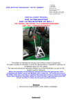
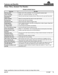
USER MANUAL
VM6000 SPRING TINE
CULTIVATOR
VM 6000 SPRING TINE CULTIVATOR
Contents
Page
1.
TECHNICAL DATA
2
2.
2.1
2.2
2.3
2.4
2.5
SAFETY INSTRUCTIONS
General instructions
Hydraulics
Protection against oil and grease
Waste oil
Accidents
3
3
4
4
4
4
3.
3.1
3.2
3.3
3.4
3.4.1
3.4.2
3.5
PUTTING THE CULTIVATOR INTO SERVICE
Hitching the cultivator to a tractor
Operating principle of the cultivator’s hydraulic system
Operating principle of the front-board and side-block hydraulics
Balancing and bleeding the hydraulic circuits
Balancing and bleeding the depth adjustment cylinders
Balancing and bleeding the front-board cylinders
Adjusting the position of the cultivator
5
5
5
6
6
6
7
7
4.
4.1
4.2
4.3
4.4
USING THE CULTIVATOR
Intended use and operation of the cultivator
Adjusting the cultivation depth
Using the boards
Using the rear following harrow
8
8
8
10
10
5.
5.1
5.2
TRANSPORTING THE CULTIVATOR
Transport position
Driving, driving speeds and passengers
11
11
11
6.
6.1
6.2
6.2.1
6.2.2
6.2.3
6.3
6.4
MAINTAINING AND STORING THE CULTIVATOR
Preparations before the maintenance work
Maintenance work on the cultivator
Lubricating and greasing points
Tyre pressure
Tightness of the bolts
Storing the cultivator
Starting up the machine after storing
12
12
12
12
13
13
14
14
7.
RESPONSIBILITIES
15
8.
WARRANTY TERMS
16
EU DECLARATION OF CONFORMITY
17
1
1. TECHNICAL DATA
The structural and operational dimensions and weights of the cultivator are presented in
Technical Data.
Technical data:
Operating width
Transport width
Number of tines
Number of tine shafts
Distance between tines
Horsepower requirement
Tyres
Weight
600 cm
340 cm
79 pcs.
7
7.5 cm
100 h.p.
200/60-14.5
2500 kg
Standard equipment:
Front levelling board
with 45x10 tines, tine blade 70x10
Fully hydraulic depth adjustment
Side-block bogie
Optional equipment:
Rear following harrow
Rear following board
Front levelling board, wide
Extension pieces to 700 cm
Reserve wheel bracket
Light set
2
with Ø12 tines
with 45x10 tines, tine blade 70x10
with 80x10 tines, tine blade 150x8
2x50 cm
2. SAFETY INSTRUCTIONS
2.1 General instructions
The VM Spring Tine Cultivator is intended for normal agricultural use and may be operated
by any person with a general knowledge of using agricultural machinery.
Before starting to use the cultivator, familiarize yourself with the machine, its operation and
the Instruction Manual. The cultivator must not be operated until you have familiarized
yourself with its operating and safety instructions and ensured that you completely
understand them.
Follow all warning and operational instructions affixed to the cultivator. These will help you
avoid accidents during the work.
Beware of getting squashed between moving parts of the machine while connecting the
cultivator to the tractor or when lifting or lowering it.
It is prohibited to stay near the cultivator, and in particular its side-blocks, while the
cultivator is connected to the tractor.
During operation, make sure no one is near the operating area.
Staying on top of the machine during road transportation or cultivation is strictly prohibited.
Before starting the work, make sure that both side-blocks have lowered to their extreme
positions.
Never use the cultivator if it is broken as a broken structure can easily collapse and cause
a risk of injury.
Raising or lowering the side-blocks of the cultivator is only allowed when the machine is
standing in position.
While driving the machine on public roads, follow all regulations of the Road Traffic Act
and, before setting out, make sure that all items of equipment required such as reflectors,
warning triangles and lights (optional), are properly in place and operational.
Do not allow anyone to use the cultivator without familiarizing themselves with its safety
and operating instructions and ensuring that these instructions have been correctly
understood.
Before commencing any maintenance, cleaning, lubrication, installation or adjustment
work, always make sure that the power take-off and the hydraulics have been switched off
and that the engine has been stopped. Remove the ignition key to prevent the tractor or
the implement from setting out inadvertently.
3
During maintenance work, the side-blocks must be in their lowest position and the
machine must be firmly supported on an even surface.
2.2 Hydraulics
When connecting or operating the harrow’s hydraulic system, always follow the safety
instructions written on the system.
1. After ending the operation, the hydraulic system always remains under high pressure.
A jet of oil may get injected into the skin and cause severe injuries. This risk of injury is
also present while searching for leaks.
2. Take care when handling all parts of the hydraulic system. During these operations you
run the risk of getting cut or squashed.
3. The hydraulic system must not be under pressure while the hoses are being connected
to the tractor.
4.
When replacing components or pipes of the hydraulic system, only use spare parts with
a sufficient pressure rating.
2.3 Protection against oil and grease
1. Always use appropriate protective clothing and gloves while handling oil or grease.
2. Avoid all skin contact with oil and grease. An injury to the skin may result.
3. Never use oil or lubrication grease for cleaning skin. These substances may contain
small metal particles that cause wounds which are worsened even more by the oil.
4. Follow all the operating instructions and safety instructions issued by the lubricant
manufacturers.
5. Synthetic oils are often corrosive and cause severe irritation.
2.4 Waste oil
Collect and dispose of the waste oil in accordance with national regulations.
2.5 Accidents
1. If oil gets spilled onto the soil, soak it up with peat (for example) to prevent it from
dispersing.
2. If injured by oil or lubricant, consult a doctor immediately.
4
3. PUTTING THE CULTIVATOR INTO SERVICE
Read the Operating Instructions carefully before putting the
cultivator into operation, and make sure that you understand
their contents correctly!
3.1 Hitching the cultivator to a tractor
Connect the drawbar of the cultivator to the tractor's hydraulically operated towing hook.
Connect the operating hoses side-block/front-board hydraulics to the double-acting outlet,
and move the tractor and the cultivator to as even a surface as possible for adjustment.
Before adjusting, make sure the double-acting functionality of the valve is activated and
that the floating position of the valve is not active. Keeping the floating position activated
may cause the working depth to vary during cultivation.
3.2 Operating principle of the cultivator’s hydraulic system
The bogie and levelling board cylinders are connected in series so that both the bogie
cylinders (3 pcs.) and the levelling board cylinders (3 pcs.) form circuits of their own.
Connection in series means that the oil flows from the rodside of the previous cylinder to
the pistonside of the next cylinder. Oil will then flow via the tractor’s valve to only the first
and the last cylinder (see Fig. 3.2.1).
Kuva 3.2.1
5
3.3 Operating principle of the front-board and side-block hydraulics
The front-board cylinders and the side-block cylinders are connected to a common valve
block. The position of the lever in the block determines whether the oil flows to the frontboard or the side-block cylinders (see Fig. 3.3.1). he position of the lever in the block is
determined by the level of the cultivator. In the work position, the valve allows the flow of
oil only to the front-board cylinders - in the transport position, the front-board circuit closes
and the oil flows to the side-block cylinders. The valve operates automatically once the
cultivator’s position is changed between the work position and the transport position.
Fig. 3.3.1
3.4 Balancing and bleeding the hydraulic circuits
The cylinders connected in series must be balanced when putting the cultivator into
operation for the first time or if the machine has not been used for a long period of time.
The depth adjustment cylinders must always be balanced before starting cultivation, and
probably also during the operation so as to achieve as smooth a cultivation result as
possible.
3.4.1 Balancing and bleeding the depth adjustment cylinders
The side-blocks must be brought to their lowest position for balancing the depth
adjustment cylinders. Lift the cultivator all the way up, and keep up the hydraulic pressure
by actuating the operating lever at low engine revolutions. The hydraulic oil will then
circulate through the entire circuit while simultaneously balancing and bleeding the entire
system.
6
3.4.2 Balancing and bleeding the front-board cylinders
The levelling board cylinders are balanced by retracting the piston rods of the cylinders
completely, and by keeping the pressure on by actuating the valve lever at low engine
revolutions. The hydraulic oil will then circulate through the entire circuit while
simultaneously balancing and bleeding the entire system. This ensures the synchronous
and smooth operation of the boards.
Note that just moving the cylinders to and fro is not sufficient for balancing the system, and
that therefore the balancing must be executed in the manner described above.
3.5 Adjusting the position of the cultivator
A smooth cultivation result requires that the frame of the cultivator be adjusted to a level
position.
During adjustment the tractor and the cultivator must be standing on an even surface. This
enables the frame to be brought to a level position by adjusting the toplink of the cultivator
(Fig. 3.5.1 Part 1). Shortening the toplink lowers the front end of the cultivator and
correspondingly, extending the link makes the front end rise. The toplink must be locked
using the locking piece in the link (Fig. 3.5.1 Part 2) as soon as the correct position is
found. Observe that the level position of the frame must be verified every time the
cultivator is hitched to a different tractor. It is a good idea to check the level position even
in the field before starting the operation, because the tractor and the cultivator might sink
into the field surface to slightly different levels.
Fig. 3.5.1
Part 2
Part 1
7
4. USING THE CULTIVATOR
4.1 Intended use and operation of the cultivator
The VM 6000 spring tine cultivator is used in combined tilling and seeding for levelling and
tilling the field surface in order to provide ideal growing conditions for the crops.
Before starting the tilling, lower the side-blocks to bring the cultivator to the transport
height. Make sure the side-blocks can be lowered freely and that no one is within the
danger zone. Remember that raising or lowering the side-blocks involves a high risk of
injury.
Before starting the cultivation, carry out balancing/bleeding of the hydraulic circuits as
instructed in point 3.4. This ensures that the cylinders operate smoothly and precisely, and
that the moulding result is as even as possible.. If during cultivation you observe that the
mutual position of the board cylinders and the depth adjustment cylinders has changed,
stop the tractor and rebalance the cylinders.
4.2 Adjusting the cultivation depth
Balance/bleed the hydraulic circuits and position the cultivator’s frame correctly before
adjusting the cultivation depth. In addition, check that the bogie cylinders of the side-blocks
are correctly adjusted. These cylinders are equipped with adjustable ends that are set to
their default positions at the factory. This, however, does not guarantee that the sideblocks under all conditions move at the same level with the centre-block. The blocks are
adjusted to the same level mutually by turning the bogie cylinder ends of the side-blocks
until the desired position is achieved and then tightening the locking nuts.
The cultivation depth is adjusted by placing adjustment blocks of aluminium on the piston
rod of the depth adjustment cylinder (see Fig. 4.2.2). The adjustment block consists of two
halves, which are connected by a spring ring. Take the adjustment block by the claws and
spread it out as much as is required to fit it onto the rod. Be careful not to leave your
fingers between the halves. The cultivator must be lifted slightly off the ground for the
adjustment.
8
Fig. 4.2.2
Fig. 4.2.2
Depth adjustment cylinder
Adjustment piece 1
Adjustment
piece 2
Depth adjustment table
Adjustment block
Moulding depth (cm)
No adjustment block
about 10
Adjustment block 1
about 7.5
Adjustment block 2
about 5.5
Adjustment block 3
about 3
Adjustment blocks 1 and 2
about 1
Adjustment blocks 1 and 3
about 0
The values in the table are indicative only. The correct cultivation depth must always be
sought out separately for every soil type.
The adjustment piece 4 (the longest piece) is not used for adjusting the tilling depth. It will
be needed during servicing or repair work when it is essential to ensure that the machine
stays in the upper position. Observe that the other pieces of the adjustment piece kit must
also then be placed on the piston rod of the depth adjustment cylinder.
The indicator (Fig. 4.2.3 Part 1) shows the tilling depth roughly in centimetres. If the actual
tilling depth and the value shown by the indicator do not match (roughly), the position of
the indicator can be adjusted by loosening the screws of the counter-piece (Fig. 4.2.3 Part
3) attached to centre bogie (Fig. 4.2.3 Part 2), which enables the indicator to be brought
into the desired position by turning the counter-piece. Remember to tighten the screws of
the counter-piece after the adjustment.
9
Fig. 4.2.3
Part 3
Part 2
Part 1
4.3 Using the boards
The purpose of the boards is to crush the soil clods and to level out the highest knolls on
the surface. A properly adjusted board levels out and crushes the clods over which the
cultivator travels, but does not push a major soil bank out in front of it. A correctly adjusted
board requires less towing power and as a result lowers fuel expenses.
The board cylinders are equipped with adjustable ends (see Fig. 4.3.1), set to default
position in the factory. If the boards for whatever reason do not align, their position can be
rectified by turning the cylinder ends until the desired position is achieved, and after that by
tightening the locking nuts. It is, however, a good idea to work for a while and after that
carry out the balancing of the hydraulic circuit before tackling the adjustment operation so
as to ensure that the differing position of the boards is not caused by residual air in the
system.
Fig.4.3.1
Adjustable end
10
4.4 Using the rear following harrow
The position of the rear following harrow’s tine can be adjusted by inserting the pin (see
Fig. 4.4.1) into the desired adjustment hole. At the lowest adjustment hole the tines of the
rear following harrow are in a roughly vertical position.
Fig. 4.4.1
Pin
5. TRANSPORTING THE CULTIVATOR
5.1 Transport position
1. Make sure that the side-blocks are locked in the upper position before moving onto the
road.
1. Check the lights (optional), reflectors, warning triangle for a slowly moving vehicle and
other possible warning and protective devices.
2. Check the tyre pressures.
5.2 Driving, driving speeds and passengers
1. Follow the regulations in the Road Traffic Code while driving on a road.
2. Adapt the driving speed to the situation. The max. allowed driving speed is 30 km/h.
3. Remember, that the tractor reacts differently with the cultivator attached to it.
11
6. MAINTAINING AND STORING THE CULTIVATOR
6.1 Preparations before the maintenance work
Before commencing any maintenance, cleaning, lubrication, installation or adjustment
work, always make sure that the power take-off and the hydraulics of the tractor have been
switched off and the engine has been stopped. Remove the ignition key to prevent the
tractor or the implement from setting out inadvertently. Prop up the machine properly
before starting the maintenance work.
6.2 Maintenance work on the cultivator
6.2.1 Lubricating and greasing points
Lubricate the relevant lubrication points of the cultivator in accordance with Table 6.2.1.
Lubricate the machine more frequently under wet conditions, and always, when necessary.
Apply grease until a small amount of it comes out of the object being greased. Wipe off
any excess grease after the lubrication.
The lubrication points of the cultivator are presented in Figs. 6.2.1, 6.2.2 and 6.2.3 and in
Table 6.2.1.
Fig. 6.2.1
Point 4
Point 3
Point 5
Point 1
Point 3
Point 1
12
Fig. 6.2.2
Fig. 6.2.3
Point 7
Point 6
Point 2
Table 6.2.1
Point
1
Lubrication points of the cultivator:
Ends of the bogie cylinders (front and rear)
Ends of the front-board cylinders (front and
2
rear)
Ends of the side-block cylinders (upper and
3
lower)
Rod ends of the depth adjustment cylinders
4
(lower and upper)
5
Centre-axle bearings
6
Bogie joint bearings
7
Wheel hubs
6.2.2 Tyre pressure
Pcs.
6
Lubrication
interval (h)
50
50
6
50
4
25
2
4
4
8
25
50
50
Check the pressure in the cultivator’s tyres. Adjust the pressure to about 3.0 bars. Check
the condition of the tyres before inflating. A defective tyre may burst as the pressure is
increased.
The cultivator’s tyres must be inspected before each operating season. Any damaged
tyres must be replaced.
6.2.3 Tightness of the bolts
The tightness of all nuts and bolts should be verified after the first cultivation operation,
because in particular the attachment bolts for the tines may loosen during processing the
first hectares. After this the bolts shall be checked for tightness once a year and tightened,
as necessary.
13
6.3 Storing the cultivator
If you have to put the cultivator in storage for a longer period of time, carry out the
following measures:
-
Clean up the cultivator thoroughly. If you are using a high-pressure washer, do not
direct the jet at the cylinder rod gaskets or the lubricated bearings.
-
Store the machine in a sheltered and outlying space, preferably under a roof. If you
must store the cultivator outdoors, place it on a firm and even surface. Cover it with a
tarpaulin.
-
Never put any part of the machine onto bare ground, but use, for example, boards as
underlay.
-
Protect the rod of the hydraulic cylinder with storing grease.
-
Lubricate all the greasing points immediately after washing. Fresh grease prevents
corrosion and wear by displacing water from the bearing surfaces.
-
Touch-up with fresh paint any spots where the paint has faded or cracked.
-
Repair any faults that you notice. Doing so ensures the trouble-free operation of the
machine when the operation again resumes.
-
Cover the tyres and hoses against direct sunlight.
-
Deflate the tyre pressure to about 2.0 bar.
-
When storing, prop up the cultivator properly with the side-blocks in their upper
position.
6.4 Starting up the machine after storing
-
Clean up the cultivator properly and lubricate all the greasing points.
-
Clean up the cylinder rods from protective grease.
-
Tighten all nuts and bolts.
-
Inflate tyres to the correct pressure.
-
Check all the adjustments.
14
7. RESPONSIBILITIES
These Operating Instructions are based on the manufacturer’s long-term experience and
feedback from the customers.
The advice and instructions given in this manual shall be considered indicative only and
are by no means
binding on Vieskan Metalli Oy or its representatives.
Full responsibility for transporting the machine by road or operating or servicing it lies with
the owner/driver of the machine.
The owner/driver of the machine is fully responsible for making sure that it is operated in
the due manner.
The quality of all VM-machines has been verified and their operation has been tested
before delivery. Responsibility for
operation of the machine under practical conditions, however, lies entirely with the
buyer/user. Compensation claims for damage that are not related to the machine itself, will
not be processed. As a consequence of this, we are not liable for any damage resulting
from incorrect use of the machine or faulty adjustments.
The manufacturer will not accept responsibility if use of the machine breaches the law, the
safety regulations, or the stipulations in the manual. As situations for which there are no
instructions or regulations may sometimes occur, we recommend that the general
instructions on safety of the machinery and the other relevant directives be followed.
The manufacturer is not responsible for faulty tilling results. The operator must
continuously monitor that the desired tilling depth is being maintained. If the operator’s
empiric knowledge is not sufficient, he must consult a specialist.
The manufacturer is not responsible for damage resulting from the use of other
manufacturers’ components.
The manufacturer is not responsible for any damage caused to other machinery or
appliances resulting from the use of this machine.
The manufacturer reserves the right to develop or alter the construction of the machine.
The owner of the machine is responsible for making sure that anyone operating the
machine has fully familiarised himself with its operating and safety instructions.
15
8. WARRANTY TERMS
1. The warranty of the machine runs for 12 months.
2. The warranty period starts on the date that the new unit is delivered by an
authorised dealer.
1. The warranty only covers faults in the manufacturing or raw materials. Damaged
parts will be repaired or replaced with operable ones at the factory or at the contract
workshop.
3. Repair under the warranty does not extend the warranty period.
4. The warranty does not cover damage resulting from operation in breach of the
operating or maintenance instructions, excess loading or normal wear. Furthermore,
the warranty neither covers any consequential damage, standstill days, travel
expenses, overtime work nor modification of the machine’s original structure. In
matters related to the warranty, contact the dealer who drew up the Warranty
Certificate. The measures and possible costs must be agreed upon with the
manufacturer before any measures are taken.
16
EU DECLARATION OF CONFORMITY
In accordance with the Directive 2006/46/EU
Vieskan Metalli Oy
Puurakenteentie 3
FI-85200 ALAVIESKA
Finland
Tel. +358 (0)8 430 9300
Fax +358 (0)8 430 509
declares that the VM 6000 Spring Tine Cultivator complies with the provisions of the
Machine Directive 2006/46/EC.
In designing the machine, the following harmonized standards have been applied:
EN ISO 12100-1
EN ISO 12100-2
Alavieska 28.6.2010
Ari Koutonen
Ari Koutonen
Managing director
The undersigned is fully qualified to draw up the technical construction file
17