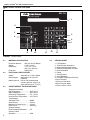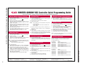
1
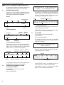
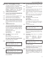
ROBERTS GORDON ® BZC 700 CONTROLLER Operation Manual WARNING Improper installation, adjustment, alteration, service or maintenance can result in death, injury or property damage. Read the installation and operation manuals thoroughly before installing or servicing this equipment. Installation must be done by an electrician qualified in the installation of control systems for heating equipment. Installer Please take the time to read and understand these instructions prior to any installation. Installer must give a copy of this manual to the owner. Owner Keep this manual in a safe place to provide your serviceman with information should it become necessary. Roberts-Gordon Roberts-Gordon Canada Inc. 1250 William Street P.O. Box 44 Buffalo, New York 14240-0044 Telephone: 716.852.4400 Fax: 716.852.0854 Toll Free: 800.828.7450 241 South Service Road West Grimsby, Ontario L3M 1Y7 Canada Telephone: 905.945.5403 Fax: 905.945.0511 http://www.rg-inc.com Roberts-Gordon Oxford Street Bilston, West Midlands WV14 7EG UK Telephone: +44 (0) 1902 494425 Fax: +44 (0) 1902 403200 © Copyright 2000 Roberts-Gordon 10071600NA Original Issue 01/00 uTABLE OF CONTENTS uTABLE OF FIGURES 1. Introduction . . . . . . . . . . . . . . . . . . . . . . . . . . . . .1 ® 1.1 What is a ROBERTS GORDON BZC Controller . . . . . . . . . . . . . . . . . . . . .1 1.2 General Requirements . . . . . . . . . . . . . . . .1 1.3 Safety . . . . . . . . . . . . . . . . . . . . . . . . . . . .1 Figure 1 Figure 2 Keypad Layout . . . . . . . . . . . . . . . . . . . . . .2 ROBERTS GORDON® BZC Controller Quick Programming Guide . . . . . . . . . . . . . . . . . .3 2. Specifications . . . . . . . . . . . . . . . . . . . . . . . . . . . .2 2.1 2.2 2.3 2.4 Material Specification . . . . . . . Electrical Specification . . . . . . . Preset Default Factory Settings Keypad Layout . . . . . . . . . . . . . . . . . . . . . . . . . . . . . . . . . . . . . . . . . . . . . .2 .2 .2 .2 3. Viewing Screen Displays . . . . . . . . . . . . . . . . . . .4 3.1 Information Screens . . . . . . . . . . . . . . . . .4 3.2 Temperatures Sensed by Zone . . . . . . . . .4 3.3 Hours Run . . . . . . . . . . . . . . . . . . . . . . . . .4 4. Programming Options . . . . . . . . . . . . . . . . . . . . .5 4.1 4.2 4.3 4.4 4.5 4.6 4.7 4.8 4.9 4.10 4.11 4.12 4.13 Correcting Wrong Entries . . . . . . . . Temperature Setting . . . . . . . . . . . Switching Times . . . . . . . . . . . . . . Manual Override Temperature . . . . Manual Override Time . . . . . . . . . . Holiday Periods . . . . . . . . . . . . . . . Holiday Mode . . . . . . . . . . . . . . . . Change the Current Time and Date Seasonal Time Adjustment . . . . . . How to Enter Zone Titles . . . . . . . . How to Clear Memory . . . . . . . . . . Changing the Security Code . . . . . Changing the Override Limits . . . . . . . . . . . . . . . . . . . . . . . . . . . . . . . . . . . . . . . . . . . . . . . . . . . . . . . . . . . . . . . . . . . . . . .5 .5 .5 .6 .6 .7 .7 .8 .8 .8 .8 .9 .9 5. The ROBERTS GORDON® BZC 700 Controller Warranty . . . . . . . . . . . . . . . . . . . . . . . .11 © 2000 All rights reserved. No part of this work covered by the copyrights herein may be reproduced or copied in any form or by any means - graphic, electronic, or mechanical, including photocopying, recording, taping or information storage and retrieval systems - without the written permission of Roberts-Gordon. Printed in the U.S.A. SECTION uSECTION 1.1 1: INTRODUCTION WHAT IS A ROBERTS GORDON® BZC CONTROLLER? The ROBERTS GORDON® BZC 700 is a micro processor based controller designed for the most efficient control of CORAYVAC®, VANTAGE®, GORDONRAY® and CARIBE® heaters. The control is capable of giving control outputs from 9 relays, 7 of which afford heating zone control capabilities. The control also features 8 inputs which are used for signal condition monitoring. 1.2 GENERAL REQUIREMENTS The ROBERTS GORDON® BZC series of controllers are supplied pre-configured for their application and only for use with ROBERTS GORDON® infrared heating equipment. Failure to comply with the installation instructions and configuration may invalidate the limited warranty set out on Page 11, Section 5. Mount the ROBERTS GORDON® BZC Controller Quick Programming Guide next to the controller for easy reference of programming steps. See Figure 2, Page 3, Section 2. 1.3 1: INTRODUCTION SAFETY Your Safety is Important to Us! This symbol is used throughout the manual to notify you of possible fire, electrical or burn hazards. Please pay special attention when reading and following the warnings in these sections. WARNING Installation, Service and Annual Inspection of controller must be done by an electrician qualified in the installation of control systems for heating equipment. Installation, Service and Annual Inspection must be done by a contractor qualified in the installation and service of gas-fired heating equipment. Read this manual carefully before installation, operation, or service of this equipment. Failure to follow these instructions can result in death, injury or property damage. For optimum heater performance and safe heating conditions, inspect and maintain heater(s) before every heating season and as necessary. Also, know and maintain heater clearances to combustibles, see heater Installation, Operation and Service manual for further details. If you require additional manuals, contact your ROBERTS GORDON® independent distributor or Roberts-Gordon at (716) 852-4400 or (800) 828-7450 in the U.S., (905) 945-5403 in Canada or at www.rg-inc.com. 1 ® ROBERTS GORDON BZC 700 OPERATION MANUAL uSECTION 2: SPECIFICATIONS BZC 700 Quality in Any Language TM 1 2 3 HOLS VIEW 4 U.S.A. Canada U.K. Internet 0 1 2 3 4 8 5 9 6 7 ENTER DEL RUN PROG OVER RIDE SCROLL 5 6 7 1.716.852.4400 1.905.945.5403 +44 (0) 1902 494425 www.rg-inc.com WARNING: Disconnect from electrical supply before removing this cover 8 9 10 11 12 13 FIGURE 1 - Keypad Layout 2.1 MATERIAL SPECIFICATION Enclosure Material: Weight: Dimensions: Protection: 2.2 ABS (UL 94-5VA Rated) 3.5 lbs (1.6 Kg) 7.9" x 2.4" x 11.4" 199 x 62 x 290 mm Rating IP20 ELECTRICAL SPECIFICATION Supply: Relay Outputs: 120/230V AC ± 10% 50/60Hz Single pole 4.4A 120V AC (resistive) Battery Back-up: Lithium cell maintains data memory and time clock for 10 years minimum at 77°F (25°C) 2.3 PRESET DEFAULT FACTORY SETTINGS Temperature Settings: Day Temperature ........................68°F (20°C) Night Temperature ......................58°F (04°C) Override Up Temperature ..........5°F (02°C) Override Down Temperature ......18°F (04°C) Time Settings: Switching Times ........................NONE Override Limit ............................8 hours Maximum Pre-heat Hours ..........3 hours Date Format ..............................dd/mm/yy Optional Settings: HILO Switching Differential ........0°F Security Codes: Operators....................................0000 2 2.4 KEYPAD LAYOUT 1. LCD Readout 2. View Technical Information 3. Manual Holiday Mode Setting 4. Increase Temperature Set Point 5. Enter Information 6. Delete 7. Scroll Forward 8. Scroll Backward 9. Decrease Temperature Set Point 10.Scroll Forward 11.Return to Run Mode 12.Enter Program Mode 13.Time Override a Zone FIGURE 2 - ROBERTS GORDON® BZC Controller Quick Programming Guide ROBERTS GORDON® BZC Controller Quick Programming Guide Read each section carefully before following the programming instructions. 1. DAY and NIGHT Temperature Settings 1.1 1.2 1.3 1.4 1.5 1.6 1.7 1.8 1.9 From the "Normal Run Mode". Press PROG. Enter the Operators Code 0000 - Press ENTER. Choose 1 for Data. Enter the Zone Number you wish to alter. Enter the required DAY temperature (in degrees C or F as prompted). Enter new temperature using the numeric keypad - Press ENTER. Enter the required NIGHT temperature (in degrees C or F as prompted). Enter new temperature using the numeric keypad - Press ENTER. The screen will now display switching times. If you wish to alter switching times, go to 2.6. To accept the settings entered and exit the programming mode, press RUN to return to the menu. Press RUN again to return to the "Normal Run Mode". 2. Switching Times 2.1 2.2 2.3 2.4 2.5 From the "Normal Run Mode". Press PROG. Enter the Operators Code 0000 - Press ENTER. Choose 1 for Data. Enter the zone number you wish to alter. Accept DAY and NIGHT temperatures by pressing ENTER (refer to 1.5 if you wish to alter the temperatures). NOTE: Each zone must be programmed individually for up to four ON/OFF periods per day. Each period is defined by START and END times. 24 hour clock must be used throughout. 3.1 From the "Normal Run Mode". 3.2 Press the OVERRIDE key to enter the Override program. Enter a security code if required. 3.3 Enter the zone you wish to put into an Override. 3.4 Select 1 ON or 2 OFF. NOTE: 1) ON - heating in the zone will operate to the required DAY temperature. 2) OFF- heating in the zone will be in the NIGHT set back condition. 3.5 Enter the number of hours you wish to override. e.g. :01 The preset maximum number of hours is displayed in brackets. 3.6 Press ENTER. 3.7 When selection is complete, scrolling to the next screen (using the scroll key) in run mode will activate the override. 3.8 To end override before the set time is reached, repeat steps 3.1 to 3.5 and set the override Period to :00. 4. Override Temperature 4.1 From the "Normal Run Mode". 4.2 Pressing the UP and DOWN ARROW KEYS allows you to increase or decrease the set point for any given zone within pre-set limits. 5. Current Time and Date 5.1 5.2 5.3 5.4 5.5 5.6 5.7 5.8 6.1 From the "Normal Run Mode". 6.2 When adjustment is required depress the “1” key for a period of 5 seconds. Adjustment will be made automatically. 7. Holiday Periods 7.1 From the "Normal Run Mode". 7.2 Press PROG. Enter the Operators Code 0000 - Press ENTER. 7.3 Choose 4 for Holidays. The control can be programmed for 5 holiday periods. 7.4 Enter a start date. Enter a date using the date format selected (e.g. dd/mm/yy or mm/dd/yy) - Press ENTER. 7.5 Enter the length in number of days. e.g. 05. - Press ENTER. 7.6 Repeat this for each holiday period to be set. 7.7 The Control will be returned to the Data Menu. 7.8 Press RUN to return to the "Normal Run Mode" NOTE: During the holiday period all the zones will operate at NIGHT set back temperature. 8. Further Information Further programming and set up instructions can be found in the Operation, Installation and Service manuals listed below: 8.1 North America 120V Part Number 10031600NA 10011601NA 10031600NA 10031601NA 10071600NA 10071601NA Manual BZC100 BZC100 BZC300 BZC300 BZC700 BZC700 Operation manual Installation and Service manual Operation manual Installation and Service manual Operation manual Installation and Service manual Manual BZC100 BZC100 BZC300 BZC300 BZC700 BZC700 Operation manual Installation and Service manual Operation manual Installation and Service manual Operation manual Installation and Service manual 8.2 Europe 230V Part Number 10031600UK 10011601UK 10031600UK 10031601UK 10071600UK 10071601UK 3 Roberts-Gordon Roberts-Gordon Canada Inc. Roberts-Gordon 1250 William Street, PO Box 44, Buffalo, NY, 14240-0044, USA. Tel: 716.852.4400 Fax: 716.852.0854 Toll Free: 800.828.7450 © 241South Service Road West, Grimsby, Ontario, L3M 1Y7, Canada. Tel: 905.945.5403 Fax: 905.945.0511 Toll Free: 800.663.9025 P i t d i th U S A Oxford Street, Bilston, West Midlands WV14 7EG UK Tel: +44 (0) 1902 494425 Fax: +44 (0) 1902 403200 P/N 10001600 2: SPECIFICATIONS 5.9 From the "Normal Run Mode". Press PROG. Enter the Operators Code 0000 - Press ENTER. Choose 2 for Time. Select the required date format. Press ENTER to accept this setting. The current time will be displayed. Enter a new time, using 24 hour clock notation. Press ENTER. The current Date will be displayed. Enter a new date using the format selected. Press ENTER. The Control will be returned to the Data Menu. Press RUN to return to the "Normal Run Mode". 6. Daylight Savings Time Adjustment SECTION To set 1 time period only. 2.6 Enter the Start Time for period 1. e.g. 08:00 - Press ENTER. 2.7 Enter the End Time for period 1. e.g. 17:00 - Press ENTER. 2.8 Unused periods must display start: 00.00 end: 00.00. 2.9 Periods 1 to 4 programmed for Monday can be copied to Tuesday by pressing the PROG key when Tuesday period 1 is displayed. This can be repeated for each subsequent day. 2.10 To accept the settings entered and to return to the Data Menu at any point, press RUN. 2.11 Press RUN again to return to the "Normal Run Mode". 3. Override Time ® ROBERTS GORDON BZC 700 OPERATION MANUAL uSECTION 3: VIEWING SCREEN DISPLAYS The screen will now show: In Normal (Run) Mode, the following options are available without the entry of a security code: 3.1 1) VIEW MONITOR LOG 2) VIEW SYSTEM CONFIG PRESS <1 - 2> FOR REQUIRED OPTION INFORMATION SCREENS Pressing the LEFT and RIGHT ARROW KEYS will enable you to scroll through the zones one by one. The following screens will be displayed: By selecting 1, the status and recorded temperature for each zone can be viewed for a 24 hour period in 15 minute intervals. The example below is for a layout arranged in five zones. STATUS Day Date Time WED 10-03-97 WEEK 10 Time Alarm/ Logging Inputs 14.15.30 Relay Status Zones 1 to 5 TIME RL OFF ON OFF OFF ON OFF OFF OFF OFF 09:15 SEN 69 66 69 70 67 ?? ?? ?? ?? INPUTS:CLEAR COMMS: Temperature Recorded Week Number Use the left and right scroll keys to view the incremental information recorded. Communications Status ZONE INFORMATION Press RUN to return to menu and press RUN again to return to Normal (Run) Mode. Actual Operating Zone Temp. Status Zone Title HEATING ZONE NO1 HEAT ON (68) : 64 STATUS:DAY Scroll to the zone to be viewed. By keeping the VIEW button pressed, it will show technical information such as minimum/maximum temperature and hours run etc. for the zone displayed. Maximum Minimum Minimum Day Temp. Day Temp. Night Temp. HEATING ZONE NO 1 DMAX69 OOT06.30 RSP07.00 MPH03 Optimiser On time DMIN66 NMIN56 ROC03 HR07.21 Reached Maximum Rate of Set Point Pre-heat Change Hours Run In Normal (Run) Mode, the following options are available with the entry of a security code: 3.2 TEMPERATURES SENSED BY ZONE FOR 24 HOUR PERIOD Press PROG and enter the code 1805. Press ENTER. Enter 4 for MONITOR. 4 HOURS RUN Press PROG and enter the code 1805. Press ENTER. Enter 5 for HOURS RUN. By selecting the hours run mode, the recorded running hours for the previous four weeks for each relay can be viewed. Heating Required ON/OFF Zone Temp. FURTHER ZONE INFORMATION Zone Title 3.3 PLEASE ENTER THE NUMBER THAT YOU WISH TO VIEW (1-9) Enter the relay number to be viewed, the subsequent display will be as follows: Week # WEEK HOURS RUN 04 36.05 03 42.50 02 35.90 01 33.04 # Running Hours Press ENTER to return to selection screen. To view another zone, repeat the steps above. Press RUN to return to menu and press RUN again to return to Normal (Run) Mode. SECTION uSECTION 4: PROGRAMMING OPTIONS The display of temperature on the screens in these programming instructions is in Fahrenheit. The following instructions cover the programming options for normal daily use. Please consult the ROBERTS GORDON® BZC 700 Controller Installation Manual for initial set up information. 4.1 CORRECTING WRONG ENTRIES 4.1.1 If a wrong entry is made during the programming sequence, continue following the instructions until the prompt returns to the menu. 4.1.2 The entry can be corrected by repeating the programming sequence from the beginning. 4.1.3 Skip each correct screen by pressing ENTER. 4.1.4 When the incorrect entry is reached, type in the correct entry and press ENTER. Continue pressing ENTER to skip any following correct screens until the instructions direct you to return to the menu screen. 4.2 TEMPERATURE SETTING 4.2.1 The screen will now display switching times. If you wish to alter switching times, go to Page 5, Section 4.3.2. 4.2.5 To accept the settings and return to the DATA menu, press RUN. 4.2.6 To alter the set points for further zones, repeat the steps on Page 5, Sections 4.2.1 to 4.2.3. 4.2.7 If any mistakes were made during the programming sequence, see Page 5, Section 4.1 for corrective action. When all the zones are correctly programmed, return to Normal (Run) Mode by pressing RUN. 4.3 SWITCHING TIMES 4.3.1 Press PROG and enter the code 0000. Press ENTER. Enter 1 for DATA. Enter the zone number you wish to alter. Press ENTER to accept DAY and NIGHT temperatures. To alter the temperatures, see Page 5, Section 4.2. 4.3.2 The screen will now show: ENTER SWITCHING TIMES FOR PERIOD 1 MON START: 00.00 END: 00.00 Enter required switching times for Monday period 1. 68°F or 20°C 58°F or 04°C Press PROG and enter the code 0000. Press ENTER. Enter 1 for DATA. Enter the zone number you wish to alter. Each zone can have individual time and temperature settings, therefore this procedure must be repeated for each zone to be altered. 4.2.2 OPTIONS 4.2.4 There are two temperature settings for each zone. One setting is for the DAY temperature. This will be the set point temperature when the switching time is ON. One setting is for the NIGHT temperature. This will be the set point temperature when the switching time is OFF. Default Temperature Settings: Day Temperature Night Temperature 4: PROGRAMMING The screen will now show: There are four switching periods per day for each individual zone. 4.3.3 The following example allows for one switching period per day. Monday to Friday START 08:00 END 17:00 Saturday START 08:00 END 12:00 Sunday NO SWITCHING PERIOD 4.3.4 The screen will now show: ENTER SWITCHING TIMES FOR PERIOD 1 MON START: 00.00 END: 00.00 ENTER THE REQUIRED 'DAY' TEMPERATURE (OCCUPANCY PERIOD, e.g. 68°F) : 68 Enter start time 0800. Press two digits for the required temperature and then press ENTER. 4.2.3 The screen will now show: ENTER THE REQUIRED 'NIGHT' TEMPERATURE (SETBACK OR FROST, e.g. 58°F) : 58 Press two digits for the required temperature and then press ENTER. Use 24 hour clock notation for the start of DAY TEMPERATURE (mistakes may be rectified by pressing DEL) and then press ENTER. NOTE: When entering a start time, it is not necessary to allow a warm-up period prior to the start of the required day temperature. This is automatically calculated by the ROBERTS GORDON® BZC 700 Controller giving the required temperature at the time set. 5 ® ROBERTS GORDON BZC 4.3.5 700 OPERATION MANUAL The screen will now show: The screen will now show: ENTER SWITCHING TIMES FOR PERIOD 1 MON START: 08.00 END: 00.00 ENTER SWITCHING TIMES FOR PERIOD 1 SAT START: 08.00 END: 00.00 Enter end time 1700. Enter end time 1200. The screen will now show: The screen will now show: ENTER SWITCHING TIMES FOR PERIOD 1 SAT START: 08.00 END: 12.00 ENTER SWITCHING TIMES FOR PERIOD 1 MON START: 08.00 END: 17.00 Press ENTER. Leave the start and end times blank for periods 2, 3 and 4 because in this example we are only using one switching period on Saturday. Press ENTER. 4.3.6 The screen will now show: ENTER SWITCHING TIMES FOR PERIOD 2 MON START: 00.00 END: 00.00 As no switching times are required for Sunday, press RUN to save the settings and return to the menu. The process described above must now be repeated for each heating zone to be altered. Press ENTER, to skip without altering the setting. The reason for leaving the start and end times blank is because in this example we are only using one switching period per day. Repeat as above for periods 3 and 4 for Monday. 4.3.7 The screen will now show: ENTER SWITCHING TIMES FOR PERIOD 1 TUE START: 00.00 END: 00.00 4.3.10 If any mistakes were made during the programming sequence, see Page 5, Section 4.1 for corrective action. 4.3.11 Press RUN to return to Normal (Run) Mode. NOTE: If remote time enable is to be used, leave all switching periods set to 00.00. 4.4 MANUAL OVERRIDE TEMPERATURE 4.4.1 To manually override temperature, first use the left and right arrow keys to display the zone you wish to alter. Pressing the PROG key at this point will copy all of Monday’s switching times to Tuesday. 4.3.8 Example for zone 1 is shown below: The screen will now show: HEATING ZONE NO1 HEAT ON ENTER SWITCHING TIMES FOR PERIOD 1 WED START: 00.00 END: 00.00 Pressing the PROG key at this point will copy the times from Tuesday to Wednesday. Repeat this for Thursday and Friday. 4.3.9 The screen will now show: ENTER SWITCHING TIMES FOR PERIOD 1 SAT START: 00.00 END: 00.00 For Saturday, the switching period is different from the weekday settings. The new settings must be entered. Enter start time 0800, Press ENTER. 6 (70) : 67 STATUS:DAY The set point temperature appears in the brackets. 4.4.2 Pressing the UP and DOWN ARROW KEYS will increase or decrease the set point (in increments of 1O) for the displayed zone within pre-set limits. NOTE: Changing the set point for the daytime temperature manually will only apply to the current switching period. 4.5 MANUAL OVERRIDE TIME 4.5.1 From the Normal (Run) Mode, press the OVERRIDE key to enter the override program. Enter a security code if prompted. Override will allow the heating system to be switched to day or night mode manually. SECTION 4.5.2 The screen will now show: 4.6.2 PLEASE ENTER THE NUMBER OF THE ZONE YOU WISH TO OVERRIDE (1-7) OPTIONS The screen will now show: PLEASE ENTER HOLIDAY PERIOD NUMBER 1 START DATE: 00 - 00 - 00 LENGTH: 00 Select the zone required to be overridden. 4.5.3 4: PROGRAMMING Enter the date in the format selected under the time function (dd-mm-yy or mm-dd-yy). The screen will now show: Enter length (number of days duration of holiday). DO YOU WANT TO OVERRIDE THE ZONE 1) ON (DAY TEMP.) OR 2) OFF (NIGHT TEMP.) 4.6.3 The DEL key may be used to correct mistakes. Press ENTER when correct. 4.6.4 If any mistakes were made during the programming sequence, see Page 5, Section 4.1 for corrective action. 4.6.5 Press RUN to return to Normal (Run) Mode. Press 1 to select on (day settings) or 2 to select off (night settings). 4.5.4 The screen will now show: PLEASE ENTER THE REQUIRED OVERRIDE PERIOD (08 HOURS MAXIMUM) : 00 Enter the number of hours you wish to override the zone for example :01. The number in brackets is the maximum number in hours of the override period. This figure is preset and can only be altered by an authorized user. 4.5.5 NOTE: If ENTER is pressed at any display, then the current setting will be retained. NOTE: To cancel a holiday period in progress, repeat 4.6.1 to 4.6.3 changing the period in progress to 00 length. 4.7 HOLIDAY MODE 4.7.1 Pressing HOLS will give you the option to manually initiate a new holiday period. 4.7.2 The screen will now show: The DEL key may be used to correct mistakes, press ENTER when correct. You will now see the operating status for the zone change to either OR N01 (night status) or OR D01 (day status). ARE YOU SURE YOU WANT TO SWITCH ON HOLIDAY MODE (PRESS ENTER FOR YES) 4.5.6 When selection is complete, scrolling to the next screen in run mode will activate the override command. Pressing ENTER at this point will switch all zones to the night setback temperature. 4.5.7 To end override before the set time is reached, reenter override mode and set the override period to :00. 4.6 4.7.3 HOLIDAY PERIODS There are two options available on the ROBERTS GORDON® BZC 700 Controller for setting holiday periods. The first is to pre-program known holiday periods. This sequence is described below. The second described under HOLIDAY MODE can be used to manually set holiday periods. 4.6.1 Pressing any other key will return you to the status screens without starting a holiday period. When the holiday period is on, the zone status screens will show: HEATING ZONE NO1 HEAT OFF 4.7.4 (58) : 62 STATUS: HOLS At the end of the holiday period, press the HOLS key to return to normal switching times. From the Normal (Run) Mode: The screen will now show: Press PROG and enter the code 0000. Press ENTER. Enter 4 for HOLS. ARE YOU SURE YOU WANT TO SWITCH OFF HOLIDAY MODE (PRESS ENTER FOR YES) Five periods can be preset by entering the start date and then the number of days the holiday lasts. Press ENTER to end the holiday period. 7 ® ROBERTS GORDON BZC 700 OPERATION MANUAL 4.8 CHANGE THE CURRENT TIME AND DATE 4.8.1 Press PROG and enter the code 0000. Press ENTER. Enter 2 for TIME. 4.8.2 4.10.2 The screen will now show: 1) ZONE TITLE 2) ALARM 3) RELAY TITLE PRESS 1 - 3 FOR REQUIRED OPTION The screen will now show: ENTER THE DATE FORMAT FOR THE DISPLAY d-m-y <00> m-d-y <01> :00 Enter 1 for zone title. You will be asked for the zone number you want to alter. 4.10.3 The screen will now show: 0123456789:;(=)?@ABCDEFGHIJKLMNOPQRSTUVW XYZ ENTER THE TITLE HEATING ZONE NO1 Enter 01 and press ENTER to change the date format to month/day/year. Alternatively, enter 00 and press ENTER to change the date format to day/month/year. 4.8.3 If the title that is displayed is correct, pressing ENTER will return you to the main menu. If the title is incorrect, using the left and right ARROW KEYS to select a letter and the ENTER key will enable you to build up a new title. The maximum number of characters is 16. A space is entered by selecting the blank after the Z. The screen will now show: THE CLOCK IS NOW SET AT : 14: 15 PLEASE ENTER A NEW TIME : 4.8.4 Enter a new time in (Hours: Minutes) in 24 hour clock notation. 4.10.4 Press RUN to return to Normal (Run) Mode. Mistakes may be rectified by pressing DEL. Press ENTER when new time is correct. 4.10.5 If any mistakes were made during the programming sequence, see Page 5, Section 4.1 for corrective action. The screen will now show: THE DATE IS NOW SET AT : 12 - 10 - 10 PLEASE ENTER A NEW DATE : - Dates must be entered in the format selected. See Page 8, Section 4.8.2. Press ENTER when correct and the display will return to the Set-Up Menu. 4.8.5 Press RUN to return to Normal (Run) Mode. If any mistakes were made during the programming sequence, see Page 5, Section 4.1 for corrective action. 4.9 SEASONAL TIME ADJUSTMENT 4.9.1 Pressing the number one button and holding it down for 5 seconds during the months of March or April and October will give automatic seasonal correction. 4.10 HOW TO ENTER ZONE TITLES 4.10.1 Press PROG and enter the code 1805. Press ENTER. Enter 2 for TITLES. 4.11 HOW TO CLEAR MEMORY This facility will clear the logs of the hours run and monitor data. 4.11.1 Press PROG and enter the code 1805. Press ENTER. Enter 6 for CLEAR MONITOR. 4.11.2 The screen will now show: THIS WILL DELETE ALL LOGGING AND ALARM MEMORY !!! PRESS (DEL) TO CONTINUE Press the DEL key and a prompt for the passcode will appear. Pressing any other key will abort the process. 4.11.3 The screen will now show: A SECURITY CODE IS REQUIRED TO PROGRAM THIS UNIT. Please enter the code: 0376 Enter the code 0376 and press ENTER. 4.11.4 Press RUN to return to Normal (Run) Mode. 8 SECTION 4.12 CHANGING THE SECURITY CODE 4.13 4: PROGRAMMING OPTIONS CHANGING THE OVERRIDE LIMITS 4.12.1 Press PROG and enter the code 0000. Press ENTER. Enter 3 for CODE. 4.13.1 Press PROG and enter the code 1805. Press ENTER. Enter 1 for SETUP. 4.12.2 This is the section used to set the security code. 4.13.2 These are the settings for limit of the override for both time and temperature. The screen will now show: The screen will now show: WHICH CODE DO YOU WISH TO ALTER? 1) MANAGER CODE 2) OVERRIDE CODE Pressing '1' will allow you to change the Manager Code (Page 9, Section 4.12.3) for programming the unit. Pressing '2' will allow you to change Override Code (Page 9, Section 4.12.5). 4.12.3 Manager Code ENTER CALIBRATION SETTING NUMBER 1 (10) THE SENSOR IS NOW READING :65 F Press ENTER to skip the calibration screens. There will be one displayed for each zone. The calibration of the sensors will be conducted by installer. 4.13.3 The screen will now show: The screen will now show: THE OLD ‘USER’ SECURITY CODE WAS : 0000 PLEASE ENTER A NEW CODE (4 DIGITS) : 0000 Enter 4 digits for the new code (only asterisks will be shown when entering code). 4.12.4 Press RUN to return to Normal (Run) Mode. 4.12.5 Override Code The default maximum override of 8 hours is displayed. To alter the number, enter the new number and press ENTER. 4.13.4 The screen will now show: ENTER THE TEMPERATURE OFFSET UPPER LIMIT YOU WANT FROM THE UP BUTTON. :05 The screen will now show: ENABLE OVERRIDE CODE? <00> NO <01> YES ENTER THE MAXIMUM OVERRIDE HOURS FOR THE OVERRIDE BUTTON (00 = DISABLED) :08 :01 Selecting '00' here will allow you to override the time without needing a code. Selecting '01' will not allow you to override the time without knowing the security code. The default upper offset limit of 5O Fahrenheit is displayed. To alter the number, enter the new number and press ENTER. 4.13.5 The screen will now show: ENTER THE TEMPERATURE OFFSET UPPER LIMIT YOU WANT FROM THE DOWN BUTTON. :18 4.12.6 Enter a new four digit code. 4.12.7 Press RUN to return to Normal (Run) Mode. NOTE: In the event that the code is forgotten, contact your ROBERTS GORDON® independent distributor or Roberts-Gordon at (716) 852-4400 or (800) 8287450 in the U.S., (905) 945-5403 in Canada or at www.rg-inc.com. The default upper offset limit of 18O Fahrenheit is displayed. To alter the number, enter the new number and press ENTER. 4.13.6 If any mistakes were made during the programming sequence, see Page 5, Section 4.1 for corrective action. 4.13.7 At the prompt for a zone to alter, press RUN to return to the menu. 4.13.8 Press RUN again to return to Normal (Run) Mode from the menu. 9 SECTION 5: THE ROBERTS GORDON® BZC 700 CONTROLLER WARRANTY uSECTION 5:THE ROBERTS GORDON® BZC 700 CONTROLLER WARRANTY ROBERTS-GORDON WILL PAY FOR: For 36 months from the date of purchase by the original consumer or 42 months from date of shipment by RobertsGordon, whichever occurs first: we will provide, free of charge, replacement parts for any part of the ROBERTS GORDON® BZC 700 Controller that fails because of a manufacturing or material defect. ROBERTS GORDON® replacement parts are warranted for the period of the original ROBERTS GORDON® BZC 700 Controller Warranty. ROBERTS-GORDON WILL NOT PAY FOR: Service trips, service calls and labor charges. Shipment of replacement parts. Damage due to: Failure to install, operate or maintain the ROBERTS GORDON® BZC 700 Controller as directed in Installation and Operation Manuals. You must follow requirements printed in these manuals. Misuse, abuse, neglect or modification of the ROBERTS GORDON® BZC 700 Controller in any way. Improper service, use of replacement parts or accessories that are not specified by Roberts-Gordon. Improper installation, or any relocation of the ROBERTS GORDON® BZC 700 Controller after initial installation. Incorrect supply, accident, fire, flood, acts of God or other casualty. Use of the ROBERTS GORDON® BZC 700 Controller for other than its intended purpose. Use of the ROBERTS GORDON® BZC 700 Controller in a corrosive atmosphere or any atmosphere containing contaminants. Shipping. Claim must be filed with carrier. WARRANTY IS VOID IF: The ROBERTS GORDON® BZC 700 Controller is not installed by a electrician qualified in the installation of control systems for heating equipment. You cannot prove original purchase date and required annual maintenance history. READ YOUR INSTALLATION MANUAL If you have questions about your ROBERTS GORDON® BZC 700 Controller, contact your installing professional. Should you need replacement parts or have additional questions, call or write Roberts-Gordon: U.S.A. 1250 William Street P.O. Box 44 Buffalo, New York 14240-0044 Telephone: 716.852.4400 Fax: 716.852.0854 Canada 241 South Service Road, West Grimsby, Ontario L3M 1Y7 Telephone: 905.945.5403 Fax: 905.945.0511 On the web at: www.rg-inc.com Roberts-Gordon's liability, and your exclusive remedy, under this warranty or any implied warranty (including the implied warranties of merchantability and fitness for a particular purpose) is limited to providing replacement parts during the term of this warranty. Some jurisdictions do not allow limitations on how long an implied warranty lasts, so this limitation may not apply to you. There are no rights, warranties or conditions, expressed or implied, statutory or otherwise, other than those contained in this warranty. Roberts-Gordon shall in no event be responsible for incidental or consequential damages or incur liability for damages in excess of the amount paid by you for the ROBERTS GORDON® BZC 700 Controller. Some jurisdictions do not allow the exclusion or limitation of incidental or consequential damages, so this limitation or exclusion may not apply to you. This warranty gives you specific legal rights, and you may also have other rights which vary from jurisdiction to jurisdiction. Roberts-Gordon shall not be responsible for failure to perform under the terms of this warranty if caused by circumstances out of its control, including but not limited to fire, flood, strike, government or court orders, unavailability of supplies, parts or power. No person is authorized to assume for Roberts-Gordon any other warranty, obligation or liability. LIMITATIONS ON AUTHORITY OF REPRESENTATIVES: No representative of Roberts-Gordon, other than an Executive Officer, has authority to change or extend these provisions. Changes or extensions shall be binding only if confirmed in writing by Roberts-Gordon's duly authorized Executive Officer. The data plate and/or serial number are removed, defaced, modified or altered in any way. The ROBERTS GORDON® BZC 700 Controller is transferred. This warranty is nontransferable. Roberts-Gordon is not permitted to inspect the damaged ROBERTS GORDON® BZC 700 Controller and/or component parts. 11 SECTION#: 13