1
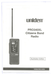
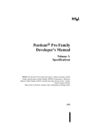
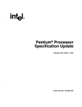
NHRC-4/M2 Installation and Setup Guide Hardware Version: Rev. B. Guide Version: 2005-Aug-31 Copyright Notice Copyright 2000, 2001, 2005, by NHRC LLC This document contains proprietary information, which is the confidential property of NHRC LLC. No part of this document may be used or reproduced, by any means, or for any purpose, without the expressed written consent of NHRC LLC. No part of this document should be considered to be specifications for the proper or correct operation of the NHRC-4/M2 Repeater Controller. In no way will NHRC LLC be liable for direct or indirect damages to the controller or attached equipment. Printed in the U.S.A. Thank You! Thank you for purchasing the NHRC-4/M2 Repeater Controller. This controller has been designed using the very latest state-of-the-art technology. Please review this manual carefully before putting your controller into operation. This manual represents a very large documentation effort. Your comments are important to us. If you find an error or find any passages that are not clearly understandable we would like to hear about it. Please send your comments to [email protected]. Support for the controller is available by email or telephone. Please direct softwarerelated questions via email to [email protected]. Please direct hardware-related questions via email to [email protected] . Your question(s) will be answered promptly. Questions of a more urgent nature can be answered by telephone support. Telephone support is available Monday through Friday, from 6 PM until 10 PM, Eastern Time. Table Of Contents 1. INTRODUCTION ................................................................................................................................2 2. INSTALLATION..................................................................................................................................2 2.1 PRIMARY RADIO PORT CONNECTIONS ............................................................................................2 2.1.1 Option 1: Use an interface cable...............................................................................................2 2.1.2 Option 2: Modify the MASTR II System Board. ........................................................................3 2.2 SECONDARY RADIO PORT WIRING..................................................................................................4 2.3 TS-32/TS-64 HOOKUP ....................................................................................................................5 2.3.1 TS-64 Notes ...............................................................................................................................5 2.3.2 TS-32 Notes ...............................................................................................................................6 3. INSTALLING THE NHRC-4/M2 INTO THE MASTR II...............................................................7 3.1 3.2 3.3 3.4 4. APPENDICES.....................................................................................................................................10 4.1 5. THE LED STATUS INDICATORS.......................................................................................................7 INSTALLING THE NHRC-DAD WITH THE NHRC-4/M2..................................................................7 USING THE DIGITAL OUTPUT ..........................................................................................................8 ADJUSTING THE AUDIO LEVELS ......................................................................................................8 TERMINOLOGY AND ABBREVIATIONS ...........................................................................................10 CIRCUIT BOARD .............................................................................................................................11 5.1 INTERCONNECTIONS .....................................................................................................................11 6. SCHEMATICS ...................................................................................................................................12 7. PARTS LIST .......................................................................................................................................15 NHRC LLC LIMITED WARRANTY ......................................................................................................17 Copyright 2001, 2005, NHRC LLC. All Rights Reserved. Page i NHRC-4/M2 User Guide 1. Introduction This manual describes how to install and set up the NHRC-4/M2 repeater controller. This manual should be used in conjunction with the NHRC-4 Operating Manual, which describes the programming and operation of the controller. 2. Installation This section of the User Guide describes the electrical interfaces used to connect the controller to: • Power and primary repeater (the GE MASTR II), • Link/Remote Base radio • Communications Specialists TS-64 CTCSS Encoder/Decoder • Optional NHRC-DAD digital audio delay board(s). It is intended for the repeater operator to use in the planning and installation of the NHRC4/M2 Repeater Controller into a repeater system. The controller is designed to be installed inside of a GE MASTR II mobile or station. The controller is installed onto the connectors that GE intended for the “channel guard” board. CTCSS is supported with an optional CommSpec TS-64. All of the controller’s signals, for the primary and secondary radios, as well as the digital output are presented at either J908 or J909. 2.1 Primary Radio Port Connections The NHRC-4/M2 operates using the MASTR II as the "primary" radio. The primary radio must operate in full-duplex mode. If your MASTR II is not already converted for full-duplex operation, consult the NHRC WWW MASTR II Info-site Full Duplex Conversion for duplexing information. There are two options for interfacing the CAS and TX audio to the controller. These signals do not normally appear on the P908 plug on the system board of the MASTR II. You can either use an interface cable, or you can modify the 2.1.1 Option 1: Use an interface cable Transmit audio and CAS appear on the controller at J1, a 3-pin header. Wire an interface cable as shown in the table below: J1 Connections J1 Pin # 1 2 3 Page 2 MASTR II Signal MIC HI J902 #6 CAS J904 #9 MIC LO J902 #5 Copyright 2001, 2005, NHRC LLC. All Rights Reserved. NHRC-4/M2 User Guide 2.1.2 Option 2: Modify the MASTR II System Board. By cutting one trace and adding two wires to the MASTR II system board, the jumper described in option 1, above, can be avoided. Add a wire that connects P908 pin 2 to J902 pin 6 (the exciter's MIC HI input). Cut the trace that leads to P908 pin 3 on the system board, and add a wire that connects P908 pin 3 to J904 pin 9 (the CAS signal from the IFAS board). Install 0 ohm resistors (jumpers) R22 and R38 on the NHRC-4/M2 board, enabling the TX audio and CAS signals on the J908 connector. Note that these jumpers may already be populated on your board. If you plan on using the local microphone on the MASTR II's control head, install a 1.5K resistor in location R38. P908 Primary Radio Port Connections P908 Pin # 1 2 Discriminator Audio Transmit Audio 3 CAS 4 5 6 7 10V Regulated no connection PTT CG Encode Delayed PTT Ground 9 NHRC-4/M2 Use System Board Modification Add Wire to MIC HI On Exciter (J902-6) Cut existing trace to P908-3. Add Wire to CAS on IFAS (J904-9) Copyright 2001, 2005, NHRC LLC. All Rights Reserved. Page 3 NHRC-4/M2 User Guide 2.2 Secondary Radio Port Wiring The controller provides the secondary radio port on the F3 through F8 frequency select leads, using the P909 connector. These leads are routed to the front panel control cable connector on the systems board. In mobile MASTR II radios, these control lines are sometimes subject to the installation of diodes and jumpers and cutting of traces to share channel elements across more than one channel selection. These diodes and jumpers must be removed, and the cut traces must be jumpered to for proper operation of the controller. Consult the MASTR II service manual for information on these jumpers. Dissecting an old control cable makes an easy job of attaching your secondary radio to the MASTR II. In an E-chassis MASTR II, a bit of clever wiring in the systems board can allow a repeater on the "top deck" and the secondary, remote-base radio on the "bottom deck". In base stations and repeaters, the P909 connector is unused. Individual wires must be attached to P909 to break out the secondary radio port. P909 Secondary Radio Port Connections P909 Pin # 1 2 3 4 5 6 7 8 J901 Frequency (control cable) Select Pin # Secondary port CAS F8 15 Secondary port PTT F7 14 Secondary port CTCSS detect F6 13 Secondary port receiver audio F5 12 Secondary port transmitter audio F4 11 Digital output F3 10 no connection F2 9 Unused, ground to select F1 F1 8 NHRC-4/M2 Use It is extremely important that the radio attached to the secondary radio port be provided with a common ground from the MASTR II. The "A-" lead (J901 pin 30) is a good spot. If this common ground is not provided, erratic operation or distorted audio on the secondary radio will result. Also note that the Secondary port CAS requires an active high signal. Consult the NHRC-4/M2 Remote Base Breakout Application note for instructions on converting CAS from active low if an active high signal cannot be supplied. Page 4 Copyright 2001, 2005, NHRC LLC. All Rights Reserved. NHRC-4/M2 User Guide TS-32/TS-64 hookup 2.3 Connector JTS32 is a 7-pin header that allows the easy installation of an optional Communications Specialists TS-32 or TS-64 for CTCSS decode, encode, CTCSS audio filtering, and reverse-burst. (Reverse burst is only available with the TS-64.) Wire JTS32 to the TS-32/TS-64 as follows: JTS32 Connections JTS32 TS-32 Pin # Signal 1 +V POWER 2 CTCSS DECODER INPUT 3 4 5 6 7 Description +10 volts to CTCSS board receiver audio to CTCSS decoder receiver audio to audio filter input TO AUDIO FILTER INPUT (separate lead for TS-64) FROM AUDIO FILTER OUTPUT filtered audio to controller decode signal from CTCSS decoder CTCSS DETECT See important warning below! CTCSS ENCODER OUTPUT CTCSS tone to transmitter - GROUND & HANG-UP Ground WARNING: DO NOT APPLY VOLTAGE TO THE CTCSS DETECT INPUT! This input is pulled low by the CTCSS decoder when CTCSS is NOT PRESENT. It will float high when CTCSS is detected. Application of voltage to this input will destroy Q4 and render the controller inoperative. Damage of this nature is not covered by the NHRC Limited Warranty. The TS-32 and the TS-64 both have a high-pass filter to remove the CTCSS tone from the repeated audio. By removing jumper JP3, the controller's audio can be passed through the audio filter on the TS-32/TS-64. Note: If the audio filter is not used, then jumper JP3 must be installed in order for audio to be passed through the controller. The Communications Specialists CTCSS boards are not supplied by NHRC. Contact Communications Specialists at 800-854-0547 directly to order these boards. 2.3.1 TS-64 Notes Consult the NHRC-4/M2 TS-64 Application note for detailed connection instructions. The TS-64 has a reverse-burst/PTT delay feature that can be used with the NHRC-4/M2. This feature is useful to eliminate the squelch crash received by the user's radio when the repeater transmitter drops. Note that the user's radios must have CTCSS decoding enabled for this to work. The NHRC-4/M2 provides support for the PTT delay through jumper JP4. JP4 pin 1 is the controller's PTT signal, and JP4 pin 2 is PTT to the MASTR II. If the reverse-burst/PTT delay feature is not used, then a jumper must be installed on JP4 so the controller can key the MASTR II. Copyright 2001, 2005, NHRC LLC. All Rights Reserved. Page 5 NHRC-4/M2 User Guide Adjust the CTCSS deviation with R20 on the TS-64 board, with the "CG LEVEL" pot on the MASTR II exciter set to midrange. The ideal deviation for the CTCSS tone is 750 Hz. Consult the TS-64 INSTRUCTION SHEET for details on setting the CTCSS frequency and the reverse burst. 2.3.2 TS-32 Notes The TS-32 must have the JU-2 jumper cut. Use the OUT-2 signal from the TS-32 into the CTCSS detect of the NHRC-4/M2. If you want to be able to disable the CTCSS requirement, install a switch on the HANGUP lead. The TS-32 will supply CTCSS encode tone to the exciter through the NHRC-4/M2. Adjust the CTCSS deviation with the R29 on the TS-32 board, with the "CG LEVEL" pot on the MASTR II exciter set to midrange. The ideal deviation for the CTCSS tone is 750 Hz. Consult the TS-32 INSTRUCTION SHEET for details on setting the CTCSS frequency. Page 6 Copyright 2001, 2005, NHRC LLC. All Rights Reserved. NHRC-4/M2 User Guide 3. Installing the NHRC-4/M2 into the MASTR II The controller installs in the MASTR II where the MASTR II "Channel Guard" board normally belongs, plugged into the top of the systems board in the front of the radio. If you have not already removed the Channel Guard board, do so now by pulling it straight up and out of the radio. The NHRC-4/M2 installs with the component side of the board facing the control head cable connector. Carefully line up the P908 (left side) and P909 (right side) connectors with the pins on the system board. Push the board down firmly until the connectors are right against the system board. The controller is now installed. 3.1 The LED Status Indicators The NHRC-4 repeater controller is equipped with five status LEDS that aid in setup and troubleshooting. There are green LEDs for each radio port that indicate that the controller has getting a valid CAS (carrier operated switch) and, if a CTCSS decoder is connected, a a valid CTCSS decode signal. The appropriate green LED should light when its receiver is active, and, if a CTCSS decoder is present, the correct CTCSS tone is present. The yellow LED indicates that a DTMF signal is being decoded on the primary receiver. This LED should light for the entire duration that the DTMF signal is present on the primary receiver. The red LED's indicates transmit. These LED will light when its respective transmitter is transmitting. The LEDS can be disabled to reduce the power consumption of the controller. Remove jumper JP2 to disable the LEDS. 3.2 Installing the NHRC-DAD with the NHRC-4/M2 J2 Primary Radio DAD J3 Secondary Radio DAD Pin 1 2 3 4 Use +13.8 Volts to delay board Audio to delay board Audio from delay board Ground/Audio Return The audio delay for the primary radio simply plugs in to J2. The audio delay for the secondary radio plugs in to J3. If the audio delay is not installed, a jumper between pins 2 and 3 of the port's delay connector must be installed, or the controller will not pass audio. It is strongly recommended that the CTCSS filter be used, as described above, if both CTCSS encode/decode and the audio delay are used. See the Operation Instructions section on programming the flag bits to tell the controller the delay is present. Copyright 2001, 2005, NHRC LLC. All Rights Reserved. Page 7 NHRC-4/M2 User Guide 3.3 Using the Digital Output The NHRC-4 Repeater Controller has a digital output that can be used for various remote control applications or to control a fan on the repeater's transmitter. The digital output is an open-drain into a power MOSFET, which is capable of sinking quite a bit of current, but we recommend a maximum load of about 500 mA. Use a relay to drive larger loads. The opendrain output can be used to gate the HOOKSWITCH signal to a TS-32 or other CTCSS decoder, to enable or disable CTCSS. Software allows the output to be enabled, disabled, or pulsed. In fan control mode, this output will be turned on when the transmitter is turned on, and turned off a programmable amount of time after the transmitter is turned off. 3.4 Adjusting the Audio Levels Audio Level Adjustments Potentiometer VR1 VR2 VR3 VR4 VR5 VR6 Use Primary Receiver Level Secondary Receiver Mix Level Primary Receiver Mix Level Beep Tone Mix Level Primary Transmitter Master Level Secondary Transmitter Master Level Preset all potentiometers to midrange. Key a radio on the primary input frequency, send some touch-tones, and adjust VR1 (the primary receiver level) until DTMF decoding is reliably indicated by yellow LED D5. Note: If VR1 is set too high, a crackling noise may be heard in the transmitted audio during the hang time. Reduce the level set by VR1 until this noise goes away. Any repeated audio level reduction caused by adjusting VR1 can be compensated for by adjusting VR3 (primary receiver level) or VR5 (primary transmitter output level.) The primary radio's transmit deviation is set with VR5 (the primary transmitter master level) on the controller board and the transmitter's deviation/modulation control. The key to properly adjusting these controls is to remember that the limiter in the transmitter is after VR5 but probably before the transmitter's deviation/modulation control. The transmitter's deviation/modulation control will set the actual peak deviation, and VR5 will set the level into the transmitter. You do not want excessive limiting on normal speech going through the repeater; it sounds bad and tends to "pump-up" background noise. On the other hand, some limiting is desirable. An oscilloscope connected to the audio output of a receiver tuned to the transmitter's frequency will show limiting as the audio gets "flat-topped" or clipped by the limiter. Ideally, a 4.5KHz deviation signal input to the repeater should result in a 4.5 KHz deviation output, and 5.5 KHz of input deviation should result in just under 5.0 KHz of deviation out of the repeater. A service monitor (or two), deviation meter, and/or a signal generator are necessary to do this job right. The secondary radio's transmit deviation is set with VR2 (the secondary transmitter master level). Enable the secondary transmitter, and adjust VR2 for proper transmit deviation, similarly to VR5. Page 8 Copyright 2001, 2005, NHRC LLC. All Rights Reserved. NHRC-4/M2 User Guide Enable the secondary receiver, and adjust VR6 for reasonable deviation on the enabled transmitters when a signal is received on the secondary receiver. Adjust VR4 (the beep level) to set the courtesy tone and CW tone level. VR3 is used to set the primary receiver's audio mix level, and may not need to be adjusted from midpoint. Copyright 2001, 2005, NHRC LLC. All Rights Reserved. Page 9 NHRC-4/M2 User Guide 4. Appendices 4.1 Terminology and Abbreviations Term Description CAS Carrier Activated Squelch, where receipt of a signal, with or without CTCSS tones will activate the controller. CW Continuous Wave signals, commonly using “Morse Code.” The term “CW” refers to the radio emission type, while “Morse Code” refers to the signaling type used. Typically, they are incorrectly used interchangeably. Digital Audio Delay (DAD) Digital Audio Delay (DAD) removes squelch crashes and allows DTMF tones to be fully muted. DTMF Also known as “Touch Tone” codes. ID Identification PTT Push-to-Talk Page 10 Copyright 2001, 2005, NHRC LLC. All Rights Reserved. NHRC-4/M2 User Guide 5. Circuit Board 5.1 Interconnections Connector Name Purpose P908 “REPEATER” P909 “REMOTE BASE” Connects the secondary repeater transmit and receive audio, PTT, and CAS signals for the radio to the controller. J1 “AUX” Supplies MIC HI and CAS signals for unmodified MASTR Iis (with no system board modifications for the NHRC-4/M2) J2 “DELAY” Connects power and audio signals for operation of the Digital Audio Delay (NHRC-DAD) board for the primary radio port. J3 “RB DELAY” Connects power and audio signals for operation of the Digital Audio Delay (NHRC-DAD) board for the secondary radio port. JTS64 “JTS64” Interfaces a Communications Specialists TS-64 to the controller for CTCSS detection. Connects the primary repeater transmit and receive audio, PTT, CAS, fan control, and power signals to the controller. This is a detailed top view of the Revision “B” printed wiring board for the NHRC-4/M2 Repeater Controller. Copyright 2001, 2005, NHRC LLC. All Rights Reserved. Page 11 NHRC-4/M2 User Guide 6. Schematics The following two pages the schematic diagram for the Revision “B” Version of the NHRC-4/M2 Repeater Controller. Page 12 Copyright 2001, 2005, NHRC LLC. All Rights Reserved. A B C 1 E NOTE: FOR FLAT AUDIO RESPONSE: REMOVE C8, CHANGE R21 AND R22 TO 100K 0.0068uF R35 1 D PCB REV B C22 2 2 510K FC=1/6.28R*C R=510K C=0.0068uF VDD 4 C18 2 1 0.1uF R36 - 3 C21 2 1 U4A TL064 11 MAIN RX AUDIO BUFFER R31 1 2 0.1uF J2 VDD VREF 1 2 3 4 R27 100K 2 HEADER 4 MAIN RX AUDIO DELAY CONNECTOR 2 1 VCC 3 Q7 MPF102 3 R15 10K DECODE_AUDIO 100K 1 3 1 + 1 1 1 1 MAIN RX AUDIO MUTE C5 1uF VR3 10K POT 2 1 R7 R9 2 JP1 JUMPER 1 3 2 22K INIT 3 R11 10K C11 2 2 1 6 + 1 100K VR5 500K POT 2 1 2 2 MUTE MAIN TX AUDIO MASTER LEVEL 3 + 2 1 3 Q2 2N7000 R16 33K 1uF 5 VREF + MAIN RX AUDIO LEVEL + 2 VREF 1 2 51K 2 1 1 1uF 2 C1 + MAIN RX AUDIO LEVEL VR1 10K POT 2 2 4 4 1 DISC_AUDIO 7 1 U4B TL064 2 TX_AUDIO C6 1uF MAIN TX AUDIO AMP NOTE: 1 C3 VR6 500K POT R20 R10 1 1 2 51K 13 VREF - 12 1 U4D TL064 1 2 3 4 R26 100K 2 2 + 8 U4C TL064 1 2 REMOTE BASE TX AUDIO AMP NOTES: 1.) VDD = +12VDC 2.) VCC = +5VDC 3.) VREF = +6VDC (or 1/2 VDD) 4.) ALL RESISTORS ARE 1/4W 5% TOL. UNLESS OTHERWISE STATED. 5.) ALL CAPACITORS ARE 16V ELECTROLYTIC / 50V CERAMIC UNLESS OTHERWISE STATED. R6 + 1 REMOTE BASE RX AUDIO MUTE 2 1 2 1 2 22K 1 1 2 100K 2 VCC VDD 2 VCC VDD 1 VDD 2 C4 1uF R18 1 BEEP R43 10K 2 C17 22uF 25V C9 0.1uF VR4 10K POT 2 1 NOTICE 2 COURTESY TONE AUDIO LEVEL VREF GENERATION B NHRC Repeater Controllers 444 Micol Road THIS DRAWING CONTAINS Pembroke, NH 03275 PROPRIETARY INFORMATION WHICH 603-485-2248 IS THE CONFIDENTIAL PROPERTY http://www.nhrc.net OF NHRC LLC. IT SHALL NOT BE Title COPIED, REPRODUCED, DISCLOSED, NHRC-4/M2 Repeater Controller (Audio) PUBLISHED OR USED IN PART OR WHOLE WITHOUT THE EXPRESSED Size Document Number WRITTEN PERMISSION OF NHRC LLC. B NHRC-4/M2 (Audio) SPECIFICATIONS SUBJECT TO CHANGE DRAWN BY: N1LTL WITHOUT NOTICE OR OBLIGATION. Date: Sheet Friday, November 06, 1998 2 2 of R8 22K 3 + GND A 2 RB_TX_AUDIO C7 1uF 1 2 2 VREF 1 - 1 3 1 1 RB_MUTE 100K C23 1uF 10 REMOTE BASE RX AUDIO DELAY CONNECTOR Q6 MPF102 Q11 2N7000 R34 R42 10K + 9 VREF HEADER 4 3 1 1 1uF J3 VDD VREF VDD 2 2 33K 1 3 REMOTE BASE RX AUDIO BUFFER FC=1/6.28R*C R=510K C=0.0068uF 14 + R12 10K C12 + 1uF 1 2 3 510K + REMOTE BASE RX AUDIO LEVEL 2 VR2 10K POT 2 2 1 2 R19 1 RB_DISC_AUDIO REMOTE BASE TX AUDIO MASTER LEVEL 2 FOR FLAT AUDIO RESPONSE: REMOVE C15 CHANGE R30 AND R32 TO 100K 0.0068uF + C10 2 1 C D E 1 Rev B C D E 1 R39 33K VLED VLED 1 B 1 A VCC R5 470 VSS 2 MUTE 100K 10 VCC RB_MUTE 7 8 BEEP STD ST/GT EST OE OSC1 OSC2 IC IC VSS STD LED VCC 11 12 13 14 Q1 Q2 Q3 Q4 15 17 16 1 VCC 5 6 9 M-8870-01 DTMF DECODER 5 PIC16F84-04/P Y1 1 2 1 Q1 2N7000 2 2 R21 1 CAS 2 2 10K 10K Q3 2N3904 VDD C8 0.1uF R23 10K R13 300K C20 2 PICCLK 4 COR R14 STD R17 10K 2 18 2 Q1 Q2 Q3 Q4 3 R32 1 VDD 1 STD PTT_EN RB_COR RB_MUTE RB_PTT_EN DOUT_EN BEEP COR VREF IN+ INGS 3 OSC1/CLKI OSC2/CLKO 6 7 8 9 10 11 12 13 4 1 2 3 DECODE_AUDIO Q4 2N3904 2 PL_DEC 1 16 15 PICCLK INT/RB0 RB1 RB2 RB3 RB4 RB5 RB6 RB7 Q1 Q2 Q3 Q4 MUTE 1 uP RESET VCC 17 18 1 2 3 D2 LED GRN 2 2 1 R30 39K 14 3 2 RA0 RA1 RA2 RA3 TOCKI/RA4 VCC MAIN COR LED 1 VDD 1 MCLR/VPP D5 LED YEL 1 4 D6 1N5226B 3.3V U2 2 U3 1 1 2 Q10 2N3906 1 10K 3 2 4 2 2 2 2 R40 1 1 2 1 VCC PCB REV B R2 470 PIC uP 3 R1 470 VLED JUMPER LED ENABLE JUMPER 2 2 DISC_AUDIO 2 1 Q5 IRF510 RB_PTT_EN 100 1 RB_CAS 2 1 Q8 IRF510 1 10K 100 MAIN PTT DRIVER REMOTE BASE PTT DRIVER 2 R37 10K 2 3 J1 TX_AUDIO CAS RB_PL_DEC Q13 2N3904 1 2 NOTES: 1.) VDD = +12VDC 2.) VCC = +5VDC 3.) VLED = +5VDC for LED power 4.) ALL RESISTORS ARE 1/4W 5% TOL. UNLESS OTHERWISE STATED. 5.) ALL CAPACITORS ARE 16V ELECTROLYTIC / 50V CERAMIC UNLESS OTHERWISE STATED. R28 1 2 1 3 DOUT_EN Q9 IRF510 100 P909 RB_CAS RB_PTT RB_PL_DEC DIGITAL OUTPUT DRIVER RB_DISC_AUDIO RB_TX_AUDIO VCC IN OUT 3 VCC C14 220uF 25V + C19 1uF C13 1uF BYPASS CAPS A B VDD VDD VCC VCC 1 + 2 2 + GND 1 C15 0.1uF 2 1 1 C16 0.1uF 2 1 VDD REMOTE BASE CONNECTOR NOTICE U1 LM7805CT 1 2 DOUT 2 1 2 DOUT AUX MASTR II INTERFACE 1 2 3 4 5 6 7 8 HEADER 8 Q12 2N3904 2 2 VDD TS32/64 CONNECTOR 1 2 3 HEADER 3 R33 10K RB_COR R41 R29 1 PTT_EN VCC D4 LED GRN RB_PTT R25 1uF REMOTE BASE COR LED D3 LED RED PTT C2 1 3 RX_AUDIO RX_AUDIO FILT_RX_AUDIO PL_DEC PL_ENC R4 470 1 2 1 2 3 4 5 6 7 HEADER 7 TS32/64 BYPASS JP3 JUMPER JUMPER 1 2 REMOTE BASE PTT LED D1 LED RED 2 VDD JTS32 MAIN PTT LED + REPEATER CONNECTOR R3 470 1 2 2 HEADER 9 1 JP2 1 VCC R24 0 1 2 PTT 2 1 JUMPER 3 2 VLED 1 1 JP4 2 VLED 1 2 R22 0 VLED 1 2 CAS 2 VDD PL_ENC DELAYED_PTT MAIN CAS/COR ISOLATION 33pF TX_AUDIO 2 1 3.579MHz 2 3 1 1 2 3 4 5 6 7 8 9 1 3 R38 0 1 2 RX_AUDIO P908 C GND REMOTE BASE CAS/COR ISOLATION NHRC Repeater Controllers 444 Micol Road THIS DRAWING CONTAINS Pembroke, NH 03275 PROPRIETARY INFORMATION WHICH IS THE CONFIDENTIAL PROPERTY 603-485-2248 http://www.nhrc.net OF NHRC LLC. IT SHALL NOT BE Title COPIED, REPRODUCED, DISCLOSED, PUBLISHED OR USED IN PART OR NHRC-4/M2 Repeater Controller (Digital) WHOLE WITHOUT THE EXPRESSED Size Document Number WRITTEN PERMISSION OF NHRC LLC. SPECIFICATIONS SUBJECT TO CHANGE B NHRC-4/M2 (Digital) WITHOUT NOTICE OR OBLIGATION. Date: Sheet Monday, January 18, 1999 D E 1 DRAWN BY: N1LTL 1 of 2 Rev B NHRC-4/M2 User Guide 7. Parts List The following is the bill of materials for revision “B” of the NHRC-4/M2 Repeater Controller. Item Qty. Ref. 1 11 C1 C2 C3 C4 C6 C7 C8 C9 C11 C16 C19 2 6 C5 C13 C15 C17 C18 C20 3 2 C14 C10 4 1 C12 5 1 C21 6 1 C22 7 1 D1 8 2 D2 D4 9 2 D5 D3 10 1 D6 11 3 JP1 JP2 JP3 12 2 JTS64 J3 13 2 J1 J2 14 1 J4 15 3 Q1 Q6 Q9 16 3 Q2 Q5 Q7 17 2 Q4 Q3 18 4 Q8 Q10 Q11 Q12 19 1 Q13 20 3 R1 R2 R4 21 3 R3 R7 R38 Schematic Value 1uF 1uF 1uF 1uF 1uF 1uF 1uF 1uF 1uF 1uF 1uF 0.1uF 0.1uF 0.1uF 0.1uF 0.1uF 0.1uF 0.0068uF 0.0068uF 22uF 33pF 220uF LED LED LED LED LED 1N5226B JUMPER JUMPER JUMPER HEADER 6 HEADER 6 HEADER 4 HEADER 4 HEADER 8 IRFI510G IRFI510G IRFI510G 2N7000 2N7000 2N7000 MPF102 MPF102 2N3904 2N3904 2N3904 2N3904 2N3906 22K 22K 22K 33K 33K 33K 25V 25V YEL GRN GRN RED RED 3.3V Description 1uF 16V Tantalum Cap 1uF 16V Tantalum Cap 1uF 16V Tantalum Cap 1uF 16V Tantalum Cap 1uF 16V Tantalum Cap 1uF 16V Tantalum Cap 1uF 16V Tantalum Cap 1uF 16V Tantalum Cap 1uF 16V Tantalum Cap 1uF 16V Tantalum Cap 1uF 16V Tantalum Cap 0.1uF 50V Z5U Ceramic Radial Cap 0.1uF 50V Z5U Ceramic Radial Cap 0.1uF 50V Z5U Ceramic Radial Cap 0.1uF 50V Z5U Ceramic Radial Cap 0.1uF 50V Z5U Ceramic Radial Cap 0.1uF 50V Z5U Ceramic Radial Cap 0.0068uF 50V X7R Ceramic Radial Cap 0.0068uF 50V X7R Ceramic Radial Cap 22uF 25V Aluminum Radial Electrolytic Cap 33pF 100V C0G Ceramic Radial Cap 220uF 25V Aluminum Radial Electrolytic Cap Yellow T1¾ LED Green T1¾ LED Green T1¾ LED Red T1¾ LED Red T1¾ LED 3.3V 5% 500mW Zener Diode 2 Circuit Header, .100" Straight 2 Circuit Header, .100" Straight 2 Circuit Header, .100" Straight 6 Circuit Header, .100" Straight w/ lock 6 Circuit Header, .100" Straight w/ lock 4 Circuit Header, .100" Straight w/ lock 4 Circuit Header, .100" Straight w/ lock 8 Circuit Header, .100" Straight w/ lock N Channel HEXFET N Channel HEXFET N Channel HEXFET N Channel MOSFET N Channel MOSFET N Channel MOSFET N Channel JFET N Channel JFET NPN Transistor NPN Transistor NPN Transistor NPN Transistor PNP Transistor 22K ¼W 5% Carbon Film Resistor 22K ¼W 5% Carbon Film Resistor 22K ¼W 5% Carbon Film Resistor 33K ¼W 5% Carbon Film Resistor 33K ¼W 5% Carbon Film Resistor 33K ¼W 5% Carbon Film Resistor Mfg. Panasonic Panasonic Panasonic Panasonic Panasonic Panasonic Panasonic Panasonic Panasonic Panasonic Panasonic Panasonic Panasonic Panasonic Panasonic Panasonic Panasonic Panasonic Panasonic Panasonic Panasonic Panasonic Lite-On Lite-On Lite-On Lite-On Lite-On Diodes Inc. Molex Molex Molex Molex Molex Molex Molex Molex IRF IRF IRF Fairchild Fairchild Fairchild Fairchild Fairchild Fairchild Fairchild Fairchild Fairchild Fairchild Yaego Yaego Yaego Yaego Yaego Yaego Copyright 2001, 2005, NHRC LLC. All Rights Reserved. Mfg. P/N ECS-F1CE105K ECS-F1CE105K ECS-F1CE105K ECS-F1CE105K ECS-F1CE105K ECS-F1CE105K ECS-F1CE105K ECS-F1CE105K ECS-F1CE105K ECS-F1CE105K ECS-F1CE105K ECU-S1H104MEA ECU-S1H104MEA ECU-S1H104MEA ECU-S1H104MEA ECU-S1H104MEA ECU-S1H104MEA ECU-S1H682KBA ECU-S1H682KBA ECA-1EM220 ECU-S2A330JCA ECA-1EM221 LTL-4253 LTL-4233 LTL-4233 LTL-4203 LTL-4203 1N5226B 22-03-2021 22-03-2021 22-03-2021 22-23-2061 22-23-2061 22-23-2041 22-23-2041 22-23-2081 IRFI510G IRFI510G IRFI510G 2N7000 2N7000 2N7000 MPF102 MPF102 2N3904 2N3904 2N3904 2N3904 2N3906 CFR-25JB-22K CFR-25JB-22K CFR-25JB-22K CFR-25JB-33K CFR-25JB-33K CFR-25JB-33K Notes or equivalent or equivalent or equivalent or equivalent or equivalent or equivalent or equivalent or equivalent or equivalent or equivalent or equivalent or equivalent or equivalent or equivalent or equivalent or equivalent or equivalent or equivalent Do Not Populate or equivalent or equivalent or equivalent or equivalent or equivalent or equivalent or equivalent or equivalent or equivalent or equivalent or equivalent or equivalent or equivalent or equivalent or equivalent or equivalent or equivalent or equivalent or equivalent or equivalent or equivalent or equivalent or equivalent or equivalent or equivalent or equivalent or equivalent or equivalent or equivalent or equivalent or equivalent or equivalent or equivalent or equivalent or equivalent or equivalent Page 15 NHRC-4/M2 User Guide 22 9 23 14 24 3 25 26 1 5 27 28 29 30 31 32 33 1 1 1 1 1 1 4 34 2 35 1 36 37 38 1 2 1 R5 R10 R11 R12 R13 R14 R15 R35 R36 R6 R8 R16 R19 R20 R21 R24 R25 R29 R30 R31 R33 R37 R40 R9 R18 R26 R23 R17 R22 R27 R32 R34 R28 R39 U1 U2 U3 U4 VR1 VR2 VR3 VR4 VR5 VR6 Y1 100K 100K 100K 100K 100K 100K 100K 100K 100K 10K 10K 10K 10K 10K 10K 10K 10K 10K 10K 10K 10K 10K 10K 100 100 100 93.1K 470 470 470 470 470 470K 39K TL064 LM7805CT M-8870-01 PIC16C84-04/P 10K 10K 10K 10K 200K 200K 3.579MHz POT POT POT POT POT POT 100K ¼W 5% Carbon Film Resistor 100K ¼W 5% Carbon Film Resistor 100K ¼W 5% Carbon Film Resistor 100K ¼W 5% Carbon Film Resistor 100K ¼W 5% Carbon Film Resistor 100K ¼W 5% Carbon Film Resistor 100K ¼W 5% Carbon Film Resistor 100K ¼W 5% Carbon Film Resistor 100K ¼W 5% Carbon Film Resistor 10K ¼W 5% Carbon Film Resistor 10K ¼W 5% Carbon Film Resistor 10K ¼W 5% Carbon Film Resistor 10K ¼W 5% Carbon Film Resistor 10K ¼W 5% Carbon Film Resistor 10K ¼W 5% Carbon Film Resistor 10K ¼W 5% Carbon Film Resistor 10K ¼W 5% Carbon Film Resistor 10K ¼W 5% Carbon Film Resistor 10K ¼W 5% Carbon Film Resistor 10K ¼W 5% Carbon Film Resistor 10K ¼W 5% Carbon Film Resistor 10K ¼W 5% Carbon Film Resistor 10K ¼W 5% Carbon Film Resistor 100 ¼W 5% Carbon Film Resistor 100 ¼W 5% Carbon Film Resistor 100 ¼W 5% Carbon Film Resistor 93.1K ¼W 5% Metal Film Resistor 470 ¼W 5% Carbon Film Resistor 470 ¼W 5% Carbon Film Resistor 470 ¼W 5% Carbon Film Resistor 470 ¼W 5% Carbon Film Resistor 470 ¼W 5% Carbon Film Resistor 470K ¼W 5% Carbon Film Resistor 39K ¼W 5% Carbon Film Resistor Quad Op-Amp 5V 1.0A Voltage Regulator DTMF Decoder PIC Microcontroller (Blank) 10K 6mm Carbon Trimpot 10K 6mm Carbon Trimpot 10K 6mm Carbon Trimpot 10K 6mm Carbon Trimpot 200K 6mm Carbon Trimpot 200K 6mm Carbon Trimpot 3.579545MHz Crystal Additional Items Yaego Yaego Yaego Yaego Yaego Yaego Yaego Yaego Yaego Yaego Yaego Yaego Yaego Yaego Yaego Yaego Yaego Yaego Yaego Yaego Yaego Yaego Yaego Yaego Yaego Yaego Yaego Yaego Yaego Yaego Yaego Yaego Yaego Yaego TI Nat'l Semi Teltone Microchip Panasonic Panasonic Panasonic Panasonic Panasonic Panasonic ECS CFR-25JB-100K CFR-25JB-100K CFR-25JB-100K CFR-25JB-100K CFR-25JB-100K CFR-25JB-100K CFR-25JB-100K CFR-25JB-100K CFR-25JB-100K CFR-25JB-10K CFR-25JB-10K CFR-25JB-10K CFR-25JB-10K CFR-25JB-10K CFR-25JB-10K CFR-25JB-10K CFR-25JB-10K CFR-25JB-10K CFR-25JB-10K CFR-25JB-10K CFR-25JB-10K CFR-25JB-10K CFR-25JB-10K CFR-25JB-100R CFR-25JB-100R CFR-25JB-100R MFR-25FBF-93K1 CFR-25JB-470R CFR-25JB-470R CFR-25JB-470R CFR-25JB-470R CFR-25JB-470R CFR-25JB-470K CFR-25JB-39K TL064CN LM340T-5.0 M-8870-01 PIC16F84-04I/P EVN-D2AA03B14 EVN-D2AA03B14 EVN-D2AA03B14 EVN-D2AA03B14 EVN-D2AA03B25 EVN-D2AA03B25 ECS-35-17-4 or equivalent or equivalent or equivalent or equivalent or equivalent or equivalent or equivalent or equivalent or equivalent or equivalent or equivalent or equivalent or equivalent or equivalent or equivalent or equivalent or equivalent or equivalent or equivalent or equivalent or equivalent or equivalent or equivalent or equivalent or equivalent or equivalent or equivalent or equivalent or equivalent or equivalent or equivalent or equivalent or equivalent or equivalent see note 1 or equivalent see note 1 see note 1 or equivalent or equivalent or equivalent or equivalent or equivalent or equivalent or equivalent NHRC-4/M2 PCB REV B 18 Pin DIP Socket 14 Pin DIP Socket NHRC Mill-Max Mill-Max NHRC-4/M2 PCB REV B 110-99-318-41-001 use at U3/U4 110-99-314-41-001 use at U1 Notes: 1. Use sockets for U1, U3 and U4. Page 16 Copyright 2001, 2005, NHRC LLC. All Rights Reserved. NHRC-4/M2 User Guide NHRC LLC Limited Warranty NHRC LLC warrants that it’s assembled and tested products will be free from defects in materials and workmanship for a period of NINETY DAYS from the date of shipment. During this period, NHRC LLC will repair or replace, at our option, any of our products that fail as a result of defects in materials or workmanship. NHRC LLC’s liability will be limited to parts, labor, and return shipping for this period. NHRC LLC warrants that its kit products will contain components that are free from defects in materials and workmanship for a period of THIRTY DAYS from the date of shipment. During this period, NHRC will replace any of the components in a kit ONCE. Subsequent replacement of any component any subsequent times is completely at the discretion of NHRC LLC, and may require the complete return of the kit. In no case will NHRC LLC be liable for products damaged by improper wiring (including, but not limited to, over-voltage or application of reverse polarity), physical damage resulting from misuse and/or abuse of the product, neglect, or acts of God (lightning, floods, etc.). Unauthorized modification of a NHRC product will void the warranty on the modified product. In no case will NHRC LLC be liable for any direct, consequential, or incidental loss or damage resulting from the use or inability to use any of its products. Some states or countries do not allow the limitation of incidental or consequential damages, so the paragraph above may not apply to you. This warranty applies only to the original purchaser of the product; proof of purchase must be presented to receive warranty service. Copyright 2001, 2005, NHRC LLC. All Rights Reserved. Page 17