1
DM240XR
High-Speed Digital Modulator
Installation and Operation Manual
IMPORTANT NOTE: The information contained in this document supersedes all previously
published information regarding this product. This manual is subject to change without prior notice.
Part Number MN-DM240XR
Revision 12
DM240XR
High-Speed Digital Modulator
Installation and Operation Manual
Part Number MN-DM240XR
Revision 12
Copyright © 2011 Comtech EF Data. All rights reserved. Printed in the USA.
Comtech EF Data, 2114 West 7th Street, Tempe, Arizona 85281 USA, 480.333.2200, FAX: 480.333.2161
Errata A
Comtech EF Data Documentation Update
DM240XR
High-Speed Digital Modulator
Installation and Operation Manual
Part Number MN-DM240XR
Revision 12
Subject:
Appendix D: Update AutoEQ PIIC Interface Theory of Operation
Date:
Per PLM System
Original Manual Part
Number/Rev:
MN-DM240XR Rev 12
Errata Number/
PLM Document ID:
ER-MNDM240X.EA12
PLM CO Number:
CO C-0022022
Comments:
Replace Appendix D with these pages.
This information will be incorporated into the next revision of the
manual.
ER-MNDM240X.EA12
THIS DOCUMENT IS NOT SUBJECT TO REVISION/UPDATE
Errata Page 2 of 2
This page is intentionally blank.
ER-MNDM240X.EA12
THIS DOCUMENT IS NOT SUBJECT TO REVISION/UPDATE
Appendix D. AutoEQ™ Interface
Operation Guide
D.1
Introduction
Appendix C outlines the operation and configuration of the AutoEQ™ PIIC Interface. The
AutoEQ™ Interface is used in conjunction with the DM240XR.
D.2
Applicable Documents
The following documents can be used for reference in aligning and troubleshooting the AutoEQ
system. Insure that the document revision is the same as the hardware revision of the assembly.
•
AN208: DM240XR Firmware Upgrade Procedure
MN-DM240XR– Revision 12
D–1
DM240XR High-Speed Digital Modulator
D.3
AutoEQ™ Interface Operation Guide
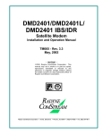
AutoEQ™ PIIC Interface Theory of Operation
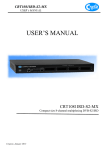
AutoEQ™ PIIC Interface allows the ability to compensate for the overall system Group Delay
and Amplitude Equalization over the satellite by pre-distorting the Uplink Carrier, eliminating the
need for external Group Delay/Amplitude Equalizers. AutoEQ™ will automatically generate the
proprietary profile for the DM240XR to pre-distort the modulator, resulting in Amplitude and
Group Delay equalization over the Satellite Link.
Figure 1. Auto EQ PIIC Card Usage
MN-DM240XR– Revision 12
D–2
DM240XR High-Speed Digital Modulator
AutoEQ™ Interface Operation Guide
AutoEQ™ supports SCPC equalization of Group Delay and Amplitude over the satellite system.
When installed into the PIIC slot of the DM240XR (with Firmware Revision FO5377-J or
higher), the AutoEQ™ Calibration menu will be displayed allowing for selection and monitoring
of the AutoEQ™ functions. The AutoEQ™ will operate over the full transponder from a symbol
rate of 10.1 Msps to 45 Msps.
Note, the 45 Msps AutoEQ™ requires a different PIIC card (PLR5972) than the original PIIC
card (PLR5808) operating to 38 Msps. The new AutoEQ™ card supersedes and replaces the
original one and both are supported by revision N or later firmware.
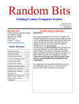
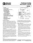
When the AutoEQ™ Calibration mode is selected, the DM240XR will disable the existing
programmed modulated outbound signal, and replace it with the AutoEQ™ calibration signal at
the same Symbol Rate, Roll off, and Transmit frequency as programmed into the DM240XR.
This signal is transmitted to the satellite, and received (Satellite Loop-Back) by the DM240XR
AutoEQ™ input at the L-Band downlink frequency. The AutoEQ™ calibration mode will
demodulate the received signal, and automatically calculate the required pre-distortion parameters
for the Satellite Link.
This information is read by the DM240XR modulator where the new pre-distort values are
programmed into the outbound carrier, resulting with the required pre-distortion of the TX output.
Upon successful completion of the calibration cycles, the DM240XR will automatically return to
the programmed outbound signal (such as DVB-S2) with the proper pre-distortion for the satellite
loop per the selected symbol rate, roll off and transponder frequency. If any parameters are
changed affecting Symbol Rate or Roll off, AutoEQ™ must be re-calibrated to the new
parameters. At any time, AutoEQ™ can be enabled or disabled.
The DM240XR is capable of retaining 32 AutoEQ™ satellite loop pre-distortion values, which
can be useful for systems requiring relocation to different transponders or Satellites. Once the
applicable transponder is calibrated, the calibration information can be stored in memory for use
now or in the future. All storage locations can be renamed by the user to correspond with the
identification of the transponder, and recalled for operational use.
Figure 2 AutoEQ™ Satellite Loopback
MN-DM240XR– Revision 12
D–3
DM240XR High-Speed Digital Modulator
D.4
AutoEQ™ Interface Operation Guide
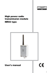
AutoEQ™ Menu Options and Parameters
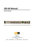
These Menu options are only available when the DM240XR is configured for AutoEQ™
operation. Refer to Figure 3 for the AutoEQ™ portion of the DM240XR Menu Tree. The
DM240XR must have software Version FO5377-J or higher to operate the AutoEQ™ PIIC
Interface Card. These Menu options are also available on the Ethernet Web browser (J6), the
RS232 (J1) terminal port, and the Remote Port (J4) of the DM240XR. Refer to the DM240XR
Manual for all Modulator related options and Parameters.
Figure 3 AutoEQ™ Menu Tree
MN-DM240XR– Revision 12
D–4
DM240XR High-Speed Digital Modulator
AutoEQ™ Interface Operation Guide
EQ ENABLE:
{Enable, Disable}
Allows the DM240XR Modulator to implement the AutoEQ™
coefficient values as specified by the EQ Select.
EQ SELECT:
{None, User Specified Name}
Allows the DM240XR Modulator to select the stored AutoEQ™
coefficient file to be implemented. Up to 32 User Nameable
storage locations are available.
RXIF:
{950 – 2050 MHz}
Sets the receive input center frequency for the AutoEQ™
Interface Card. This programmed frequency must be within + 25
kHz of the actual desired system downlink center frequency to
insure proper acquisition.
MSE:
{Value}
Displays the Mean Squared Error (MSE) value of the equalizer.
A value of 1 E-5 or less indicates a successful calibration run
with acceptable coefficients for operation over the satellite.
EQ CAL:
{Normal, Calibrating, Ref ACQ}
Allows the DM240XR Modulator to select the AutoEQ™
interface mode of operation.
Normal: When in this state, the AutoEQ™ is in monitoring
mode, with no Calibration or Reference Acquisition functions
being preformed.
Calibrating: When in this state, the AutoEQ™ will program the
DM240XR modulated output for the AutoEQ™ calibration
signal. The calibration output bandwidth is set by the symbol
rate currently programmed into the DM240XR Modulator.
During calibration, the AutoEQ™ will compute the coefficient
values required to successful equalize the group delay and
amplitude of the satellite link over the programmed symbol rate.
During this process, the MSE can be monitored reflecting the
calibration process. Upon successful completion of the
calibration, the EQ CAL will revert to the “Normal” state, and
the event log of the DM240XR will reflect “AutoEQ™ CAL
SUCCESSFUL”.
MN-DM240XR– Revision 12
D–5
DM240XR High-Speed Digital Modulator
AutoEQ™ Interface Operation Guide
(EQ CAL: Cont)
REF ACQ: Although default reference files are provided, the
operator may wish to acquire the best possible reference from
their modulator. A mechanism to accomplish this is allowed by
REF ACQ, this overwrites the stored default and replaces it with
a new reference. Prior to entering this state, the L-Band output
of the DM240XR (J11) must be connected to the AutoEQ™
RXRF Input (J12). The DM240XR Output power should be set
to -20 dBm, and a 20 dB in line attenuator should be used. The
Modulator output frequency should be set to set to the
corresponding AutoEQ™ RXRF Input Frequency. When
properly connected and in this state, the AutoEQ™ will program
the DM240XR modulated output for the AutoEQ™ calibration
signal. The calibration output bandwidth is set by the symbol
rate currently programmed into the DM240XR Modulator.
During reference calibration, the AutoEQ™ will obtain receive
lock and establish the baseline coefficients for internal reference.
References are captured for each modulator roll-off and
oversample rate. During this process, the MSE can be monitored
reflecting the Reference Acquisition process. Upon successful
completion of the Reference Acquisition, the REF ACQ will
revert to the “Normal” state, and the event log of the DM240XR
will reflect “REF ACQ SUCCESSFUL”.
RESTORE EQ CAL:
{Filename}
Allows the selected Calibration coefficient file to be Restored.
EQ RENAME:
{Filename}
Allows the Calibration coefficient file to be renamed using
Alpha-numeric characters.
EQ DELETE:
{Filename}
Allows the selected Calibration coefficient file to be deleted.
EQ RECEIVER:
{Local, Remote}
Allows selection of Local or Remote Equalization.
MN-DM240XR– Revision 12
D–6
DM240XR High-Speed Digital Modulator
D.5
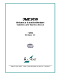
AutoEQ™ Interface Operation Guide
AutoEQ™ Back Channel Menu Options and Parameters
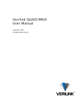
These Menu options are only available when the DM240XR is configured for AutoEQ™
operation. Refer to Figure 4 for the back channel portion of the DM240XR Menu Tree. The
DM240XR must have software Version FO5377-J or higher to operate the AutoEQ™ PIIC
Interface Card. These Menu options are also available on the Ethernet Web browser (J6), the
RS232 (J1) terminal port, and the Remote Port (J4) of the DM240XR. Refer to the DM240XR
Manual for all Modulator related options and Parameters.
Figure 4. AutoEQ™ Back Channel Menu Tree
MN-DM240XR– Revision 12
D–7
DM240XR High-Speed Digital Modulator
D.6
AutoEQ™ Interface Operation Guide
AutoEQ Backchannel Setup
Introduction
To support remote equalization with the AutoEQ system, the equalization data is
transported over TCP/IP using a backchannel protocol. Before setting up the
backchannel, perform the TCP/IP Ethernet setup as outlined in the TCP/IP Ethernet Setup
section of the user manual. This document is to be used only as a guideline for setting up
the backchannel menus. Contact the Network administrator for proper guidance and
support to ensure setup is successful.
Backchannel Configuration
Using the Front Panel display and arrow keys, scroll thru the System menu until the
Backchannel sub menu is displayed. Both the local unit (the Modulator) and the remote
unit (with the AutoEQ card installed) require the proper configuration with the correct
network settings.
Refer to Figure 4.
Note: The router/gateway/firewall system must be configured to allow these ports to
pass on each communication end. Contact your Network Administrator for allowable
port numbers and to open up the ports on the firewall if necessary.
Enter into the Backchannel menu and the following sub menus will appear, however the
order may vary.
LOCAL PORT:
{XXXX}
The local port number must be set to the same value at
both the local and remote sites.
SERVER PORT:
{XXXX}
The server port number must be set to the same value at
both the local and remote sites.
Note: The local port and server port values must be different from the local and remote
sites.
SERVER IP ADDR:
{XXX.XXX.XXX.XXX} Hexidecimal Address
{ddd.ddd.ddd.ddd} Decimal Address
On the local unit, this should have the value of the
remote unit’s IP address.
Note: If the remote IP address is not publicly accessible then its translated NAT
(Network Address Translation) needs to be applied.
RECEIVE TIMEOUT:
{X.X MINUTES}
This value is factory set, and should only be adjusted as directed by your Network
administrator or Radyne Customer Service.
REPLY TIMEOUT:
{XX secs}
This value is factory set, and should only be adjusted as directed by your Network
administrator or Radyne Customer Service.
MN-DM240XR– Revision 12
D–8
DM240XR High-Speed Digital Modulator
AutoEQ™ Interface Operation Guide
Figure 5. AutoEQ™ Backchannel Setup
Back Channel Test
The "BACK CHAN TEST" does the following:
1. Establishes a connection with the back channel server as defined under the
SYSTEM->BACK CHANNEL menu.
2. Issues a ping to the back channel server.
3. Sends a message to and validates the reply from the back channel server application
running on the back channel server.
4. If passes, no additional; events will appear in the event log.
5. If fails, logs one of the following events on the local side event log:
a. "BACK CHANNEL TEST: FAILED PING"
b. "BACK CHANNEL TEST: FAILED BACK CHAN SERVICE REQ"
c. "BACK CHANNEL TEST: REPLY FORMAT ERROR"
d. "BACK CHANNEL TEST: ERROR REPLY"
6. If fails, may log one of the following events on the server side event log:
a. "INVALID CHANNEL TEST SIZE"
b. "INVALID CHANNEL TEST PAYLOAD"
Ethernet Test
Verify Local Router:
On the local unit, using the Front Panel display and arrow keys, scroll thru the Monitor
menu and clear the Event Log.
Now scroll thru the Test menu and Ping Test the TCP/IP ROUTER. If the event LED on
the front panel does not light, communications between the modem and its router was
successful.
Verify Remote Router:
Perform the same test on the remote unit as detailed under Verify Local Router.
Verify Local to Remote Connection:
On the local unit, using the Front Panel display and arrow keys, scroll thru the Monitor
menu and clear the Event Log.
Now scroll thru the Test menu and Ping Test the BK CHAN SERVER. If the event LED
on the front panel does not light, communications between the local modem and the
remote modem was successful.
MN-DM240XR– Revision 12
D–9
DM240XR High-Speed Digital Modulator
D.7
AutoEQ™ Interface Operation Guide
AutoEQ™ Operation Procedure
The following sequence must be followed in order to perform the initial AutoEQ™ Calibration.
The sequence is identified into three (3) individual sections: 1) Reference Acquisition
Calibration (REF ACQ) - optional, 2) Equalizer Calibration (CALIBRATING), and 3) Equalizer
Modes (NORMAL). These three menu selections are selectable under EQ CAL.
All DM240XR Faults and Alarms must be cleared prior to any AutoEQ™
Calibration process. If Data is not present on the DM240XR Data interface
causing a data Alarm, Advanced ASI may be selected for the AutoEQ™
Calibration (Advanced ASI inserts Null Packets into the Data Stream).
D.8
Reference Acquisition Calibration (Optional Step)
This Section will establish the calibration reference for the AutoEQ™ Interface Card. This
optional step may be preformed prior to Equalizer Calibration. This step is optional as
default reference(s) are already loaded into the system. This operation will replace the
default reference(s) with the actual references measured during the calibration cycle. The
modulator must be programmed for an L-Band frequency and the AutoEQ™ RXIF
Frequency programmed to match.
1. Install the AutoEQ™ PIIC Interface into one of the available PIIC Slots on the DM240XR.
2. Verify that the DM240XR revision is FO5377-K or greater.
3. Insure that there is a Flash Card installed in the Flash Card slot on the DM240XR.
4. Using the Front Panel menu, set the DM240XR Modulator Data Rate, Modulation type, Roll
off, and remaining Modulator parameters to the required system settings.
5. Using the Front Panel menu, scroll to “RXIF” located under the EQUALIZER menu and set
the AutoEQ “RXIF”.
For best results it is suggested that the RXIF frequency used to acquire the
reference be the actual frequency used to perform the equalization calibration.
6. Using the Front Panel menu, set the DM240XR Transmit Frequency (L-Band) to match the
programmed AutoEQ RXIF Frequency.
7. Using the Front Panel menu, set the DM240XR TX Output Power to -10 dBm.
8. Connect the DM240XR L-BAND Output (J11) through a 20 dB attenuator then to the AutoEQ
Interface RXRF Input (J12) using a suitable L-Band Cable.
MN-DM240XR– Revision 12
D–10
DM240XR High-Speed Digital Modulator
AutoEQ™ Interface Operation Guide
Figure 6. AutoEQ™ Ref Acq Set-up
For best results place the attenuator pad as close to the AutoEQ port (J12) as
possible.
9. Clear the events of the modulator by scrolling to <MONITOR> then down and over to <PRESS
CLEAR TO ERASE EVENTS> and press clear. Verify that the Event LED is now off.
10. Using the Front Panel menu, scroll to “EQ CALIBRATION” and set to “REF ACQ”
a. After a successful calibration the event log will display “REF ACQ SUCCESSFUL” upon
completion of this step. When the REF ACQ is complete, the “EQ CALIBRATION” will
revert to “NORMAL”.
11. Remove the interconnect cable installed in Step 8 above.
12. Verify through the event log that the system successfully calibrated the reference.
D.9
Equalizer Calibration
For best AutoEQ equalization calibration it is recommended that the amplifier be
run in its linear range and not saturated.
The AutoEQ™ RXRF Acquisition range is + 25 kHz from the programmed frequency and is not
programmable. To insure proper operation, the actual center frequency of the carrier should be
accurately measured with this measured value programmed into the AutoEQ™. This can be
accomplished by generation a CW (Carrier Wave) frequency with the modulator, and measuring
the downlink L-Band frequency with an accurate frequency counter or spectrum analyzer.
1. Reprogram the DM240XR Modulator output frequency to the proper operating frequency of
the Uplink system (if it was reprogrammed for Section 4.1 above) and the output power to the
system operating level. Connect the DM240XR Modulator output to the Uplink system.
Enable the modulator and adjust all uplink parameters as required for proper uplink
operation.
2. Measure the center frequency of the down converted modulated signal. Using the front panel
Menu, reprogram the AutoEQ™ to the center frequency of the down converted signal. The
AutoEQ™ programmed frequency must be within + 25 kHz of the measured frequency in
MN-DM240XR– Revision 12
D–11
DM240XR High-Speed Digital Modulator
AutoEQ™ Interface Operation Guide
order to assure proper acquisition of the downlink signal. Connect the AutoEQ™ Input (J12)
to the earth Station L-Band Downlink System. The desired downlink carrier should be
typically between the range of -45 to -20 dBm.
3. Clear the events of the modulator by scrolling to <MONITOR> then down and over to
<PRESS CLEAR TO ERASE EVENTS> and press clear. Verify that the Event LED is now
off.
4. Using the Front Panel menu, scroll to “EQ CAL” and set it to “CALIBRATING”. This will
start the AutoEQ™ Calibration for the Satellite Link.
a. After each data acquisition and processing cycle the MSE display will be updated. A normal
calibration cycle will take 60 to 90 seconds, and system typically performs two or three of
these cycles.
b. During this calibration, the MSE can be monitored showing the progress of the cycle. A
value of 1 E-5 or less will reflect a success full completion of this step. Additionally, event
light will come on, and the event log will display “EQ CAL SUCCESSFUL” upon
completion of this step. When the EQ CAL is complete, the “EQ CAL” will revert to
“NORMAL” and the AutoEQ file will be named “UNTITLED”.
The AutoEQ calibration must be saved or powering down of the system will lose
the calibration.
5. To change the name of the “UNTITLED” file, using the Front Panel menu, scroll to EQ
RENAME, Press ENTER, use the Up/DN Arrows on the Keyboard to change the name, and press
ENTER to save the new name for the file.
6. Using the Front Panel menu, scroll to “SAVE EQ CAL”, and press ENTER to save the file.
D.10 Equalizer Modes
The AutoEQ feature must be enabled on the DM240XR, and section 4.2 Equalizer Calibration
must be performed prior to this section.
Disable Mode
MN-DM240XR– Revision 12
D–12
DM240XR High-Speed Digital Modulator
AutoEQ™ Interface Operation Guide
To disable a programmed Equalizer Setting, use the Front Panel and scroll to “EQUALIZER”,
press the Enter” key, change the selection to “DISABLE”, and press the Enter key. This will
disable the Equalizer, and allow for normal operation of the DM240XR.
Enable Mode
To enable the equalizer, use the front panel and scroll to “EQ SELECT” and press the Enter key.
Using the Up/Dn keys, scroll to the desired saved equalizer file, and press the Enter key to select
the file. Scroll back to Equalizer, press the Enter key, and using the Up/Dn keys, scroll to
“ENABLE” and press the Enter key. This will enter the selected equalizer file parameters into
the DM240XR Modulator and initiate AutoEQ™ equalization.
D.11 AutoEQ™ Remote Operation
To operate the AutoEQ™ system in remote, perform the following setup steps.
1. The TCP/IP Ethernet Setup described in the operator manual
2. The Backchannel Setup as described in Section 4.0
3. Select REMOTE under the EQ RECEIVER Submenu
4. Perform the Operations as described in Section 5.0 for equalization
Figure 7. Remote AutoEQ™ Site Equalization
MN-DM240XR– Revision 12
D–13
DM240XR High-Speed Digital Modulator
AutoEQ™ Interface Operation Guide
D.12 Additional Features
D.12.1
AutoEQ™ Status Indicator
The LED on the back of the AutoEQ™ interface card can provide additional status for the
operation of the AutoEQ™ system.
D.12.2
Short Blink Green
Heartbeat, board ready for operation.
Solid Green
AutoEQ™ test pattern lock.
Solid Yellow
AutoEQ™ data being accessed.
Blink Red
AutoEQ™ test pattern unlocked. Signal error.
LNB Power Connector
On the back of the AutoEQ™ interface card is the connector J13 that can be used to insert LNB
power to the J12 SMA connector to feed DC to the LNB.
Mating Connector: PP3-002A 5.5mm x 2.1mm x 9.5mm In-Line DC Power Plug.
(www.cui.com)
MN-DM240XR– Revision 12
D–14
Errata B
Comtech EF Data Documentation Update
Subject:
Date :
Original Manual
Part Number/Rev:
Errata Number/
PLM Document
ID:
PLM CO Number:
Comments:
Revise Chapter 7. Technical Specifications – Update DM240XR IF Frequency
Specification
Per PLM System
MN-DM240XR Rev 12
ER-DM240XR-EB12
C-0023872
The information provided in this erratum will be incorporated into the next
formal revision of the manual.
Revise Sect. 7.2 IF Specification / Frequency Stability (page 7-1):
ER-DM240XR-EB12
THIS DOCUMENT IS NOT SUBJECT TO REVISION/UPDATE! PLM CO C-0023872
Page 1 of 2
Errata C for MN-DM240XR Rev 12
Errata C
Comtech EF Data Documentation Update
Subject:
Revise Chapter 9. Remote Operations – Add Auto EQ data
Date : Per PLM System
Original Manual
Part Number/Rev: MN-DM240XR Rev 12
Errata Number/
PLM Document
ID:
PLM CO Number:
Comments:
ER-DM240XR-EC12
C-0024011
The information provided in this erratum will be incorporated into the next
formal revision of the manual.
See attached pages for Chapter 9.
ER-DM240XR-EC12
Errata C for MN-DM240XR Rev 12
Blank Page
ER-DM240XR-EC12
DM240XR High-Speed Digital Modulator
Remote Operations
Source
<1>
Reserved
TBD, Default = 0
<11>
Reserved
TBD
<1>
Reserved
TBD
<1>
Major Alarm
Mask
Bit 0 = Spare
Bit 1 = Transmit Oversample PLL Lock
Bit 2 = FPGA Config Error
Bit 3 = IF Synthesizer PLL Lock
Bit 4 = External Reference PLL Lock
Bit 5 = Composite (SCT) PLL Lock
Bit 6 = Symbol PLL Lock
Bit 7 = Spare
0 = Mask, 1 = Allow
<1>
Minor Alarm
Mask
Bit 0 = Terrestrial Ethernet data activity detect
Bit 1 = Loss Terrestrial Clock
Bit 2 = Loss Terrestrial Data
Bit 3 = FIFO Error
Bit 4 = Output Level
Bit 5 = Terrestrial Framing Error
Bit 6 = Terr Ethernet jitter buffer underflow
Bit 7 = Terr Ethernet jitter buffer overflow
0 = Mask, 1 = Allow
<1>
Common Fault
Mask
<1>
Reserved
<4>
Symbol Rate
<1>
Terrestrial
Framing
<1>
Roll Off
0 = 0.35, 25 = 0.25, 1 = 0.20
<1>
Reserved
TBD
Bit 0 = -12 V Alarm
Bit 1 = +12 V Alarm
Bit 2 = +5 V Alarm
Bit 3 = Spare
Bit 4 = Spare
Bit 5 = Spare
Bit 6 = Spare
Bit 7 = Spare
0 = Mask, 1 = Allow
TBD, Default = 0
Symbol Rate in Symbols Per Second
0 = 188 Byte, 1 = 204 Byte, 2 = No Framing
5 = COP3, 6 = ACM, 7 = Bridge
<1>
Output Clock CTE, 1 = SCT, 2 = None
Source
<1>
Network Spec
MN-DM240XR– Revision 12
0 = DVB-S
9 = DirecTV
11 = DVB-S2 CCM
13 = Only DirecTV
15 = DVB-S2 ACM
9–5
DM240XR High-Speed Digital Modulator
Remote Operations
<1>
BB Scrambler
Bypass
0 = Normal, 1 = Bypass
<1>
Outer FEC
Bypass
0 = Normal, 1 = Bypass
<1>
Test Pattern
0 = None, 1 = 215 – 1, 23 = 223-1
<1>
Last Rate
Control
0 = Symbol Rate, 1 = Data Rate, 2 = Auto
<1>
Interleaver
Bypass
0 = Bypass, 1 = Normal
<1>
PCR
Restamping
0 = Off, 1= On
<1>
Multi-PIIC
Mode
1 = Manual,
2 = Redundancy
<1>
Redundancy
Mode
0 = Force Prime,
1 = Force Backup,
2 = Manual Revert,
3 = Auto-Revert
<1>
Prime PIIC Slot
1–3
<1>
Backup PIIC
Slot
1–3
<1>
Pilot Symbols
0 = Off, 1= On
<1>
Inner FEC
Bypass
0 = Normal, 1 = Bypass
<1>
PL Scrambler
Bypass
0 = Normal, 1 = Bypass
<1>
Reserved
Set to 0
<1>
Reserved
Set to 1
<2>
Reserved
Set to 0
<4>
Gold Code Seq
Index
<1>
Sat Framing
<1>
Auto EQ
Enable
<9>
Auto EQ Filter
Coef Name
0 to 262142
3=DVB-S, 5=DTV, 10=DVB-S2 Normal, 15=DVB-S2 Short
0=Off, 1=On
8-character NULL terminated string, this is the filter’s name
as shown on the front panel (identical to the filter’s base
filename, the extension is assumed to be “AEQ”)
Status Bytes
<1>
Reserved
<1>
Reserved
MN-DM240XR– Revision 12
9–6
DM240XR High-Speed Digital Modulator
Remote Operations
<1>
Redundancy
Mode
0 = Force Prime,
1 = Force Backup,
2 = Manual Revert,
3 = Auto-Revert
<1>
Prime PIIC Slot
1–3
<1>
Backup PIIC
Slot
1–3
<1>
Pilot Symbols
0 = Off, 1= On
<1>
Inner FEC
Bypass
0 = Normal, 1 = Bypass
<1>
PL Scrambler
Bypass
0 = Normal, 1 = Bypass
<1>
Reserved
Set to 0
<1>
Reserved
Set to 1
<2>
Reserved
Set to 0
<4>
Gold Code Seq
Index
<1>
Sat Framing
<1>
Auto EQ
Enable
<9>
Auto EQ Filter
Coef Name
0 to 262142
3=DVB-S, 5=DTV, 10=DVB-S2 Normal, 15=DVB-S2 Short
0=Off, 1=On
8-character NULL terminated string, this is the filter’s name
as shown on the front panel (identical to the filter’s base
filename, the extension is assumed to be “AEQ”)
DM240XR Clock Source Selection Matrix
Interface Type
InClk Source
OutClk Source
RS-422 Serial
SCT or SCTE
SCT Only
G.703 (E3, T3, STS-1)
SCTE Only
SCT, SCTE, or None
HSSI
SCT or SCTE
SCT Only
OC3
SCTE Only
None
STM-1
SCTE Only
None
ASI, Advanced ASI
SCTE Only
None
M2P Parallel
SCT or SCTE
SCT Only
DVB Parallel
SCTE Only
SCT Only
MN-DM240XR– Revision 12
9–19
DM240XR High-Speed Digital Modulator
Remote Operations
When changing Data Rate, Symbol Rate, Inner FEC Rate, Modulation Type,
or Terrestrial Framing using the Mod All Command, the Data Rate and
Symbol Rate parameter must be range checked using the following formulas
to ensure they do not exceed the max limits:
Symbol Rate = (Data Rate * Overhead)/(Code Rate * Modulation)
Data Rate = (Symbol Rate * Code Rate * Modulation)/Overhead
Maximum Symbol Rate
68 Msps.
Maximum Data Rate
238 Mbps with high-speed interface card.
Overhead
204/188 for 188 byte
204/204 for 204 byte
204/187 for none
Modulation
QPSK = 2, 16QAM = 4,
Code Rate
1/4, 1/3, 2/5, 3/5, 1/2, 2/3, 3/4, 5/6, 6/7, 7/8, 8/9, 9/10
MN-DM240XR– Revision 12
BPSK = 1, 8PSK = 3
9–20
Errata B for MN-DM240XR Rev 12
Revise DM240XR IF Frequency Stability Specification
This page is intentionally blank.
ER-DM240XR-EB12
THIS DOCUMENT IS NOT SUBJECT TO REVISION/UPDATE! PLM CO C-0023872
Page 2 of 2
Table of Contents
TABLE OF CONTENTS .............................................................................................................. III
CHAPTER 1.
1.1
INTRODUCTION ................................................................................... 1–1
Description ................................................................................................................................... 1–1
CHAPTER 2.
INSTALLATION .................................................................................... 2–1
2.1
Installation Requirements .......................................................................................................... 2–1
2.2
Unpacking .................................................................................................................................... 2–2
2.3
Removal and Assembly............................................................................................................... 2–2
2.4
Mounting Considerations ........................................................................................................... 2–2
2.5
Modulator Checkout ................................................................................................................... 2–3
2.5.1
Initial Power-Up.................................................................................................................... 2–3
CHAPTER 3.
THEORY OF OPERATION ................................................................... 3–1
3.1
Theory of Operation ................................................................................................................... 3–1
3.2
DVB-S Operation ........................................................................................................................ 3–1
3.3
DVB-S2-BS-NBC Operation ...................................................................................................... 3–2
CHAPTER 4.
4.1
USER INTERFACES ............................................................................. 4–1
User Interfaces ............................................................................................................................ 4–1
4.2
Front Panel User Interface ......................................................................................................... 4–1
4.2.1
Front Panel LCD Display ...................................................................................................... 4–2
4.2.2
Front Panel LED Indicators .................................................................................................. 4–2
4.2.3
Front Panel Keypad............................................................................................................... 4–2
4.2.4
Parameter Setup .................................................................................................................... 4–3
4.3
Front Panel Control Screen Menus ........................................................................................... 4–5
4.3.1
Main Menus .......................................................................................................................... 4–5
4.3.2
Modulator Menu Options and Parameters ............................................................................ 4–6
4.3.3
Interface Menu Options and Parameters ............................................................................... 4–9
4.3.3.1 Plug-In Interface Card (PIIC) ......................................................................................... 4–10
4.3.3.2 Ethernet Interface (J1) ..................................................................................................... 4–12
4.3.4
RF Switch Menu Options and Parameters .......................................................................... 4–20
4.3.5
Monitor Menu Options and Parameters .............................................................................. 4–20
4.3.6
Alarms Menu Options and Parameters ............................................................................... 4–20
iii
Table of Contents
DM240XR High-Speed Digital Modulator
4.3.7
4.3.8
Revision 12
MN-DM240XR
System Menu Options and Parameters ............................................................................... 4–22
Test Menu Options and Parameters .................................................................................... 4–30
4.4
Remote Port User Interface ..................................................................................................... 4–30
4.4.1
Protocol Structure ............................................................................................................... 4–31
4.4.2
Protocol Wrapper ................................................................................................................ 4–31
4.4.3
Frame Description and Bus Handshaking ........................................................................... 4–34
4.4.4
Global Response Operational Codes................................................................................... 4–34
4.4.5
Collision Avoidance............................................................................................................ 4–36
4.4.6
Software Compatibility ....................................................................................................... 4–37
4.4.7
RLLP Summary .................................................................................................................. 4–38
4.4.8
DM240XR Opcode Command Set ..................................................................................... 4–38
4.5
Ethernet Port User Interface ................................................................................................... 4–39
4.6
Simple Network Management Protocol (SNMP) ................................................................... 4–39
4.7
The Management Information Base (MIB) ............................................................................ 4–39
4.7.1
Directory {internet 1} 1.3.6.1.1 ........................................................................................ 4–39
4.7.2
Mgmt {internet 2} 1.3.6.1.2 ............................................................................................. 4–39
4.7.3
Experimental {internet 3} 1.3.6.1.3 ................................................................................... 4–39
4.7.4
Private {internet 4} 1.3.6.1.4 ............................................................................................ 4–40
4.8
Terminal Port User Interface................................................................................................... 4–41
4.8.1
Connecting the Terminal ..................................................................................................... 4–42
4.8.2
Terminal Screens ................................................................................................................ 4–42
CHAPTER 5.
REAR PANEL INTERFACES ............................................................... 5–1
5.1
DM240XR Connections .............................................................................................................. 5–1
5.2
AC Power ..................................................................................................................................... 5–3
5.3
Compact Flash Interface (J5)..................................................................................................... 5–3
5.3.1
Feature Upgrade .................................................................................................................... 5–3
5.3.2
Firmware Update .................................................................................................................. 5–3
5.3.3
Custom Configuration ........................................................................................................... 5–4
5.4
Ethernet Interface (J6) ............................................................................................................... 5–4
5.5
External Reference (Input) ........................................................................................................ 5–4
5.6
Remote Port (I/O) ....................................................................................................................... 5–4
5.7
Terminal Port (I/O)..................................................................................................................... 5–5
5.8
Alarm Port ................................................................................................................................... 5–5
5.9
IF Output Port (J10 & J11) ........................................................................................................ 5–6
5.9.1
Output Monitor Port (J9)....................................................................................................... 5–6
iv
Table of Contents
DM240XR High-Speed Digital Modulator
Revision 12
MN-DM240XR
5.10
RF Redundancy Switch Control (J2) ........................................................................................ 5–6
5.11
Built in ASI/Advanced ASI Interface (J7) ................................................................................ 5–6
5.12 Plug-In Interface Cards (PIICs) ................................................................................................ 5–7
5.12.1
ASI PIIC................................................................................................................................ 5–7
5.12.1.1 ASI (Asynchronous Serial Interface) ................................................................................ 5–7
5.12.1.2 AASI (Advanced Asynchronous Serial Interface) ............................................................ 5–7
5.12.2
ASI Monitor .......................................................................................................................... 5–8
5.12.3
Parallel RS-422 Interface ...................................................................................................... 5–8
5.12.3.1 M2P (Parallel, RS-422) ..................................................................................................... 5–8
5.12.3.2 DVB (Parallel, RS-422) .................................................................................................... 5–9
5.12.4
Parallel LVDS Interface ...................................................................................................... 5–10
5.12.5
HSSI Interface ..................................................................................................................... 5–10
5.12.6
Ethernet 100/1000 Base-T Interface ................................................................................... 5–11
5.12.7
EIA-530 /RS-422 Serial Interface ....................................................................................... 5–11
5.12.8
G.703 Interface (Contact factory for availability)............................................................... 5–12
CHAPTER 6.
6.1
MAINTENANCE AND TROUBLESHOOTING ...................................... 6–1
Periodic Maintenance ................................................................................................................. 6–1
CHAPTER 7.
TECHNICAL SPECIFICATIONS ........................................................... 7–1
7.1
Introduction ................................................................................................................................. 7–1
7.2
IF Specification............................................................................................................................ 7–1
7.3
Baseband Specification ............................................................................................................... 7–2
7.3.1
DVB-S................................................................................................................................... 7–2
7.3.2
DVB-S2-CCM (CCM - Normative) .................................................................................... 7–2
7.3.3
DVB-S2-ACM (Normative Features with Single Transports streams) ................................ 7–3
7.4
Interface Types Available (PIIC)............................................................................................... 7–4
7.5
Monitor and Control................................................................................................................... 7–4
7.6
Environmental ............................................................................................................................. 7–4
7.7
Physical ........................................................................................................................................ 7–5
7.8
Options ......................................................................................................................................... 7–5
7.9
DVB-S Series Configuration ...................................................................................................... 7–5
7.9.1
DVB-S2 Series Configuration .............................................................................................. 7–5
7.10 Data Rates (DVB-S) .................................................................................................................... 7–5
7.10.1
Data Rates (DVB-S2)............................................................................................................ 7–7
CHAPTER 8.
SNMP .................................................................................................... 8–1
v
Table of Contents
DM240XR High-Speed Digital Modulator
CHAPTER 9.
Revision 12
MN-DM240XR
REMOTE OPERATIONS....................................................................... 9–1
9.1
DM240XR Opcode Command Set ............................................................................................ 9–1
9.2
Modulator Command Set ........................................................................................................... 9–1
9.3
Detailed Command Descriptions ............................................................................................... 9–3
CHAPTER 10.
10.1
WEB BROWSER................................................................................. 10–1
Web Browser User Interface .................................................................................................... 10–1
10.2 Configuring Your PC ............................................................................................................... 10–2
10.2.1
LED Indicators .................................................................................................................... 10–3
10.3 GUI Screen Menus .................................................................................................................... 10–4
10.3.1
Introduction Menu .............................................................................................................. 10–5
10.3.1.1 Login Screen ................................................................................................................... 10–6
10.3.2
Password Setup ................................................................................................................... 10–7
10.3.3
IP and Application Administration ..................................................................................... 10–9
10.3.4
Monitor and Control Menu ............................................................................................... 10–14
10.3.4.1 Transmit Menu .............................................................................................................. 10–14
10.3.4.2 Interface Menu .............................................................................................................. 10–16
10.3.4.3 RFSWITCH Menu ........................................................................................................ 10–17
10.3.4.4 Monitor Menu ............................................................................................................... 10–17
10.3.4.5 Alarms Menu ................................................................................................................ 10–19
10.3.4.6 System Menu ................................................................................................................ 10–20
10.3.4.7 Test Menu ..................................................................................................................... 10–22
APPENDIX A.
FRONT PANEL UPGRADE PROCEDURE ......................................... A–1
A.1
Introduction ................................................................................................................................ A–1
A.2
Required Equipment ................................................................................................................. A–1
A.3
Upgrade Procedure .................................................................................................................... A–1
A.4
Demonstration Procedure ......................................................................................................... A–3
A.4.1
Running in Demonstration Mode ......................................................................................... A–5
A.4.2
Canceling Demonstration Mode .......................................................................................... A–6
APPENDIX B.
TCP/IP ETHERNET SETUP ................................................................. B–1
B.1
Introduction ................................................................................................................................ B–1
B.2
TCP/IP Network Configuration ............................................................................................... B–1
B.3
Network Configuration Summary ............................................................................................ B–3
B.4
Ethernet Test .............................................................................................................................. B–3
vi
Table of Contents
DM240XR High-Speed Digital Modulator
B.4.1
B.4.2
B.4.3
Connecting the Modem Ethernet Cable to a Network Link ................................................. B–3
Connecting the Modem Ethernet Cable Directly to a Computer (without a Network) ........ B–4
Testing the Ethernet connection using the Ping Program (Optional)................................... B–6
APPENDIX C.
C.1
Revision 12
MN-DM240XR
WEB BROWSER QUICK SETUP GUIDE............................................ C–1
Introduction ................................................................................................................................ C–1
C.2
Web Users Configuration .......................................................................................................... C–2
C.2.1
Change Web User Name ...................................................................................................... C–3
C.2.2
Change Authentication Password ........................................................................................ C–3
C.2.3
Change Access Rights.......................................................................................................... C–4
C.3
Modem Web Site ........................................................................................................................ C–4
C.4
Web Page Appearance ............................................................................................................... C–5
APPENDIX D.
AUTOEQ™ INTERFACE OPERATION GUIDE .................................. D–1
D.1
Introduction ................................................................................................................................ D–1
D.2
Applicable Documents ............................................................................................................... D–1
D.3
AutoEQ™ PIIC Interface Theory of Operation ..................................................................... D–1
D.4
AutoEQ™ Menu Options and Parameters ............................................................................... D–3
D.5
AutoEQ™ Back Channel Menu Options and Parameters ...................................................... D–6
D.6
AutoEQ Backchannel Setup ...................................................................................................... D–7
D.7
AutoEQ™ Operation Procedure .............................................................................................. D–9
D.8
Reference Acquisition Calibration (Optional Step) ................................................................ D–9
D.9
Equalizer Calibration .............................................................................................................. D–11
D.10
Equalizer Modes....................................................................................................................... D–12
D.11
AutoEQ™ Remote Operation ................................................................................................. D–13
D.12 Additional Features ................................................................................................................. D–14
D.12.1 AutoEQ™ Status Indicator ................................................................................................ D–14
D.12.2 LNB Power Connector ....................................................................................................... D–14
vii
Table of Contents
DM240XR High-Speed Digital Modulator
Revision 12
MN-DM240XR
Notes:
viii
PREFACE
About this Manual
This manual describes the installation and operation for the Radyne DM240XR. This is a
technical document intended for earth station engineers, technicians, and operators responsible
for the operation and maintenance of the DM204XR.
Reporting Comments or Suggestions Concerning this Manual
Comments and suggestions regarding the content and design of this manual are appreciated. To
submit comments, please contact the Comtech EF Data Technical Publications department:
[email protected]
Conventions and References
Related Documents
The following documents are referenced in this manual:
• EN300-421 and EN301-210 ETSI
• ETSI EN302-307
• INTELSAT Earth Station Standards IESS-308, -309, -310, and -315
• EUTELSAT SMS
Metric Conversion
Metric conversion information is located on the inside back cover of this manual. This information is
provided to assist the operator in cross-referencing non-Metric to Metric conversions.
Cautions and Warnings
i
DM240XR
Preface
Revision 12
MN-DM240XR
IMPORTANT or NOTE indicates a statement associated with the task
being performed or information critical for proper equipment function.
IMPORTANT
CAUTION
CAUTION indicates a hazardous situation that, if not avoided, may result in
minor or moderate injury. CAUTION may also be used to indicate other
unsafe practices or risks of property damage.
WARNING indicates a potentially hazardous situation that, if not avoided,
could result in death or serious injury.
WARNING
Examples of
Multi-Hazard Formats
Trademarks
Product names mentioned in this manual may be trademarks or registered trademarks of their
respective companies and are hereby acknowledged.
ii
DM240XR
Preface
Revision 12
MN-DM240XR
Safety Compliance
EN 60950
Applicable testing is routinely performed as a condition of manufacturing on all units to ensure
compliance with safety requirements of EN60950.This equipment meets the Safety of Information
Technology Equipment specification as defined in EN60950.
Low Voltage Directive (LVD)
The following information is applicable for the European Low Voltage Directive (EN60950):
<HAR>
!
Type of power cord required for use in the European Community.
CAUTION: Double-pole/Neutral Fusing
ACHTUNG: Zweipolige bzw. Neutralleiter-Sicherung
International Symbols:
Symbol
Definition
~
Alternating Current
Protective Earth /
Safety Ground
Fuse
Chassis Ground
NOTE
Symbol
Definition
For additional symbols, refer to Cautions and Warnings, listed
earlier in this Preface.
iii
DM240XR
Preface
Revision 12
MN-DM240XR
Warranty Policy
Comtech EF Data products are warranted against defects in material and
workmanship for a period of two years from the date of shipment. During the
warranty period, Comtech EF Data will, at its option, repair or replace products
that prove to be defective. Repairs are warranted for the remainder of the original
two year warranty, or a 90 day extended warranty, whichever is longer.
For equipment under warranty, the owner is responsible for freight to Comtech EF
Data and all related customs, taxes, tariffs, insurance, etc. Comtech EF Data is
responsible for the freight charges only for return of the equipment from the factory
to the owner. Comtech EF Data will return the equipment by the same method
(i.e., Air, Express, Surface) as the equipment was sent to Comtech EF Data.
All equipment returned for warranty repair must have a valid RMA number issued
prior to return and be marked clearly on the return packaging. Comtech EF Data
strongly recommends all equipment be returned in its original packaging.
Comtech EF Data Corporation’s obligations under this warranty are limited to
repair or replacement of failed parts, and the return shipment to the buyer of the
repaired or replaced parts.
Limitations of Warranty
The warranty does not apply to any part of a product that has been installed,
altered, repaired, or misused in any way that, in the opinion of Comtech EF Data
Corporation, would affect the reliability or detracts from the performance of any
part of the product, or is damaged as the result of use in a way or with equipment
that had not been previously approved by Comtech EF Data Corporation.
The warranty does not apply to any product or parts thereof where the serial number
or the serial number of any of its parts has been altered, defaced, or removed.
The warranty does not cover damage or loss incurred in transportation of the
product.
The warranty does not cover replacement or repair necessitated by loss or
damage from any cause beyond the control of Comtech EF Data Corporation,
such as lightning or other natural and weather related events or wartime
environments.
The warranty does not cover any labor involved in the removal and or
reinstallation of warranted equipment or parts on site, or any labor required to
diagnose the necessity for repair or replacement.
iv
DM240XR
Preface
Revision 12
MN-DM240XR
The warranty excludes any responsibility by Comtech EF Data Corporation for
incidental or consequential damages arising from the use of the equipment or
products, or for any inability to use them either separate from or in combination with
any other equipment or products.
A fixed charge established for each product will be imposed for all equipment
returned for warranty repair where Comtech EF Data Corporation cannot identify
the cause of the reported failure.
Exclusive Remedies
Comtech EF Data Corporation’s warranty, as stated is in lieu of all other
warranties, expressed, implied, or statutory, including those of merchantability
and fitness for a particular purpose. The buyer shall pass on to any purchaser,
lessee, or other user of Comtech EF Data Corporation’s products, the
aforementioned warranty, and shall indemnify and hold harmless Comtech EF
Data Corporation from any claims or liability of such purchaser, lessee, or user
based upon allegations that the buyer, its agents, or employees have made
additional warranties or representations as to product preference or use.
The remedies provided herein are the buyer’s sole and exclusive remedies.
Comtech EF Data shall not be liable for any direct, indirect, special, incidental, or
consequential damages, whether based on contract, tort, or any other legal
theory.
v
DM240XR
Preface
Revision 12
MN-DM240XR
Customer Support
Contact the Comtech EF Data Customer Support Department for:
•
Product support or training
•
Reporting comments or suggestions concerning manuals
•
Information on upgrading or returning a product
A Customer Support representative may be reached at:
Comtech EF Data
Attention: Customer Support Department
2114 West 7th Street
Tempe, Arizona 85281 USA
480.333.2200 (Main Comtech EF Data number)
480.333.4357 (Customer Support Desk)
480.333.2161 FAX
To return a Comtech EF Data product (in-warranty and out-of-warranty) for repair or replacement:
•
Contact the Comtech EF Data Customer Support Department. Be prepared to supply
the Customer Support representative with the model number, serial number, and a
description of the problem.
•
Request a Return Material Authorization (RMA) number from the Comtech EF Data
Customer Support representative.
•
Pack the product in its original shipping carton/packaging to ensure that the product is
not damaged during shipping.
•
Ship the product back to Comtech EF Data. (Shipping charges should be prepaid.)
Online Customer Support
An RMA number request can be requested electronically by contacting the Customer Support
Department through the online support page at www.comtechefdata.com/support.asp:
•
Click on the “Service” hyperlink, then read the “Return Material Authorization” section
for detailed instructions on our return procedures.
•
Click on the “RMA Request Form” hyperlink, then fill out the form completely before
sending.
•
Send e-mail to the Customer Support Department at [email protected].
For information regarding this product’s warranty policy, refer to the Warranty Policy, p. xxii.
vi
Chapter 1. INTRODUCTION
This chapter provides an overview of the DM240XR High-Speed Digital Modulator. The
DM240XR will be referred to in this manual as “the DM240XR”, “the modulator”, or “the unit”.
1.1
Description
The New Standard in Digital Modulator Performance
Radyne’s DM240XR family of High-Speed Modulators is the ideal choice to meet the exacting
standards of High Data-Rate Video, Internet and Fiber Restoral Satellite Applications. The
DM240XR offers various options that comply to the international standards, supporting both
DVB-S and DVB-S2 specifications. With a variety of frequency options and Plug-In Data
Interfaces (PIIC), it provides greater flexibility for changing and upgrading the unit the required
application.
The DVB-S Network specification complies with both EN300-421 and EN301-210 ETSI
specifications. The DM240XR supports FEC rates of BPSK, QPSK, 8PSK and 16QAM
applications with symbol rates up to 68 Msps.
The DVB-S2 Network specification complies with the next generation DVB open standard
supported by ETSI EN302-307. At the core of this standard is a powerful Bose-ChaudhuriHocquenghem BCH encoder and concatenated Low-Density Parity Check (LDPC). The DVB-S2
FEC rates supported are BPSK, QPSK, 8PSK and 16APSK with symbol rates up to 45Msps.
Figure 1-1 DM240XR
The powerful new onboard Monitor and Control (M&C) processor has the unique capability to
download firmware and enhance features from a field-changeable Flash Card. Offering
unprecedented flexibility, this feature represents a new level of Radyne outstanding Customer
Support. Additionally, features are added to the installed equipment base with extreme ease,
allowing the equipment to expand with changes in service while lowering initial installation
budgets.The Modulator offers a frequency-agile IF Output from 50 to 90, 100 to 180 MHz
(70/140), or 950 to 2050 MHz (L-Band) in 100 Hz steps. Variable data rates from 1 Mbps to 238
Mbps can be set in 1 bps steps.
The DM240XR, AutoEQ™ option supports SCPC equalization of Group Delay and Amplitude.
Installing the AutoEQ™ PIIC Interface allows the ability to compensate for the overall system
Group Delay and Amplitude Flatness over the satellite by pre-distorting the Uplink Carrier,
MN-DM240XR– Revision 12
1–1
DM240XR High-Speed Digital Modulator
Introduction
eliminating the need for external Group Delay/Amplitude Equalizers. AutoEQ™ will
automatically generate the proprietary profile for the DM240XR to pre-distort the modulator,
resulting in Amplitude and Group Delay equalization over the Satellite Link. The AutoEQTM will
operate over the full transponder from a symbol rate of 10.1 Msps to 45 Msps.
Additional features include the choice of remotely interfacing through one of three onboard
connections: 10/100 Base-T Ethernet, RS-485, RS-232 or Web Browser. The familiar Radyne
Front Panel (Figure 1-1) offers push-button control of all features and a backlit LCD display.
Menus are specifically designed for ease of use and quick online operation as well as changes in
all modulator configurations.
The DM240XR supports optional 1:1 Redundancy for data, IF or both offering superior system
reliability based on customer needs and applications.
Redundancy Options support include:
•
•
•
•
RCS11: 1 RU Chassis that supports redundancy for both IF (70/140MHz or L-band) and
supports various data interfaces.
RRS11: 1RU Chassis supports redundancy for either 70/140 MHz or L-band. Includes
easy access to monitor ports for online and offline monitoring via the front panel. Power
and control logic is supplied by a rear panel connector on the DM240XR.
STS11: Small package design that supports redundancy for either 70/140 MHz or Lband. Includes easy access to monitor ports for online and offline monitoring via the
front panel. Power and control logic is supplied by a rear panel connector on the
DM240XR
Data Redundancy: The DM240XR PIIC interfaces allows for data redundancy when dual
interfaces are installed. The modulator can satisfy the user's applications when the
system requires monitoring of the redundant data paths. Simply configure the redundant
interface and the modulator will monitor the integrity of the data paths and switch in the
event data is corrupted on either path.
MN-DM240XR– Revision 12
1–2
Chapter 2. Installation
This section provides unpacking and installation instructions, and a description of external
connections and backward alarm information.
2.1
Installation Requirements
The DM240 can be installed within any standard 19-inch equipment cabinet or rack, and requires
1 RU mounting space (1.75 inches) vertically and 17 inches of depth. Including cabling, a
minimum of 20-inches of rack depth is required. The rear panel of the DM240XR is designed to
have power enter from the left and IF cabling enter from the right when viewed from the rear of
the unit. Data and control cabling can enter from either side although they are closer to the
center. The unit can be placed on a table or suitable surface if required.
WARNING
PROPER GROUNDING PROTECTION: During installation and setup, the
user must ensure that the unit is properly grounded. The equipment shall
be connected to the protective earth connection through the end use
protective earth protection.
In addition, the IF input and output coax cable shielding must be properly
terminated to the chassis/unit ground.
WARNING
There are no user-serviceable parts or configuration settings located
inside the DM240 Chassis. There is a potential shock hazard internally at
the power supply module. DO NOT open the DM240 Chassis under any
circumstances.
MN-DM240XR– Revision 12
2–1
DM240XR High-Speed Digital Modulator
Installation
CAUTION
Before initially applying power to the unit, it is a good idea to disconnect
the transmit output from the operating ground station equipment. This is
especially true if the current DM240XR configuration settings are
unknown,
where
incorrect
settings
could
disrupt
existing
communications traffic.
2.2
Unpacking
The DM240XR Modulator was carefully packaged to avoid damage and should arrive complete
with the following items for proper installation:
2.3
DM240XR Unit.
Compact Flash Card. Must be installed.
Power Cord, 6-foot with applicable AC connector.
Installation and Operation Manual.
Removal and Assembly
Carefully unpack the unit and ensure that all of the above items are in the carton. If the Prime AC
power available at the installation site requires a different power cord/AC connector, then
arrangements to receive the proper device will be necessary before proceeding with the
installation.
The DM240XR modulator is shipped fully assembled. It does not require removal of the covers
for any purpose in installation. The only replaceable assembly in the unit is the data interface and
is not intended to be accomplished in the field. Should the power cable AC connector be of the
wrong type for the installation, either the cable or the power connector end should be replaced.
The power supply itself is designed for universal application using from 100 to 240 VAC, 50 to
60 Hz, < 40 W.
2.4
Mounting Considerations
When mounted in an equipment rack, adequate ventilation must be provided. The ambient
temperature in the rack should be between 10° and 35° C, and held constant for best equipment
operation. The air available to the rack should be clean and relatively dry. The DM240XR units
may be stacked one on top of the other up to a maximum of 10 consecutive units before providing
a 1 RU space for airflow.
Do not mount the DM240XR in an unprotected outdoor location where there is direct contact
with rain, snow, wind or sun. The DM240XR is designed for indoor applications only.
The only tools required for rack mounting the DM240XR is a set of four rack mounting screws
and an appropriate screwdriver. Rack mount brackets are an integral part of the cast front bezel
of the unit and are not removable.
MN-DM240XR– Revision 12
2–2
DM240XR High-Speed Digital Modulator
Installation
Shielded cables with the shield terminated to the conductive backshells are required in order to
meet EMC directives. Cables with insulation flammability ratings of 94 VO or better are required
in order to meet low voltage directives.
2.5
Modulator Checkout
The following descriptions assume that the DM240XR is installed in a suitable location with
prime AC power and supporting equipment available.
2.5.1
Initial Power-Up
CAUTION
Before initial power up of the DM240XR, it is a good idea to disconnect
the transmit output from the operating ground station equipment. This is
especially true if the current modulator configuration settings are
unknown, where incorrect setting could disrupt existing communications
traffic. New units from the factory are normally shipped in a default
configuration which includes setting the transmit carrier off.
Turn the unit ‘ON’ by placing the rear panel switch (above the power entry connector) to the
‘ON’ position. Upon initial and subsequent power-ups, the DM240XR microprocessor will test
itself and several of its components before beginning its main Monitor/Control program. These
power-up diagnostics show no results if successful. If a failure is detected, the Fault LED is
illuminated.
The initial field checkout of the DM240XR can be accomplished from the front panel, Terminal
Port, Remote Port, or Ethernet Port.
MN-DM240XR– Revision 12
2–3
DM240XR High-Speed Digital Modulator
Installation
Notes:
MN-DM240XR– Revision 12
2–4
Chapter 3. Theory of Operation
3.1
Theory of Operation
The advanced hardware/software architecture of the DM240XR allows a single piece of hardware
to be configured for a variety of different applications. Several of these hardware/software
platforms are listed in the next sections. Custom applications are available.
The basic operation of each platform is similar. A digital terrestrial interface supplies the
modulator with a data stream. The data stream is synchronized if the incoming stream is framed.
The data is scrambled, and FEC is added. The data is then convolutionally encoded, punctured,
then constellation mapped. The resulting I&Q Symbols are digitally filtered. The data is then
converted into an analog waveform and is vector modulated onto an RF Carrier produced from
the Transmit IF Synthesizer Circuitry.
Since the baseband processing is completely digital, many different variations of signal
processing can be performed. Therefore, the DM240XR is one of the most flexible digital
modulators available today.
3.2
DVB-S Operation
The DVB-S version of the DM240XR complies with both EN300-421 and EN301-210 ETSI
Specifications.
A block diagram of the signal flow is shown in Figure 3-1 below.
MN-DM240XR– Revision 12
3–1
DM240XR High-Speed Digital Modulator
Theory of Operation
Figure 3-1. Functional Block Diagram
3.3
DVB-S2-BS-NBC Operation
The DVB-S2-BS-NBC version of the DM240XR complies with the ETSI EN 302 307 V1.1.1
(2004-01) specification for non-backward compatible broadcast services.
A block diagram of the signal flow is shown in Figure 3-2 below.
PRBS
Generator
Terrestrial
Buffer
DVB
Sync
CRC-8
Encoder
Slicer
Stream
Adaptation
BCH
Encoder
LDPC
Encoder
Bit
Interleaver
Mapping
PL
Framing
BB
Filter
IQ
Modulator
Tx Data
SCTE
Terrestrial
Interface
SCT
DDS
Tx Clock
PLL
IF Out
Symbol Clock
Figure 3-2. Functional Block Diagram
MN-DM240XR– Revision 12
3–2
Chapter 4. User Interfaces
4.1
User Interfaces
There are four user interfaces available for the DM240XR family of products. These are:
4.2
Front Panel
Remote Port
Ethernet Port
Terminal
Front Panel User Interface
The front panel of the DM240XR allows for complete control and monitor of all DM240XR
parameters and functions via a keypad, LCD display and status LEDs.
The front panel layout is shown in Figure 4−1, showing the location and labeling of the front
panel. The front panel is divided into three functional areas: the LCD display, the Keypad and
the LED Indicators, each described below in Table 4-1.
1
2
3
4
Figure 4-1. DM240XR Front Panel
Table 4-1.
MN-DM240XR– Revision 12
4–1
DM240XR High-Speed Digital Modulator
Item Number
User Interfaces
Description
Function
1
LCD Front Panel Display
2
Cursor Control Arrows
3
Numeric Keypad
4
Operational Function LEDs
Displays DM240XR Operating
parameters and Configuration data.
Controls the up, down, right and left
motion of the cursor in the LCD
Display window (see Figure x-x).
Allows entry of numeric data and Clear
and Enter function keys.
See Table 4-2 for a description of these
LED Indicators.
4.2.1 Front Panel LCD Display
The front panel display is a 2 line by 16-character LCD display. The display is lighted and the
brightness can be set to increase when the front panel is currently in use. The LCD display
automatically dims after a period of inactivity. The display has two distinct areas showing
current information. The upper area shows the current parameter being monitored, such as
‘Frequency’ or ‘Data Rate’. The lower line shows the current value of that parameter. The LCD
display is a single entry window into the large matrix of parameters that can be monitored and set
from the front panel.
4.2.2 Front Panel LED Indicators
Eight LEDs on the DM240 front panel (Refer to Table 4-2) indicate the status of the DM240’s
operation. The LED colors maintain a consistent meaning. Green signifies that the indication is
appropriate for normal operation, Yellow means that there is a condition not proper for normal
operation, and Red indicates a fault condition that will result in lost communications.
Table 4-2.
LED
Transmit On
Major Alarm
Minor Alarm
Test Mode
Color
Green
Red
Yellow
Yellow
Power
Fault
Event
Remote
Green
Red
Yellow
Green
Function
Indicates the DM240 XRTransmitter is turned on.
Indicates that the transmit direction has failed, losing traffic.
Indicates a transmit warning condition exists.
Indicates the modulator is involved in a current test mode
activity.
Indicates the DM240XR unit is currently powered up.
Indicates a common fault exists such as power out of spec.
Indicates that events have been logged into the event buffer.
Indicates that the unit is set to respond to the remote control
or terminal input.
4.2.3 Front Panel Keypad
The front panel keypad consists of two areas: a 10-key numeric entry with 2 additional keys for
the ‘Enter’ and ‘Clear’ function. The second area is a set of ‘Arrow’ or ‘Cursor’ keys (↑), (↓),
(→), (←), used to navigate the parameter currently being monitored or controlled. Table 4-3
describes the key functions available at the front panel.
MN-DM240XR– Revision 12
4–2
DM240XR High-Speed Digital Modulator
User Interfaces
4.2.4 Parameter Setup
The four arrow keys (↑), (↓), (→), (←), to the right of the LCD display are used to navigate the
menu tree and select the parameter to be set. After arriving at a parameter that needs to be
modified, depress <ENTER>. The first space of the modifiable parameter highlights (blinks) and
is ready for a new parameter to be entered. After entering the new parameter using the keypad
(Refer to Figure 4-3), depress <ENTER> to lock in the new parameter. If a change needs to be
made prior to pressing <ENTER>, depress <CLEAR> and the display defaults back to the
original parameter. Depress <ENTER> again and re-enter the new parameters followed by
<ENTER>.
Following a valid input, the DM240XR will place the new setting into the nonvolatile SRAM
making it available immediately and available the next time the unit is powered-up.
Table 4-3.
Edit Mode Key Functions (Front Panel Only)
Parameter Type
0–9
↑
↓
←
→
‘Clear’ &
←
‘Clear’ &
→
Fixed Point
Decimal
Changes Digit
Toggles ±
(If Signed)
Toggles ±
(If Signed)
Moves
Cursor 1
Position
Left
Moves
Cursor 1
Position
Right
N/A
N/A
Unsigned
Hexadecimal
Changes Digit
Increments
Digit Value
Decrements
Digit Value
Moves
Cursor 1
Position
Left
Moves
Cursor 1
Position
Right
N/A
N/A
Enumerated
N/A
Previous
Value in
List
Next Value
in List
N/A
N/A
N/A
N/A
Date/ Time
Changes Digit
N/A
N/A
Moves
Cursor 1
Position
Left
Moves
Cursor 1
Position
Right
N/A
N/A
IP Address
Changes Digit
Increments
Digit Value
Decrements
Digit Value
Moves
Cursor 1
Position
Left
Moves
Cursor 1
Position
Right
N/A
N/A
Text Strings
Changes
Character
Increments
Character
Value
Decrements
Character
Value
Moves
Cursor 1
Position
Left
Moves
Cursor 1
Position
Right
Clears to
Left of
Cursor
Inclusive
Clears to
Right of
Cursor
Inclusive
MN-DM240XR– Revision 12
4–3
DM240XR High-Speed Digital Modulator
User Interfaces
FFigure 4-2. DM240XR Main Programming Menu
MN-DM240XR– Revision 12
4–4
DM240XR High-Speed Digital Modulator
User Interfaces
IMPORTANT
If at any time the user wishes to abort the changes being made, depress
<CLEAR> to begin again.
Figure 4-3. Entering New Parameters
4.3
Front Panel Control Screen Menus
IMPORTANT
The complete set of DM240XR Front Panel Control Screens is made up of Main Menus.
Each Main Menus has several Option and Parameter Screens.
4.3.1 Main Menus
The Main Menus available from the Front Panel of the DM240XR are:
MODULATOR
INTERFACE:
{Manual, Redundancy}
Allows user to select the data interface input mode.
Manual Mode: The user selects which interface slow will be
active input.
Redundancy Mode: allows the user to place the data interfaces
into data redundancy interface mode. Unit must have duplicate
PIIC interfaces. User must select which data interface slot will
be prime and backup input.
MN-DM240XR– Revision 12
4–5
DM240XR High-Speed Digital Modulator
RFSWITCH:
User Interfaces
{PRIME, BACKUP}
{OFFLINE, ONLINE}
The RF Switch menu options are available only when RF
Redundancy Switch (RRS11/STS11) is installed. The first status
line indicates the side of the RF switch that the DM240XR is
attached (prime or backup). The second status line indicates if
the output of the DM240XR is the active output of the RF switch
(online) or inactive (offline).
Prime Mode: Indicates the unit is configure as the primary
modulator
Backup Mode: Indicates the unit is configured as the backup
modulator
Offline Mode: Indicates the unit is in the offline state
Online Mode: Indicates the unit is in an online state. When unit
is configured as a standalone unit, the menu will reflect
"ONLINE" status.
MONITOR
ALARMS
SYSTEM
TEST
4.3.2 Modulator Menu Options and Parameters
NETWORK SPEC:
{DVB-S, DTV, DVB-S2-CCM, DVB-S2-ACM,
DTV-AMC-NBC}
Indicates the network specification to which the unit
configuration adheres.
RF ( MHz):
Frequency Selection in 1 Hz increments:
50 MHz to 90 MHz
100 MHz to 180 MHz
950 MHz to 2050 MHz
Displays the desired output frequency range. If user is using an
L-Band platform and prefers to display the Satellite Uplink
Frequency, then they can configure the following menus.
IF ( MHz):
MN-DM240XR– Revision 12
{950 MHz to 2050 MHz}
Enter the desired modem L-Band output frequency in order to
display the correct RF output frequency to the satellite. Only
4–6
DM240XR High-Speed Digital Modulator
User Interfaces
configure this menu when user desires to display the satellite
uplink RF frequency on the RF Menu.
LO FREQ ( MHz):
{4000 MHz to 50000 MHz or 0 to bypass}
Enter the LO frequency of the BUC to correctly display the RF
satellite output frequency in the RF Menu. The LO Frequency
must be 0 if 70/140 MHz is the desired output frequency.
LO MIX:
{HIGH SIDE, LOW SIDE}
Enter location of the LO in reference to the uplink frequency
POWER (dBm):
Transmitter output power:
Enter in 0.1 dBm increments from: -25.0 to 0.0 dBm
CARRIER:
{ON, OFF}
Transmitter Power On/Off Control.
MODULATION:
{BPSK, QPSK, 8PSK, 16QAM} DVB-S
{QPSK, 8PSK, 16APSK, 32APSK} DVB-S2
Modulation Type.
INNER FEC RATE:
DVB-S QPSK
DVB-S BPSK
DVB-S 8PSK
DVB-S 16QAM
1/2, 2/3, 3/4, 5/6, 7/8
1/2, 2/3, 3/4, 5/6, 7/8
2/3, 5/6, 8/9
3/4, 7/8
DVB-S2 QPSK
1/4, 1/3, 1/2, 2/5, 3/5, 2/3, 3/4,
4/5, 5/6, 8/9, 9/10
3/5, 2/3, 3/4, 5/6, 8/9, 9/10
2/3, 3/4, 4/5, 5/6, 8/9, 9/10
3/4, 4/5, 5/6, 8/9, 9/10
DVB-S2 8PSK
DVB-S2 16APSK
DVB-S2 32APSK
SAT FRAMING
{DVB-S2-NORMAL, DVB-S2-SHORT}
This only appears when DVB-S2-CCM network spec is active.
DATA RATE (BPS):
Terrestrial Data Rate:
Enter in 1 Bps increments from 1,000,000 to 238,000,000 BPS.
SYMB RATE (SPS):
Output Symbol Rate:
Enter in 1 SPS increments from 1,000,000 to 68,000,000 Sps.
SPECTRUM:
{NORMAL, INVERTED}
ROLL OFF:
{0.35, 0.25, 0.20}
Changes the Spectrum Roll Off
PILOT SYMBOLS:
{ON, OFF}
Physical layer pilot symbols. Displayed only in DVB-S2 related
network spec.
MN-DM240XR– Revision 12
4–7
DM240XR High-Speed Digital Modulator
User Interfaces
GOLD SEQ N:
{0 - 262142}
Gold code sequence index. Displayed only in DVB-S2.
LAST RATE CTRL:
{SYMBOL RATE, DATA RATE, AUTO}
Indicates the rate (symbol or data) that is maintained when
associated parameters (i.e. Modulation, Inner FEC Code Rate,
Terr Framing) are changed. For example, if the Last Rate
Control is set to “Symbol Rate” and the modulation is
subsequently changed, the system will attempt to maintain the
same symbol rate by adjusting the data rate. If the Last Rate
Control is set to “Data Rate” and the modulation is subsequently
changed, the system will attempt to maintain the same data rate
by adjusting the symbol rate.
The “Auto” Setting of Last Rate Control causes the last
explicitly changed rate (symbol or data) to be maintained when
associated parameters are changed. For example, if the last rate
control is set to “Auto” and the Data Rate is subsequently
explicitly changed, any subsequent changes to Modulation or
Inner FEC Rate would cause the symbol rate to be adjusted in
order to maintain the Data Rate.
EQ ENABLE:
{Enable, Disable}
Allows the DM240XR Modulator to implement the AutoEQ™
coefficient values as specified by the EQ Select.
EQ SELECT:
None, User Specified Name}
Allows the DM240XR Modulator to select the stored AutoEQ™
coefficient file to be implemented. Up to 32 User Nameable
storage locations are available.
RXIF:
{950 – 2050 MHz}
Sets the receive input center frequency for the AutoEQ™
Interface Card. This programmed frequency must be within + 25
kHz of the actual desired system downlink center frequency to
insure proper acquisition.
MSE:
{Value}
Displays the Mean Squared Error (MSE) value of the equalizer.
A value of 1 E-5 or less indicates a successful calibration run
with acceptable coefficients for operation over the satellite.
EQ CAL:
{Normal, Calibrating, Ref ACQ}
Allows the DM240XR Modulator to select the AutoEQ™
interface mode of operation.
Normal:When in this state, the AutoEQ™ is in monitoring
mode, with no Calibration or Reference Acquisition functions
being preformed.
Calibrating: When in this state, the AutoEQ™ will program the
DM240XR modulated output for the AutoEQ™ calibration
MN-DM240XR– Revision 12
4–8
DM240XR High-Speed Digital Modulator
User Interfaces
signal. The calibration output bandwidth is set by the symbol
rate currently programmed into the DM240XR Modulator.
During calibration, the AutoEQ™ will compute the coefficient
values required to successful equalize the group delay and
amplitude of the satellite link over the programmed symbol rate.
During this process, the MSE can be monitored reflecting the
calibration process. Upon successful completion of the
calibration, the EQ CAL will revert to the “Normal” state, and
the event logof the DM240XR will reflect “AutoEQ™ CAL
SUCCESSFUL”.
(EQ CAL: Cont)
REF ACQ: Although default reference files are provided, the
operator may wish to acquire the best possible reference from
their modulator. A mechanism to accomplish this is allowed by
REF ACQ, this overwrites the stored default and replaces it with
a new reference. Prior to entering this state, the L-Band output
of the DM240XR (J11) must be connected to the AutoEQ™
RXRF Input (J12) as shown in Appendix D. The DM240XR
Output power should be set to -20 dBm, and a 20 dB in line
attenuator should be used. The Modulator output frequency
should be set to set to the corresponding AutoEQ™ RXRF Input
Frequency. When properly connected and in this state, the
AutoEQ™ will program the DM240XR modulated output for the
AutoEQ™ calibration signal. The calibration output bandwidth
is set by the symbol rate currently programmed into the
DM240XR Modulator. During reference calibration, the
AutoEQ™ will obtain receive lock and establish the baseline
coefficients for internal reference. References are captured for
each modulator roll-off and oversample rate. During this
process, the MSE can be monitored reflecting the Reference
Acquisition process. Upon successful completion of the
Reference Acquisition, the REF ACQ will revert to the
“Normal” state, and the event log of the DM240XR will reflect
“REF ACQ SUCCESSFUL”.
RESTORE EQ CAL: {Filename}
Allows the selected Calibration coefficient file to be Restored.
EQ RENAME:
{Filename}
Allows the Calibration coefficient file to be renamed using
Alpha-numeric characters.
EQ DELETE:
{Filename}
Allows the selected Calibration coefficient file to be deleted.
EQ RECEIVER:
{Local, Remote}
Allows selection of Local or Remote Equalization.
4.3.3 Interface Menu Options and Parameters
MN-DM240XR– Revision 12
4–9
DM240XR High-Speed Digital Modulator
4.3.3.1
User Interfaces
Plug-In Interface Card (PIIC)
ACTIVE INPUT:
{SLOT 1, SLOT 2, SLOT 3}
This menu is displayed when the interface is configured in
Manual Mode. Active Input selection allows the user to select
the terrestrial slot that will be active.
PRIME INPUT:
{SLOT 1, SLOT 2, SLOT 3}
This menu is displayed when the interface is configured in
Redundancy Mode. Prime Input selection allows the user to
designate the terrestrial Prime Input in Redundancy Mode. An
“(A)” indicates the active input.
BACKUP INPUT:
{SLOT 1, SLOT 2, SLOT 3}
This menu is displayed in Redundancy Mode. Backup Input
selection allows the user to designate the Backup Input in
Redundancy Mode. An “(A)” indicates the active input.
REDUNDANCY MODE
{MANUAL REVERT, AUTO REVERT, FORCE PRIME,
FORCE BACKUP, SEMIAUTO REVERT}
MANUAL REVERT - Will switch to backup during when
primary faults and not revert back until user initiates a switch
back.
AUTO REVERT - Will switch to backup during when primary
faults and automatically reverts back to the primary when
primary recovers.
SEMIAUTO REVERT - Will switch to backup when primary
faults and will not revert back until the backup
faults,
if
primary conditions are okay.
FORCE PRIME - Forces the Prime online
FORCE BACKUP - Forces the Backup online
MN-DM240XR– Revision 12
4–10
DM240XR High-Speed Digital Modulator
INTERFACE TYPE:
User Interfaces
{ASI/Advanced ASI, HSSI, M2P Parallel, DVB Parallel
(RS422 or LVDS), RS530/RS422 Serial, Ethernet 100/1000
Base-T, Direct TV PECL}
Enter the Terrestrial Interface type.
IMPORTANT
Only the Interface types that are installed may be selected. The Ethernet
Interface will add additional menus that are identified in section 4.2.3.2
TERR FRAMING:
DVB-S:
{DVB 188, DVB 204, NONE}
Terrestrial framing for DVB-S allows the user to choose framing
packet.
DVB-S2:
DVB-S2L
DVB-S2:
DTV
{DVB 188, DVB 204, NONE}
{CCM uses DVB 188 or NONE}
{ACM uses DVB 204}
{DIRECTV}
DATA POLARITY
{NORMAL, INVERTED}
Allows the data to be used as is or to be inverted.
INCLK SRC
{SCTE, SCT}
Input Clock Source – Allows the user to choose between an
internal (SCT) and external (SCTE) clock sources.
INCLK POL
{NORMAL, INVERTED}
Input Clock Polarity – Allows the user to use the input clock
signal as is or to invert it.
OUTCLK SRC
{“Status Only”}
When used with G.703, the user may choose between an internal
(SCT), external (SCTE), or no output clock sources. All else
provides status only.
OUTCLK POL
{NORMAL, INVERTED}
Output Clock Polarity – Allows the user to use the output clock
signal as is or to invert it.
REF FREQ SRC:
{Internal, External}
Reference Frequency Source – Allows the user to select either an
internal or external reference source.
EXT REF ( MHz):
External Reference Frequency:
Enter the External Reference Frequency in 8 kHz steps from
0.256 MHz to 10 MHz.
MN-DM240XR– Revision 12
4–11
DM240XR High-Speed Digital Modulator
PCR RESTAMPING:
User Interfaces
{ON, OFF}
This selection is available only when the Advanced ASI
Interface Type is selected. When set to “On,” the DM240 will
overwrite the PCR Value in appropriate packets to compensate
for any Null Packets, which have been inserted into the data
stream.
IMPORTANT
The Transmit Clock (SCT) supplied by the DM240XR is always Output.
Normally, this clock is used to clock the data out of the data source and then
return it to the SCTE input. The DM240XR is then set to SCTE mode
eliminating any possible clock skew. Alternately, the data source can
generate the SCTE clock internally and the SCT signal can be ignored. If
SCT mode is selected, the Modulator data clock will not be locked to the
incoming data stream. This mode is NOT recommended except for testing or
fault backup.
4.3.3.2
Ethernet Interface (J1)
The PIIC Ethernet Data Interface (EDI) is a full duplex 100/1000 Base-T supported by an RJ45
connector. The EDI supports the input of generic UDP packets (Bridge Mode) or Pro–MPEG
COP3 formatted packets. With the Pro-MPEG input, a powerful video-specific packet-based
forward error correction (FEC) algorithm is also available providing a cost-effective solution for
error recovery in video streams transported over public or private IP networks.
BRIDGE MODE
In Bridge Mode, the interface accepts all valid Ethernet packet types and sizes.
ETHERNET DATA INTERFACE, ADDITIONAL MENUS
When the Ethernet Data Interface is installed, it will add new menus for control and status
monitoring. It is recommended that all Ethernet parameters be selected prior to placing the unit
into the network.
MN-DM240XR– Revision 12
4–12
DM240XR High-Speed Digital Modulator
User Interfaces
INTERFACE MENU - The following new items are available under the Interface menu
INTERFACE TYPE:
{ETHERNET}
When the slot with GigEth card is active, the interface type will
be Ethernet.
TERR FRAMING:
{PROMPEG COP3, BRIDGE}
Pro MPEG COP 3 – Terrestrial data must support Pro MPEG
format or generic UDP.
Bridge – Terrestrial interface will pass data seamlessly without
the need to configure an IP address.
IMPORTANT
The following menus are only available when Terrestrial Framing is
configured for PRO MPEG COP 3
TERR ETHERNET:
MODE SELECT:
When the Terrestrial Framing is configured to PRO MPEG COP
3, additional menus will display addressable IP Addresses.
{UDP PACKETS, COP 3 RTP, or COP 3 RTP FEC}
UDP PACKETS - the modulator accepts generic UDP packets
with seven MPEG packets encapsulated in each UDP datagram.
COP 3 RTP - the modulator accepts seven MPEG packets
encapsulated in a COP 3 compliant RTP datagram.
COP 3 RTP FEC- the modulator accepts COP 3 compliant
Column FEC packets in addition to the RTP datagram.
ONLINE SELECT:
{Prime or Backup}
Allows selection and an indication of which UDP port is
currently online. This menu selection works in conjunction with
the BACKUP MODE menu. BACKUP MODE menu
determines whether the unit is configured for manual mode or
automatic mode. Automatic mode will switch between the prime
and backup SRC until it acquires an input data stream.
JITTER BUFFER:
{10 TO 200ms}
Allows the operator to select the jitter buffer depth from 10 ms to
200 ms in 10 ms steps. The Jitter Buffer is used by the
modulator to smooth out the network jitter that is inherent in
Ethernet networks. Entry of zero (no jitter buffer) is not
allowed.
MN-DM240XR– Revision 12
4–13
DM240XR High-Speed Digital Modulator
User Interfaces
JITTER TRACKING: {Widest, Wide, Mid Level, Narrow, Narrowest}
Allows the operator to select how the modulator reacts to and
compensates for jitter. Because the modulators transmit clock is
locked to the incoming data stream, care must be taken when
selecting this parameter. While wider tracking allows larger
changes due to network jitter to be compensated for, it also
means that the receiver will have to track larger, faster, clock rate
changes as the transmit clock is adjusted. On the other hand,
narrower tracking means smaller, slower, changes in the clock
rate but requires more precise network timing to keep the jitter
buffer from over or under flowing.
BACKUP MODE:
{Manual or Automatic)
The Backup Mode allows the user to utilize a backup IP
Address in the event the primary IP selection fails.
Manual Mode: When selected, the modulator will stay with the
selected online port (Prime or Backup) even when it is not able
to lock to the incoming data stream. User must select with Prime
or Backup address in the ONLINE SELECT menu.
Automatic Mode: When selected, the modulator will switch
between the Prime or Backup port when it is not able to lock to
one or the other.
BACKUP DELAY:
{100ms TO 5 seconds}
Allows selection of the time to delay in the event of an online
source fault (prime or backup) before switching over to the other
source (backup or prime). Entry is in 100 ms steps from 100 ms
to 5 seconds. Displayed when backup mode is set to AUTO.
PRIME ETHERNET: Scroll down to configure the IP selection for the prime UDP port
PRIME IP ADDR:
{XXX.XXX.XXX.XXX}
Allows entry of the prime IP address to be used by the
Ethernet Data Interface. This will be the source IP
address for all Ethernet traffic generated by this
interface.
Multicast Mode: requires that the IP Address entries
range from 224.000.000.000 to 239.255.255.255. When
unit is placed in Multicast mode, it will display the
Source IP Address and Unicast IP Address.
Unicast Mode: All IP entries outside of the Multicast IP
Addresses will place the unit in Unicast mode.
PRIME UDP PORT:
{XXXXX}
This is the destination UDP port on which packets
addressed to the prime IP address will arrive.
When operating in COP3 RTP FEC mode
MN-DM240XR– Revision 12
4–14
DM240XR High-Speed Digital Modulator
User Interfaces
Prime Column FEC packets must arrive on Prime UDP
port + 2
Prime Row FEC packets must arrive on Prime UDP port
+4
SOURCE IP ADDR: {XXX.XXX.XXX.XXX}
IMPORTANT
This menu is displayed in when the Prime IP Address is configured for
Multicast mode: The user can specify a source IP address for the prime to
listen to. When a non-zero IP address is entered, the prime will only accept
multicast packets addressed to it on its prime port from the specified source.
When an IP address of zero is entered, the prime will accept multicast
packets addressed to it on its prime port from any source.
In Unicast mode: This field is hidden when the Prime IP
Address is set for Unicast Mode. The prime accepts
Unicast packets addressed to it from any source.
UNICAST IP ADDR: { XXX.XXX.XXX.XXX }
Identifies the Unicast IP Address
BACKUP ETHERNET: Scroll down to configure the IP selection for the prime UDP
port
BACKUP IP ADDR:
{XXX.XXX.XXX.XXX}
In Multicast mode: Allows the operator to enter the
backup multicast IP address. The unit will only accept
valid multicast IP address entries in the range of
224.000.000.000 to 239.255.255.255
In Unicast mode: This field is hidden and has no affect.
The backup IP address is the same as the prime IP
address
BACKUP UDP PORT: {XXXXX}
This is the destination UDP port on which packets
addressed to the prime IP address will arrive.
When operating in COP3 RTP FEC mode:
Backup Column FEC packets must arrive on Prime UDP
port + 2
MN-DM240XR– Revision 12
4–15
DM240XR High-Speed Digital Modulator
User Interfaces
Backup Row FEC packets must arrive on Prime UDP
port + 4
SOURCE IP ADDR: {XXX.XXX.XXX.XXX}
IMPORTANT
This menu is displayed in Multicast mode only: The user can specify a
source IP address for the backup to listen to. When a non-zero IP address is
entered, the backup will only accept multicast packets addressed to it on its
backup port from the specified source. When an IP address of zero is
entered, the backup will accept multicast packets addressed to it on its
backup port from any source.
In Unicast mode: This field is hidden and has no affect.
The prime accepts Unicast packets addressed to it from
any source.
TERR MAC ADDR:
{0123456789AB}
This menu displays the MAC address of the Ethernet Data
Interface card. Entering any non-zero value in this field will
cause the EDI to use the entered value as its MAC address.
Entering a value of all zeros will cause the Ethernet Data
Interface to revert back to its original MAC address.
MONITOR MENU - The following status monitoring menus are available under the Monitor menu
when the Ethernet Data interface is installed.
TERR ETHERNET - Scroll down for the Ethernet specific status
LINK STATUS
{Down, Unresolved, 10 Mbps Half, 100 Mbps Half, 10 Mbps
Full, 100Mbps Full, 1 Gbps Half, 1Gbps Full}
This menu displays the current terrestrial link status and rate at
which the Ethernet Data Interface has established a physical
connection.
Down: The unit is unable to establish a valid link. An
unplugged cable would be one cause of this condition.
Unresolved: Unable to agree on connection speed
10 Mbps Half: The units has established a valid 10 Mbps Half
Duplex link
100 Mbps Half: The units has established a valid 100 Mbps
Half Duplex link
10 Mbps Full: The unit has established a valid 10 Mbps Full
Duplex link
MN-DM240XR– Revision 12
4–16
DM240XR High-Speed Digital Modulator
User Interfaces
100 Mbps Full: The unit has established a valid 100 Mbps Full
Duplex link
1 GIG Half: The unit has established a valid Gigabit Half
Duplex link
1 GIG Full: The unit has established a valid Gigabit Full Duplex
link
PRIME DATA
{No Activity, Online Activity, Offline Activity}
No Activity: The prime port is not receiving any data packets
Online Activity: The prime port is currently the online port and
it is receiving data packets
Offline Activity: The prime not currently the online port, but it
is receiving data packets.
PRIME COL FEC
{Disabled, No Activity, Online Activity, Offline Activity}
Disabled: FEC is not enabled (COP3 RTP FEC mode is not
selected)
No Activity: The prime port is not receiving any column FEC
packets
Online Activity: The prime port is currently the online port and
is receiving column FEC packets
Offline Activity: The prime is not currently the online port, but
it is receiving column FEC packets
PRIME ROW FEC
{Disabled, No Activity, Online Activity, Offline Activity}
Disabled: FEC is not enabled (COP3 RTP FEC mode is not
selected)
No Activity: The prime port is not receiving any row FEC
packets
Online Activity: The prime port is currently the online port and
is receiving row FEC packets
Offline Activity: The prime is not currently the online port, but
it is receiving row FEC packets
IMPORTANT
MN-DM240XR– Revision 12
4–17
DM240XR High-Speed Digital Modulator
User Interfaces
These menus are displayed when in COP3 Mode only.
BACKUP DATA
{No Activity, Online Activity, Offline Activity}
No Activity: The backup port is not receiving any data packets
Online Activity: The backup port is currently the online port
and it is receiving data packets
Offline Activity: The backup not currently the online port, but it
is receiving data packets.
BACKUP COL FEC
{No Activity, Online Activity, Offline Activity}
Disabled: FEC is not enabled (COP3 RTP FEC mode is not
selected)
No Activity: The backup port is not receiving any row FEC
packets
Online Activity: The backup port is currently the online port
and is receiving row FEC packets
Offline Activity: The backup is not currently the online port, but
it is receiving row FEC packets
BACKUP ROW FEC {No Activity, Online Activity, Offline Activity}
Disabled: FEC is not enabled (COP3 RTP FEC mode is not
selected)
No Activity: The backup port is not receiving any row FEC
packets
Online Activity: The backup port is currently the online port
and is receiving row FEC packets
Offline Activity: The backup is not currently the online port, but
it is receiving row FEC packets
JITTER FILL:
{0 to 99%}
Displays the current jitter buffer fill status
NULL PACKETS:
{count value}
Displays the number of times the modulator has had to insert
null packets into the modulated data stream due to a missing or
erred (and not correctable) data packet.
CORRECTED PACKETS:
MN-DM240XR– Revision 12
{count value}
4–18
DM240XR High-Speed Digital Modulator
User Interfaces
Indicates the number of times the modulator has had to use the
FEC data stream to generate a missing or erred data packet.
REORDERED PACKETS:
{count value}
Indicates the number of packets that have been received out of
order. The modulator automatically places these packets into
their correct positions in the transmit data stream.
CLEAR STATS:
{enter}
Pressing Enter will reset the packet counters.
ALARMS - The following items are available under the Alarms menu
CURRENT ALARMS - The following new items are available under the Current Alarms menu
TX MINOR - The following new items are available under the Tx Minor menu
TERR DATA ACT {Pass/Fail, Unmasked/Masked}
Fail indicates that the EDI has not been able to establish a valid
terrestrial data link. Most likely, the Ethernet cable is not
plugged in.
ONLINE DATA ACT {Pass/Fail, Unmasked/Masked}
Fail indicates that the EDI has not been able to lock to a data
stream on the online port.
JITTER OVERFLOW
{Pass/Fail, Unmasked/Masked}
Fail indicates that the Jitter Buffer is overflowing
JITTER UNDERFLOW
{Pass/Fail, Unmasked/Masked}
Fail indicates that the Jitter Buffer is under flowing
LATCHED ALARMS - The following new items are available under the Latched Alarms menu
TX MINOR - The following new items are available under the Tx Minor menu
TERR DATA ACT
{Pass/Fail}
ONLINE DATA ACT
{Pass/Fail}
JITTER OVERFLOW
{Pass/Fail}
JITTER UNDERFLOW
{Pass/Fail}
IMPORTANT
These menus are displayed when in COP3 Mode only.
MN-DM240XR– Revision 12
4–19
DM240XR High-Speed Digital Modulator
User Interfaces
4.3.4 RF Switch Menu Options and Parameters
REDUNDANCY MODE:
{MANUAL, AUTO REVERT, BACKUP}
Indicates the mode of operation for the RF redundancy switch.
ACTIVATE PRIME
Pressing ENTER causes the prime side of the RF switch to be
selected as online.
ACTIVATE BACKUP
Pressing ENTER causes the backup side of the RF switch to be
selected as online.
(BACKUP|PRIME) STATUS: {NORMAL, FAULT}
This is the status of the other DM240XR connected to the RF
switch.
FAULT TEST:
{NORMAL, FAULT}
Asserts the fault signal to the RF switch for testing purposes.
4.3.5 Monitor Menu Options and Parameters
EVENTS:
Event Buff:
Display logged events and faults.
ERASE EVENTS:
Clear Events:
Clear all logged events and faults from the event buffer.
+5V SUPPLY:
Display the currently measured +5 VDC power supply.
+12V SUPPLY:
Display the currently measured +12 VDC power supply.
-12V SUPPLY:
Display the currently measured -12 VDC power supply.
4.3.6 Alarms Menu Options and Parameters
CURRENT ALARM (Menu):
Displays Current Alarm Status.
TX MAJOR (Menu)
Status
Edit Table
OVERSAMPLE PLL:
{PASS/FAIL, UNMASKED/MASKED}
FPGA CFG:
{PASS/FAIL, UNMASKED/MASKED}
SYNTH PLL:
{PASS/FAIL, UNMASKED/MASKED}
MN-DM240XR– Revision 12
4–20
DM240XR High-Speed Digital Modulator
User Interfaces
SYSREF PLL:
{PASS/FAIL, UNMASKED/MASKED}
COMPOSITE PLL:
{PASS/FAIL, UNMASKED/MASKED}
SYMBOL PLL:
{PASS/FAIL, UNMASKED/MASKED}
TERR INTERFACE:
{PASS/FAIL, UNMASKED/MASKED}
STREAM:
{PASS/FAIL}
TX MINOR (Menu)
TERR CLK ACT:
{PASS/FAIL, UNMASKED/MASKED}
TERR DATA ACT:
{PASS/FAIL, UNMASKED/MASKED}
FRAME SYNC:
{PASS/FAIL, UNMASKED/MASKED}
FIFO:
{PASS/FAIL, UNMASKED/MASKED}
OUTPUT LEVEL:
{PASS/FAIL, UNMASKED/MASKED}
COMMON (Menu)
+12 VOLTS:
{PASS/FAIL, UNMASKED/MASKED}
-12 VOLTS:
{PASS/FAIL, UNMASKED/MASKED}
+ 5 VOLTS:
{PASS/FAIL, UNMASKED/MASKED}
LATCHED ALARMS (Menu):This menu duplicates the Current Alarm Menu, but displays
Latched Alarms instead of Current Alarms.
TX MAJOR (Menu)
OVERSAMPLE PLL: {PASS/FAIL}
FPGA CFG:
{PASS/FAIL}
SYNTH PLL:
{PASS/FAIL}
SYS REF PLL:
{PASS/FAIL}
COMPOSITE PLL:
{PASS/FAIL}
SYMBOL PLL:
{PASS/FAIL}
TERR INTERFACE: {PASS/FAIL}
SREAM:
MN-DM240XR– Revision 12
{PASS/FAIL}
4–21
DM240XR High-Speed Digital Modulator
User Interfaces
TX MINOR (Menu)
TERR CLK ACT:
{PASS/FAIL}
TERR DATA ACT:
{PASS/FAIL}
FRAME SYNC:
{PASS/FAIL}
FIFO:
{PASS/FAIL}
OUTPUT LEVEL:
{PASS/FAIL}
COMMON (Menu)
+12 VOLTS:
{PASS/FAIL}
-12 VOLTS:
{PASS/FAIL}
+ 5 VOLTS:
{PASS/FAIL}
CLEAR LATCHED: {((ENTER))}
Pressing ENTER will clear the latched alarms.
4.3.7 System Menu Options and Parameters
Date (MM/DD/YY)
Time (HH:MM:SS)
Front Panel
BKLT LEVEL:
{HIGH, LOW, MED, OFF}
BKLT TIMEOUT:
{01 to 99}
KEYCLICK:
{ON, OFF}
MENU NAVIGATION {STANDARD, FLOATING}
TERMINAL (menu)
TYPE: {VT100, VIEWPOINT, WYSE50}
BAUD RATE:
{1200, 2400, 4800, 9600, 19200, 38400, 57600, 115200}
Allows the user to select the Terminal Baud Rate.
Remote Port (Menu)
ADDRESS:
MN-DM240XR– Revision 12
Multi-Drop Address: Enter the address for computer control
from 32 to 255.
4–22
DM240XR High-Speed Digital Modulator
BAUD RATE:
User Interfaces
{150, 300, 600, 1200, 2400, 4800, 9600, 19200, 38400, 115200}
Allows the user to select the Computer Baud Rate.
TCP/IP (menu)
BOOTp SERVER
TAG: {128 – 257, default is 206}
Only used if Bootp is selected in Boot Mode. Should be
consistent with the tag expected by the users Bootp Server.
BOOT MODE
{DEFAULT, NON-VOL, BOOTP, IP TEST}
DEFAULT: During initialization (boot up), the modem will restore the web
setting to the standard IP Mask and addresses supplied by the modem. The
modem will be taken off the network and will not be accessible. The Default
settings are:
IP Address Mask:
Modem IP Address:
Server IP Address:
Router IP Address:
255.000.000.000
010.000.000.001
010.001.001.001
010.000.001.001
(FF.00.00.00 hex)
(C0.A8.00.EE hex)
(0A.01.01.01 hex)
(0A.00.01.01 hex)
During initialization (boot up), the modem will get the names,
BOOTP:
masks, and IP Addresses of the modem, router, and server.
NON-VOL:
Stores and uses IP Mask and addresses as provided by the user.
IP TEST:
below.
Stores and uses IP Mask and addresses to fixed settings as listed
Bootp Server Tag:
IP Address Mask:
Modem IP Address:
Server IP Address:
Router IP Address:
206
255.255.255.000
(FF.FF.FF.00 hex)
192.168.0.238 (C0.A8.00.EE)
192.168.000.101
(C0.A8.00.65)
192.168.000.102
(C0.A8.00.66)
MODEM HOST
Displays the Host Modem for the network.
IP ADDR MASK
{XX.XX.XX.XX} Hexidecimal Mask
{ddd.ddd.ddd.ddd} Decimal Mask
The IP Address Mask of the local network. The mask is
expressed in a hexadecimal format, and must be a valid TCP/IP
Mask. This field should be set before changes are made to the
Modem or Router Address.
MODEM IP ADDR
{XX.XX.XX.XX} Hexidecimal Address
{ddd.ddd.ddd.ddd} Decimal Address
The IP Address of the modem. This address should be consistent
for the mask defined. This address is expressed in hexadecimal
format. Broadcast and loop back addresses will not be allowed.
These are addresses with all subnet bits set to 0’s or 1’s.
MN-DM240XR– Revision 12
4–23
DM240XR High-Speed Digital Modulator
ROUTER IP ADDR
User Interfaces
{XX.XX.XX.XX} Hexidecimal Address
{ddd.ddd.ddd.ddd} Decimal Address
The IP Address of the Local Network Router. If a router is
present on the local network, this address must be consistent
with the IP Mask and the subnet of the modem. If no router is
present, then the address should be set to a foreign address. This
address is expressed in hexadecimal format.
Broadcast and loop back addresses will not be allowed. These
are addresses with all subnet bits set to 0’s or 1’s.
SERVER IP ADDR
{XX.XX.XX.XX} Hexidecimal Address
{ddd.ddd.ddd.ddd} Decimal Address
The IP Address of the Boot Server and the address of the SNMP
Trap Server when SNMP is active. If a server is used and there
is no local router, this address must be consistent with the
modem address. If a router has been specified, the address is
presumed to be reachable via the router. Broadcast and loop
back addresses will not be allowed. These are addresses with all
subnet bits set to 0’s or 1’s.
IMPORTANT
To change the display from Decimal to Hexidecimal on the IP ADDRESS
MASK, MODEM IP ADDRESS, SERVER IP ADDRESS, AND
ROUTER IP ADDRESS menus, press all four arrow keys
simultaneously.
MODEM EADDR
{001065010000}
Displays the Ethernet address of the device. Set at the factory
and is a unique identifier for the Ethernet physical interface.
ETHER RATE
{10 MBPS/HD, 10 MBPS/FD, AUTO NEGOTIATE, 100
MBPS/FD, 100 MBPS/HD}
The data rate for the local Ethernet Interface.
10 Mbps/HD: 10 Base-T half-duplex
10 Mbps/FD: 10 Base-T full duplex.
SNMP (menu)
A description of OID organization is provided in the MIB
portion of this manual (Appendix C).
SNMP VERSION
{V1 & V2, V3}
This selection controls the SNMP Version that will be used in
messaging between the equipment and it’s host.
When V1 & V2 is used, RD COMMUNITY and RDWR
COMMUNITY are used to determine the authorization of an
incoming message.
MN-DM240XR– Revision 12
4–24
DM240XR High-Speed Digital Modulator
User Interfaces
When V3 is used, three contexts are supported: public, mib2,
and dev. Context, Authentication and Privacy are a portion of
each SNMPV3 message.
The public context will only allow the user to see the sysoid of
the unit. This is the most restricted access possible and only
allows the unit to be identified by a host SNMP Station.
The mib2 context allows a user with appropriate authentication
to access the mib2 OIDs and the SNMP OIDs. These are of
interest primarily to network operators not controlling the
satellite link.
The dev context allows a user with appropriate authentication to
access the device control portion of the MIB. These OIDs are
used to control the devices satellite link and operation.
TRAP VERSION
{V1, V2}
This controls the type of message format used when a message
trap is generated by the equipment and bound for a SNMP Host.
Messages will only be sent if the unit has been authorized to do
so.
AUTHORIZATION
{TRAPS OFF, TRAPS ON}
This controls the type of message format used when a message
trap is generated by the equipment and bound for a SNMP host.
Messages will only be sent if the unit has been authorized to do
so.
RD COMMUNITY
{16 characters of name}
This menu is only displayed when SNMP VERSION is set to V1
& V2.
This is the community that a host must be acting within when an
OID variable is requested by a V1/V2 SNMP message.
RDWR COMMUNITY
{16 characters of name}
This menu is only displayed when SNMP VERSION is set to V1
& V2.
This is the community that a host must be acting within when an
OID variable is being changed by a V1/V2 SNMP message.
WEB (Menu)
CONFIRMATION
{ENABLE, DISABLE}
USER 1
{xxxxxxxx}
User to select user name. The user can modify the user names.
The user name can have up to 14 characters supporting alpha and
MN-DM240XR– Revision 12
4–25
DM240XR High-Speed Digital Modulator
User Interfaces
numeric characters. Alpha characters can be entered using the up
and down arrow keys. Numeric characters can be selected by
using the number keys on the front panel. The user can clear all
characters from the front panel screen.
ACCESS GROUP
{NO GROUP, GUEST, OPER, ADMIN}
Access rights represent the following:
No Group: Denies Access
Guest: Users are able to navigate most of the site, and view
modem parameter settings.
Oper: Users can monitor and control parameter settings, and
change their own authentication passwords.
Admin: At this highest access right, the users can monitor and
control the modems parameters, change any user’s name and
authentication password, and modify IP network settings. Admin
setting allows access to the entire site.
AUTH PASSWORD {xxxxxxxx}
User to select password. The user can modify the Authorization
Passwords. The user password can have up to 14 characters
supporting alpha and numeric characters. Alpha characters can
be entered using the up and down arrow keys. Numeric
characters can be selected by using the number keys on the front
panel. The user can clear all characters from the front panel
screen.
USER RESET Resets group and password.
USER 2
{xxxxxxxx}
User to select user name. The user can modify the user names.
The user name can have up to 14 characters supporting alpha and
numeric characters. Alpha characters can be entered using the up
and down arrow keys. Numeric characters can be selected by
using the number keys on the front panel. The user can clear all
characters from the front panel screen.
ACCESS GROUP
{NO GROUP, GUEST, OPER, ADMIN}
Access rights represent the following:
No Group: Denies Access
Guest: Users are able to navigate most of the site, and view
modem parameter settings.
Oper: Users can monitor and control parameter settings, and
change their own authentication passwords.
MN-DM240XR– Revision 12
4–26
DM240XR High-Speed Digital Modulator
User Interfaces
Admin: At this highest access right, the users can monitor and
control the modems parameters, change any user’s name and
authentication password, and modify IP network settings. Admin
setting allows access to the entire site.
AUTH PASSWORD {xxxxxxxx}
User to select password. The user can modify the Authorization
Passwords. The user password can have up to 14 characters
supporting alpha and numeric characters. Alpha characters can
be entered using the up and down arrow keys. Numeric
characters can be selected by using the number keys on the front
panel. The user can clear all characters from the front panel
screen.
USER RESET Resets group and password.
USER 3
{xxxxxxxx}
User to select user name. The user can modify the user names.
The user name can have up to 14 characters supporting alpha and
numeric characters. Alpha characters can be entered using the up
and down arrow keys. Numeric characters can be selected by
using the number keys on the front panel. The user can clear all
characters from the front panel screen.
ACCESS GROUP
{NO GROUP, GUEST, OPER, ADMIN}
Access rights represent the following:
No Group: Denies Access
Guest: Users are able to navigate most of the site, and view
modem parameter settings.
Oper: Users can monitor and control parameter settings, and
change their own authentication passwords.
Admin: At this highest access right, the users can monitor and
control the modems parameters, change any user’s name and
authentication password, and modify IP network settings. Admin
setting allows access to the entire site.
AUTH PASSWORD {xxxxxxxx}
User to select password. The user can modify the Authorization
Passwords. The user password can have up to 14 characters
supporting alpha and numeric characters. Alpha characters can
be entered using the up and down arrow keys. Numeric
characters can be selected by using the number keys on the front
panel. The user can clear all characters from the front panel
screen.
USER RESET Resets group and password.
MN-DM240XR– Revision 12
4–27
DM240XR High-Speed Digital Modulator
User Interfaces
FTP (menu)
PORT:
{XXXX}
FTP Port number must be set the same value on DM240XR
and FTP program
USER ID:
{xxxxxxxx}
User to select USER ID. The user can modify the user ID. The
user ID can have up to 14 characters supporting alpha and
numeric characters. Alpha characters can be entered using the up
and down arrow keys. Numeric characters can be selected by
using the number keys on the front panel. The user can clear all
characters from the front panel screen.
PASSWORD:
{xxxxxxxx}
User to select PASSWORD ID. The user can modify the
PASSWORD. The password can have up to 14 characters
supporting alpha and numeric characters. Alpha characters can
be entered using the up and down arrow keys. Numeric
characters can be selected by using the number keys on the front
panel. The user can clear all characters from the front panel
screen.
BACK CHANNEL (menu)
The Auto EQ Back Channel menu is used to support remote
equalization with the AutoEQ system, the equalization data is
transported over TCP/IP using a backchannel protocol. Before
setting up the backchannel, perform the TCP/IP Ethernet setup as
outlined in Appendix B of the user manual. This document is to
be used only as a guideline for setting up the backchannel
menus. Contact the Network administrator for proper guidance
and support to ensure setup is successful.
LOCAL PORT:
{XXXX}
The local port number must be set to the same value at both the
local and remote sites.
SERVER PORT:
{XXXX}
The server port number must be set to the same value at both the
local and remote sites.
Note: The local port and server port values must be different from
the local and remote sites.
SERVER IP ADDR:
{XXX.XXX.XXX.XXX} Hexidecimal Address
{ddd.ddd.ddd.ddd} Decimal Address
On the local unit, this should have the value of the remote unit’s
IP address.
Note: If the remote IP address is not publicly accessible then
its translated NAT(Network Address Translation) needs to be
applied.
MN-DM240XR– Revision 12
4–28
DM240XR High-Speed Digital Modulator
User Interfaces
RECEIVE TIMEOUT:
{X.X MINUTES}
This value is factory set, and should only be adjusted as directed
by your Network administrator or Radyne Customer Service.
REPLY TIMEOUT:
{XX secs}
This value is factory set, and should only be adjusted as directed
by your Network administrator or Radyne Customer Service.
STREAM ALARM PER:
{0 to 59 secs}
A setting of “0” indicates that there will be no major alarm
set on loss of input data
A setting of 1 to 59 seconds will enable TX Major Alarm
“STREAM” on loss of input data once the number of seconds
has passed and the alarm criteria exist without clearing.
HW/FW CONFIG (menu)
DM240:
{NORMAL, DEMO}
Displays the DM240XR feature status
FIRMWARE REV:
{"Status Only"}
Displays the Firmware revision level.
M&C REV:
{"Status Only"}
Displays the Monitor and Control revision level.
MAIN BOARD:
{sub-menu}
SERIAL NUMBER:
{"Status Only"}
PC NUMBER:
{"Status Only"}
ASSEMBLY #:
{"Status Only"}
FEATURES: {sub-menu}
xxxx.xxxx.xxxx
Unique Feature Code ID
UDGRADE LIST (sub menu) List Features Status
INTFC 1 TYPE:
{“Status Only”}
Displays interface type installed in slot 1
INTFC 1 REV {“Status Only”}
Displays FPGA REV of interface in slot 1
INTFC 2 TYPE:
{“Status Only”}
Displays interface type installed in slot 2
INTFC 2 REV {“Status Only”}
Displays FPGA REV of interface in slot 2
MN-DM240XR– Revision 12
4–29
DM240XR High-Speed Digital Modulator
INTFC 3 TYPE:
User Interfaces
{“Status Only”}
Displays interface type installed in slot 3
INTFC 3 REV {“Status Only”}
Displays FPGA REV of interface in slot 3
4.3.8 Test Menu Options and Parameters
4.4
CARRIER TYPE:
{NORMAL, CW, DUAL, OFFSET, POS.FIR, NEG.FIR}
Sets carrier test modes.
OUTER FEC:
{NORMAL, BYPASS}
INNER FEC:
{NORMAL, BYPASS}
INTERLEAVER:
{NORMAL, BYPASS}
Enables Interleaver.
BB SCRAMBLER:
{NORMAL, BYPASS}
Enables Baseband Scrambler for Energy Dispersal.
PL SCRAMBLER:
{NORMAL, BYPASS}
Enables Physical Layer Scrambler for Energy Dispersal.
TEST PATTERN:
{NONE, 215-1, 223-1}
Enables Test Pattern Generator. Inserts a test pattern in the data
stream before the scrambler.
PING TEST:
{NONE, BOOTp SERVER, BK CHAN SERVER, TCP/IP
ROUTER, ALL}
Sends a ping to selected IP address via J6 Ethernet port, once
completed will revert to NONE. If ping test fails an event will be
generated.
BACK CHAN TEST
((ENTER))
Tests the connection with the Back Channel.
For more information see Appendix D, AutoEQ™
Remote Port User Interface
The Remote Port of the DM240XR allows for complete control and monitor functions via an RS485 Serial Interface.
Control and status messages are conveyed between the DM240XR and the subsidiary modems,
and the host computer using packetized message blocks in accordance with a proprietary
communications specification. This communication is handled by the Radyne Link Level
Protocol (RLLP), which serves as a protocol ‘wrapper’ for the M&C data.
MN-DM240XR– Revision 12
4–30
DM240XR High-Speed Digital Modulator
User Interfaces
Complete information on monitor and control software is contained in the following sections.
4.4.1 Protocol Structure
The Communications Specification (COMMSPEC) defines the interaction of computer resident
Monitor and Control software used in satellite earth station equipment such as modems,
redundancy switches, multiplexers, and other ancillary support gear. Communication is bidirectional, and is normally established on one or more full-duplex multi-drop control buses that
conform to EIA Standard RS-485.
Each piece of earth station equipment on a control bus has a unique physical address, which is
assigned during station setup/configuration or prior to shipment. Valid decimal addresses on one
control bus range from 032 through 255 for a total of up to 224 devices per bus. Address 255 of
each control bus is usually reserved for the M&C computer.
4.4.2 Protocol Wrapper
The Radyne COMMSPEC is byte-oriented, with the Least Significant Bit (LSB) issued first.
Each data byte is conveyed as mark/space information with two marks comprising the stop data.
When the last byte of data is transmitted, a hold comprises one steady mark (the last stop bit). To
begin or resume data transfer, a space substitutes this mark. This handling scheme is controlled
by the hardware and is transparent to the user. A pictorial representation of the data and its
surrounding overhead may be shown as follows:
S1
S2
B0
B1
B2
B3
B4
B5
B6
B7
S1
S2, etc.
The stop bits, S1 and S2, are each a mark. Data flow remains in a hold mode until S2 is replaced
by a space. If S2 is followed by a space, it is considered a start bit for the data byte and not part
of the actual data (B0 - B 7).
The COMMSPEC developed for use with the Radyne Link Level Protocol (RLLP) organizes the
actual monitor and control data within a shell, or "protocol wrapper” that surrounds the data. The
format and structure of the COMMSPEC message exchanges are described herein. Decimal
numbers have no suffix; hexadecimal numbers end with a lower case h suffix and binary values
have a lower case b suffix. Thus, 22 = 16h = 000010110b. The principal elements of a data
frame, in order of occurrence, are summarized as follows:
<SYN> - the message format header character, or ASCII sync character, that defines the
beginning of a message. The <SYN> character value is always 16h.
<BYTE COUNT> - the Byte Count is the number of bytes in the <DATA> field, ranging from 0
through TBD. This field is 2 bytes long for the DM240 protocol.
<SOURCE ID> - the Source Identifier defines the message originator’s multidrop address.
MN-DM240XR– Revision 12
4–31
DM240XR High-Speed Digital Modulator
User Interfaces
IMPORTANT
All nodes on a given control bus have a unique address that must be defined.
<DESTINATION ID> - The Destination Identifier specifies the multidrop address of the
device(s) to which the message is sent.
<FRAME SEQUENCE NUMBER> - The FSN is a tag with a value from 0 through 255 that is
sent with each message. It assures sequential information framing and correct equipment
acknowledgment and data transfers.
<OPCODE> - The Operation Code field contains a number that identifies the message type
associated with the data that follows it. Acknowledgment and error codes are returned in this
field. This field is 2 Bytes for the DM240 protocol.
<...DATA...> - The Data field contains the binary, data bytes associated with the
<OPCODE>. The number of data bytes in this field is indicated by the <BYTE COUNT> value.
<CHECKSUM> - The checksum is the modulo 256 sum of all preceding message bytes,
excluding the <SYN> character. The checksum determines the presence or absence of errors
within the message. In a message block with the following parameters, the checksum is
computed as shown below in Table 4-4.
MN-DM240XR– Revision 12
4–32
DM240XR High-Speed Digital Modulator
User Interfaces
Table 4-4. Checksum Calculation Example
BYTE FIELD
DATA CONTENT
RUNNING CHECKSUM
<BYTE COUNT> (Byte 1)
00h = 00000000b
00000000b
<BYTE COUNT> (Byte 2)
02h = 00000010b
00000010b
<SOURCEID>
F0h = 11110000b
11110010b
<DESTINATION ID>
2Ah = 00101010b
00011100b
<FSN>
09h = 00001001b
00100101b
<OPCODE> (Byte 1)
00h = 00000000b
00101000b
<OPCODE> (Byte 2)
03h = 00000011b
00101000b
<DATA> (Byte 1)
DFh = 11011111b
00000111b
<DATA> (Byte 2)
FEh = 11111110b
00000101b
Thus, the checksum is 00000101b; which is 05h or 5 decimal. Alternative methods of
calculating the checksum for the same message frame are:
00h + 02h + F0h + 2Ah + 09h + 00h + 03h + DFh + FEh = 305h.
Since the only concern is the modulo 256 (modulo 100h) equivalent (values that can be
represented by a single 8-bit byte), the checksum is 05h.
For a decimal checksum calculation, the equivalent values for each information field are:
0 + 2 + 240 + 42 + 9 + 0 + 3 + 223 + 254 = 773;
773/256 = 3 with a remainder of 5. This remainder is the checksum for the frame.
5 (decimal) = 05h = 0101b = <CHECKSUM>
MN-DM240XR– Revision 12
4–33
DM240XR High-Speed Digital Modulator
User Interfaces
4.4.3 Frame Description and Bus Handshaking
In a Monitor and Control environment, every message frame on a control bus port executes as a
packet in a loop beginning with a wait-for-SYN-character mode. The remaining message format
header information is then loaded, either by the M&C computer or by a subordinate piece of
equipment requesting access to the bus. Data is processed in accordance with the OPCODE, and
the checksum for the frame is calculated. If the anticipated checksum does not match then the
wait-for-SYN mode goes back into effect. If the OPCODE resides within a command message, it
defines the class of action that denotes an instruction that is specific to the device type, and is a
prefix to the DATA field if data is required. If the OPCODE resides within a query message
packet, then it defines the query code, and can serve as a prefix to query code DATA.
The Frame Sequence Number (FSN) is included in every message packet, and increments
sequentially. When the M & C computer or bus-linked equipment initiates a message, it assigns
the FSN as a tag for error control and handshaking. A different FSN is produced for each new
message from the FSN originator to a specific device on the control bus. If a command packet is
sent and not received at its intended destination, then an appropriate response message is not
received by the packet originator. The original command packet is then re-transmitted with the
same FSN. If the repeated message is received correctly at this point, it is considered a new
message and is executed and acknowledged as such.
If the command packet is received at its intended destination but the response message
(acknowledgment) is lost, then the message originator (usually the M&C computer) re-transmits
the original command packet with the same FSN. The destination device detects the same FSN
and recognizes that the message is a duplicate, so the associated commands within the packet are
not executed a second time. However, the response packet is again sent back to the source as an
acknowledgment in order to preclude undesired multiple executions of the same command.
To reiterate, valid equipment responses to a message require the FSN tag in the command packet.
This serves as part of the handshake/acknowledge routine. If a valid response message is absent,
then the command is re-transmitted with the same FSN. For a repeat of the same command
involving iterative processes (such as increasing or decreasing transmit power level), the FSN is
incremented after each message packet. When the FSN value reaches 255, it overflows and
begins again at zero.
The full handshake/acknowledgment involves a reversal of source and destination ID codes in the
next message frame, followed by a response code in the <OPCODE> field of the message packet
from the equipment under control.
4.4.4 Global Response Operational Codes
In acknowledgment (response) packets, the operational code <OPCODE> field of the message
packet is set to 0 by the receiving devices when the message intended for the device is evaluated
as valid. The device that receives the valid message then exchanges the <SOURCE ID> with the
<DESTINATION ID>, sets the <OPCODE> to zero in order to indicate that a good message was
received, and returns the packet to the originator. This "GOOD MESSAGE" Opcode is one of
nine global responses. Global response Opcodes are common responses, issued to the M&C
computer or to another device that can originate from and are interpreted by all Radyne
equipment in the same manner. These are summarized as follows:
MN-DM240XR– Revision 12
4–34
DM240XR High-Speed Digital Modulator
User Interfaces
RESPONSE OPCODE DESCRIPTION
OPCODE
Good Message
0000h
Bad Parameter
00FFh
Bad Opcode
00FEh
IF Frequency Error
0401h
Data Rate Error
0404h
External Reference Error
0406h
Frequency Reference Source Error
0407h
Modulation Type Error
0408h
Inner FEC Rate Error
0409h
Outer FEC Bypass Error
040Ah
Scrambler Bypass Error
040Bh
Transmit Power Level Error
0410h
Carrier Control Error
0411h
Carrier Type Error
0412h
Spectrum Error
0413h
Input/Output Clock Source Error
0417h
Input Clock Polarity Error
0418h
Network Spec Error
0422h
Tx Interface Type Error
0429h
Symbol Rate Error
042Ch
Data Polarity Error
042Eh
Terrestrial Framing Error
0450h
Roll Off Error
0451h
Time Error
0A01h
Date Error
0A02h
MN-DM240XR– Revision 12
4–35
DM240XR High-Speed Digital Modulator
User Interfaces
4.4.5 Collision Avoidance
When properly implemented, the physical and logical devices and ID addressing scheme of the
COMMSPEC normally precludes message packet contention on the control bus. The importance
of designating unique IDs for each device during station configuration cannot be overemphasized.
One pitfall, which is often overlooked, concerns multi-drop override IDs.
All too often, multiple devices of the same type are assigned in a direct-linked ("single-thread")
configuration accessible to the M&C computer directly. For example, if two DM240 Modulators
with different addresses (DESTINATION IDs) are linked to the same control bus at the same
hierarchical level, both will attempt to respond to the M&C computer when the computer
generates a multi-drop override ID of 23. If their actual setup parameters, status, or internal
timing differs, they will both attempt to respond to the override simultaneously with different
information, or asynchronously in their respective message packets and response packets, causing
a collision on the serial control bus.
To preclude control bus data contention, different IDs must always be assigned to the equipment.
If two or more devices are configured for direct-linked operation, then the M&C computer and all
other devices configured in the same manner must be programmed to inhibit broadcast of the
corresponding multi-drop override ID.
The multi-drop override ID is always accepted by devices of the same type on a common control
bus, independent of the actual DESTINATION ID. These override IDs with the exception of
“BROADCAST” are responded to by all directly linked devices of the same type causing
contention on the bus. The “BROADCAST” ID, on the other hand, is accepted by all equipment
but none of them returns a response packet to the remote M&C. The following multi-drop
override IDs are device-type specific, with the exception of "BROADCAST". These are
summarized below with ID values expressed in decimal notation:
Directly-Addressed Equipment
Multi-Drop Override ID
Broadcast (all directly-linked devices)
00
DMD-3000/4000, 4500 or 5000 Mod Section, DMD15
01
DMD-3000/4000, 4500 or 5000 Demod Section, DMD15
02
RCU-340 1:1 Switch
03
RCS-780 1:N Switch
04
RMUX-340 Cross-Connect Multiplexer
05
CDS-780 Clock Distribution System
06
SOM-340 Second Order Multiplexer
07
DMD-4500/5000 Modulator Section
08
DMD-4500/5000 Demodulator Section
09
RCU-5000 M:N Switch
10
DMD15 Modulator
20
DMD15 Demodulator
21
MN-DM240XR– Revision 12
4–36
DM240XR High-Speed Digital Modulator
User Interfaces
DMD15 Modem
22
DVB3030 Video Modulator, DM240
23
Reserved for future equipment types
24-31
IMPORTANT
Multi-drop override ID 01 can be used interchangeably to broadcast a message
to a DMD-3000/4000 modem, a DMD-4500/5000, a DMD15 modem, or a
DVB3030. Radyne Corp. recommends that the multi-drop override IDs be
issued only during system configuration as a bus test tool by experienced
programmers, and that they not be included in run-time software. It is also
advantageous to consider the use of multiple bus systems where warranted by a
moderate to large equipment complement.
Therefore, if a DMD15 Modulator is queried for its equipment type identifier, it will return a "20"
and DMD15 Demodulator will return a "21". A DMD15 Modem will also return an "22". A
DVB3030 Video Modulator will return a “23.”
4.4.6 Software Compatibility
The COMMSPEC, operating in conjunction within the RLLP shell, provides for full forward and
backward software compatibility independent of the software version in use. New features are
appended to the end of the DATA field without OPCODE changes. Older software simply
discards the data as extraneous information without functional impairment for backward
compatibility.
If new device-resident or M&C software receives a message related to an old software
version, new information and processes are not damaged or affected by the omission of data.
The implementation of forward and backward software compatibility often, but not always,
requires the addition of new Opcodes. Each new function requires a new Opcode assignment if
forward and backward compatibility cannot be attained by other means.
When Radyne equipment is queried for bulk information (Query Mod, Query Demod, etc.) it
responds by sending back two blocks of data; a Non-Volatile Section (parameters that can be
modified by the user) and a Volatile Section (status information). It also returns a count value
that indicates how large the Non-Volatile Section is. This count is used by M&C developers to
index into the start of the Volatile Section.
When new features are added to Radyne equipment, the control parameters are appended to the
end of the Non-Volatile Section, and status of the features, if any, are added at the end of the
Volatile Section. If a remote M&C queries two pieces of Radyne equipment with different
revision software, they may respond with two different sized packets. The remote M&C must
make use of the non-volatile count value to index to the start of the Volatile Section. If the
remote M&C is not aware of the newly added features to the Radyne product, it should disregard
the parameters at the end of the Non-Volatile Section and index to the start of the Volatile
Section.
MN-DM240XR– Revision 12
4–37
DM240XR High-Speed Digital Modulator
User Interfaces
If packets are handled in this fashion, there will also be backward-compatibility between Radyne
equipment and M&C systems. Remote M&C systems need not be modified every time a feature
is added unless the user needs access to that feature.
4.4.7 RLLP Summary
The RLLP is a simple send-and-wait protocol that automatically re-transmits a packet
when an error is detected, or when an acknowledgment (response) packet is absent.
During transmission, the protocol wrapper surrounds the actual data to form information packets.
Each transmitted packet is subject to time out and frame sequence control parameters, after which
the packet sender waits for the receiver to convey its response. Once a receiver verifies that a
packet sent to it is in the correct sequence relative to the previously received packet, it computes a
local checksum on all information within the packet excluding the <SYN> character and the
<CHECKSUM> fields. If this checksum matches the packet <CHECKSUM>, the receiver
processes the packet and responds to the packet sender with a valid response (acknowledgment)
packet.
The response packet is therefore either an acknowledgment that the message was received
correctly. If the sender receives a valid acknowledgment (response) packet from the receiver, the
<FSN> increments and the next packet is transmitted as required by the sender.
If an acknowledgment (response) packet is lost, corrupted, or not issued due to an error and is
thereby not returned to the sender, the sender re-transmits the original information packet; but
with the same <FSN>. When the intended receiver detects a duplicate packet, the packet is
acknowledged with a response packet and internally discarded to preclude undesired repetitive
executions. If the M&C computer sends a command packet and the corresponding response
packet is lost due to a system or internal error, the computer times out and re-transmits the same
command packet with the same <FSN> to the same receiver and waits once again for an
acknowledgment.
4.4.8 DM240XR Opcode Command Set
Refer to Section 9 for Modem Remote Communications.
MN-DM240XR– Revision 12
4–38
DM240XR High-Speed Digital Modulator
4.5
User Interfaces
Ethernet Port User Interface
The Ethernet Port of the DM240XR allows for complete control and monitoring of all DM240XR
parameters and functions via a 10 Base-T or 100 Base-T Ethernet Connection.
4.6
Simple Network Management Protocol (SNMP)
Simple Network Management Protocol (SNMP), as its name suggests, is a relatively simple
protocol by which management information for a network device may be inspected and/or altered
by remote administrators. Refer to section 8 MIB Protocol
4.7
The Management Information Base (MIB)
Refer to Section 8 MIB Protocol
Management objects are defined in the Management Information Base (MIB), which uses a
hierarchical naming scheme. Within this scheme, each object is identified by an Object Identifier
(OID), a sequence of non-negative integers that uniquely describes the path taken through the
hierarchical structure.
MIB objects may then be specified either from the Root (which has no designator), or
alternatively from anywhere within the hierarchical structure.
For example: 1.3.6.1.4.1.2591.4 is equivalent to {iso(1). org(3). dod(6). internet(1). private(4).
enterprises(1). Radyne(2591). RCS10L(4)} (See Figure 4-4a and 4-4b).
In general, we are mainly concerned with just two groups that reside in the internet subtree,
namely the mgmt, and private groups. For completeness however, the four major groups are
discussed below:
4.7.1 Directory
{internet 1}
1.3.6.1.1
This area was reserved to describe how the OSI directory structure may be used in the Internet.
To date this has not been implemented and therefore is of little interest to us.
4.7.2 Mgmt
{internet 2}
1.3.6.1.2
This area was reserved to describe objects in the standard MIB. As RFCs defining new groups
are ratified, the Internet Assigned Numbers Authority (IANA) assigns new group IDs.
4.7.3 Experimental
{internet 3}
1.3.6.1.3
This subtree provides an area where experimentation is carried out. Only those organizations
directly involved in the experiment have any interest in this subtree.
MN-DM240XR– Revision 12
4–39
DM240XR High-Speed Digital Modulator
4.7.4 Private
{internet 4}
User Interfaces
1.3.6.1.4
This is possible the most important area of the MIB, since it is within this subtree that vendors
place objects specific to their particular devices. Beneath the private branch, there is a subtree
called enterprises, beneath which each vendor may define its own structure. Vendors are
assigned Private Enterprise Numbers (PENs) that uniquely identify them. They may then place
all objects specific to their devices in this tree, provided of course that the object conforms to the
format defined by SMI. Radyne Corporation’s Private Enterprise Number is 2591. Other
products are added to Radyne Corporation’s subtree as they become remotely manageable
through SNMP.
Figure 4-4a. Object Identifiers in the Management Information Base (Figure 1 of 2)
MN-DM240XR– Revision 12
4–40
DM240XR High-Speed Digital Modulator
User Interfaces
Figure 4-4b. Object Identifiers in the Management Information Base (Figure 2 of 2)
4.8
Terminal Port User Interface
The Terminal Port of the DM240XR supports an asynchronous control protocol. It is configured
to support RS-232 signal levels. This port is intended for use in computer-based remote M&C.
All functions of the modem may be monitored and controlled from this port via a common
terminal connected to the Terminal Port.
The Terminal Mode Control allows the use of an external terminal or computer to monitor and
control the modem from a full screen interactive presentation operated by the modem itself. No
external software is required other than VT-100 Terminal Emulation Software (e.g. “Procomm”
for a computer when used as a terminal. The Control Port is normally used as an RS–232
Connection to the terminal device. The RS-232 operating parameters can be set using the modem
Front Panel and stored in Non-volatile memory for future use. Terminal mode communications
and protocol is set from the front panel control by setting the “Term Baud” and “Emulation”
parameters as desired. Then a terminal is connected to Connector J1 on the Back Panel.
A “break” signal on the communications line, pressing “ESC” on the terminal or Power On of the
modem will initiate full screen terminal mode printing and redraw the full screen. The terminal
mode displays the present status of all user parameters controlled and read by the processor, and
offers a menu allowing change to any controlled parameter.
Representations of the terminal screens are shown in Figures 4-5 through 4-12. These screens
may differ from the exact screens displayed due to changes in software and the presence (or
absence) of options in the modem hardware. For instance, the presence of RF Switch control
hardware will result in added options available on the screens, or additional screens to be
available.
MN-DM240XR– Revision 12
4–41
DM240XR High-Speed Digital Modulator
User Interfaces
4.8.1 Connecting the Terminal
1.
Connect the Terminal to the Terminal Connector (J1) on the rear of the unit using the RS232 null modem Cable.
2.
Verify that your emulation software is set to the following:
8 data bits
no parity
1 stop bit
No Flow Control
Modify the selection, if necessary, to match the settings (the Front Panel ‘SYSTEM’ SubMenu contains all the Terminal Emulation Controls).
4.8.2 Terminal Screens
Figure 4-5. Main Menu
Note: The GIG Ethernet Terrestrial Card is only displayed when the Ethernet Data Interface is
installed.
MN-DM240XR– Revision 12
4–42
DM240XR High-Speed Digital Modulator
User Interfaces
Figure 4-6. Modulator Menu
Figure 4-7. Event Log Menu
MN-DM240XR– Revision 12
4–43
DM240XR High-Speed Digital Modulator
User Interfaces
Figure 4-8. Multi-PIIC Control Menu
Figure 4-9. Test Control Menu
MN-DM240XR– Revision 12
4–44
DM240XR High-Speed Digital Modulator
User Interfaces
Figure 4-10. TCP/IP/SNMP Control Menu
Figure 4-11. Front Panel/RLLP/Terminal Control Menu
MN-DM240XR– Revision 12
4–45
DM240XR High-Speed Digital Modulator
User Interfaces
Figure 4-12. RF Redundancy Switch Menu
Figure 4-13. Gig Ethernet Terrestrial Menu
Note: Only displayed when the Ethernet Data Interface is installed.
MN-DM240XR– Revision 12
4–46
DM240XR High-Speed Digital Modulator
User Interfaces
Figure 4-14. SYSTEMS CONTROL Menu
MN-DM240XR– Revision 12
4–47
DM240XR High-Speed Digital Modulator
User Interfaces
Notes:
MN-DM240XR– Revision 12
4–48
Chapter 5. Rear Panel Interfaces
This section discusses the electrical interfaces available from the rear panel. All locations are as
viewed from the rear of the unit unless otherwise specified.
5.1
DM240XR Connections
All DM240XR connections are made to labeled connectors located on the rear of the unit. Any
connection interfacing to the DM240XR must be the appropriate mating connector. DM240XR
Optional Data Interfaces are shown in Figures 5-1b – 5-1i.
Figure 5-1a. DM240XR Rear Panel Connectors
Figure 5-1b. DM240XR Rear Panel Connectors (Ethernet)
Figure 5-1c. DM240XR Rear Panel Connectors (ASI IN)
MN-DM240XR– Revision 12
5–1
DM240XR High-Speed Digital Modulator
Rear Panel Interfaces
Figure 5-1d. DM240XR Rear Panel Connectors (ASI OUT)
Figure 5-1e. DM240XR Rear Panel Connectors (Serial PECL)
Figure 5-1f. DM240XR Rear Panel Connectors (DVB/M2P RS422 PARA)
Figure 5-1g. DM240XR Rear Panel Connectors (DVB/LVDS PARA)
Figure 5-1h. DM240XR Rear Panel Connectors (HSSI)
Figure 5-1i. DM240XR Rear Panel Connectors (RS530/RS422)
MN-DM240XR– Revision 12
5–2
DM240XR High-Speed Digital Modulator
5.2
Rear Panel Interfaces
AC Power
The unit is powered from a 100 – 240 VAC, 50 – 60 Hz source. Maximum unit power
consumption is 25 W. The switch turns power on and off to the unit. A chassis ground
connection can be made at the stud located to the lower right of the AC Power Connector.
5.3
Compact Flash Interface (J5)
The Compact Flash Interface allows a Compact Flash Card to be inserted for three main
functions:
Normal Operation
Firmware Update
Custom Configuration
5.3.1 Feature Upgrade
Refer to section A.
5.3.2 Firmware Update
A new Compact Flash Card with the upgraded firmware is required for each unit.
1.
2.
3.
4.
5.
Power off the unit.
Remove Compact Flash.
Install new Compact Flash.
Power on unit.
Verify the firmware under the “SYSTEM MENU”.
5.3.3 Custom Configuration
For a custom configuration, the customer orders a Custom Configuration Compact Flash Card.
Perform the following steps:
1. Power off the unit.
2. Install the Custom Configuration Compact Flash Card.
3. Power the unit on.
The unit will operate in the custom configuration as long as the Compact Flash Card is installed.
If the card is removed and power is cycled, the original operation is restored.
5.4
Ethernet Interface (J6)
The Ethernet Interface (J6) can be used for the monitor & control functions of the unit. The
physical interface is a standard female RJ-45 Connector. Refer to Section 4.5 for programming
details.
MN-DM240XR– Revision 12
5–3
DM240XR High-Speed Digital Modulator
5.5
Rear Panel Interfaces
External Reference (Input)
The External Reference Input (J8) is supplied to allow the customer to phase-lock the modulator’s
internal oscillator to an external reference.
This female BNC Connector accepts a 1.5 – 5 Vp-p @ 50 Ohms. The frequency range of the
external reference is 1 – 10 MHz in 8 kHz steps.
5.6
Remote Port (I/O)
The Remote Port Interface (J4) can be used for the monitor & control functions of the unit. The
physical interface is a female 9-Pin D-Sub Connector. This bi-directional port complies with
RS-485 Electrical Specifications. Refer to Section 7.6 for protocol and programming details.
Pinouts are listed in Table 5-1.
Table 5-1. J4 - RS-485 Remote Control- 9-Pin ‘D’ Female
5.7
Pin No.
Signal
Description
Direction
1
Tx (B)
Transmit Data (+)
Output
5
GND
Ground
---
6
Tx (A)
Transmit Data (-)
Output
8
Rx (B)
Receive Data (+)
Input
9
Rx (A)
Receive Data (-)
Input
Terminal Port (I/O)
The Terminal Port Interface (J1) can be used for the monitor & control functions of the unit. The
physical interface is a female 9-Pin D-Sub Connector. This bi-directional port complies with
RS-232 Electrical Specifications. Refer to Section 4.8 for terminal interface details. The pinouts
are listed in Table 5-2.
Table 5-2. J1 - RS-232 Terminal Port - 9-Pin ‘D’ Female
Pin No.
Signal Name
Description
Direction
3
TxD
Transmit Data
Output
2
RxD
Receive Data
Input
5
GND
Ground
---
7
RTS
Request to Send
Output
8
CTS
Clear to Send
Input
MN-DM240XR– Revision 12
5–4
DM240XR High-Speed Digital Modulator
5.8
Rear Panel Interfaces
Alarm Port
The Alarm Connector (J3) is used to indicate the fault condition of the modulator to external
equipment. This male 9-Pin D-Sub Connector provides connection to two Form-C relays and an
open collector output. The user can distinguish between major and minor alarms with the relays.
Refer to Table 5-3 for connector pinouts. Table 5-4 below describes the alarm indications.
Table 5-3. Alarm Connector J3 Pin Assignment
Pin No.
Connection
1
Relay 1 NO
2
Relay 1 C
3
Relay 1 NC (Major Alarm)
4
Ground
5
No Connect
6
Mod Fault (Open Collector)
7
Relay 2 NO
8
Relay 2 C
9
Relay 2 NC (Minor Alarm)
Table 5-4. Alarm Indications
5.9
Alarm
Pin Description
None
1 – 2 shorted, 7 – 8 shorted, open collector output driven low
Minor
1 – 2 shorted, 8 – 9 shorted, open collector output driven low
Major
2 – 3 shorted, 7 – 8 shorted, open collector output open
IF Output Port (J10 & J11)
The DM240XR is designed to support IF and L-band frequencies. The rear panel of the
DM240XR has separate IF and L-Band connectors. Refer to figure 5.1a. The IF frequency is
programmable from 50-90Mhz to 100-180Mhz. The IF port is a 75 ohm BNC connector (J10).
The output power level is programmable from –25 to 0dBm in 0.1 dBm steps. The L-Band
frequency is programmable from 950 to 2050Mhz. The L-band port is a 50 Ohm SMA female
connector (J11). The output power level is programmable from -25 to 0 dBm in 0.1 dBm steps.
5.9.1 Output Monitor Port (J9)
The output monitor port on the DM240XR is an 50 Ohm SMA female connector. The monitor is
a sample of the output frequency that is –20dBc +/-5dB from the output frequency power level.
MN-DM240XR– Revision 12
5–5
DM240XR High-Speed Digital Modulator
5.10
Rear Panel Interfaces
RF Redundancy Switch Control (J2)
The Each modulator has a 9-pin D-sub connector for the switch. A 1:1 cable is connected from
each modulator to the switch. The pinout for the control connector is listed in Table 5-5.
Table 5-5. RF Switch Control 9-pin ‘D’ Female (J2)
Pin No.
Signal
Description
Direction
5
Signal Ground
Modulator GND
Output
9
Backup Select
One modulator is designated as
Backup. This line is tied low on the
Backup Mod Control connector.
Input
1
+DC
+12V DC power
Output
2
nPrime_Sel
Forces On-Line output to Prime
Output
7
nBackup_Sel
Forces On-Line output to Backup
Output
8
Local Fault
Fault output of modulator
Output
4
Distant Fault
State of distant modulator
Input
3
Switch-State
Switch state monitor.
Logic '1' = Prime Online
Input
6
NC
---
---
5.11
Built in ASI/Advanced ASI Interface (J7)
The “Built In” ASI/AASI comes standard on every DM-240XR unit. This ASI interface is
supported on the BNC Connector. The interface complies with DVB ASI Electrical
Specifications. The maximum data rate is 216 Mbps.
The AASI Interface is a specialized mode of the normal ASI Interface. The interface allows the
user to input a variable rate data stream into the modulator (as long as the input data rate does not
exceed the programmed data rate). The AASI Interface inserts MPEG-2 Null Packets to provide
a constant data rate to the modulator.
MN-DM240XR– Revision 12
5–6
DM240XR High-Speed Digital Modulator
5.12
Rear Panel Interfaces
Plug-In Interface Cards (PIICs)
The DM-240XR provides the customer with 2 standard PIIC slots. With PIIC interfaces there is
greater flexibility for changing and upgrading the terrestrial interface. Each of the interfaces
described below consists of a single card with a metal back plate. Each interface can be plugged
into one of two slots on the rear of the unit (Figure 5-4).
Figure 5-4, Typical PIIC
To insert the PIIC, slide the card completely into the appropriate slot (1 or 2) ensuring that it lines
up with the alignment slots. When the PIIC is fully seated, tighten the two screws hand tight
5.12.1 ASI PIIC
This interface supports two terrestrial interface types.
5.12.1.1
ASI (Asynchronous Serial Interface)
The ASI interface is supported on the BNC Connector (Figure 5-1c). The interface complies with
DVB ASI Electrical Specifications. The maximum data rate is 216 Mbps.
5.12.1.2
AASI (Advanced Asynchronous Serial Interface)
The AASI Interface is a specialized mode of the normal ASI Interface (Figure 5.1b). The
interface allows the user to input a variable rate data stream into the modulator (as long as the
input data rate does not exceed the programmed data rate). The AASI Interface inserts MPEG-2
Null Packets to provide a constant data rate to the modulator.
MN-DM240XR– Revision 12
5–7
DM240XR High-Speed Digital Modulator
Rear Panel Interfaces
5.12.2 ASI Monitor
Incoming data from the active PIIC slot is output on this interface (Figure 5-1d), allowing the
customer to monitor the incoming data stream. The interface complies with DVB ASI Electrical
Specifications.
5.12.3 Parallel RS-422 Interface
This interface supports two terrestrial interface types and complies with RS-422 Electrical
Specifications (Figure 5.1f).
5.12.3.1
M2P (Parallel, RS-422)
M2P is supported on the DB-25 female connector. It complies with RS-422 Electrical
Specifications. Refer to Table 5-5 for pinouts for this connector. The maximum data rate is 238
Mbps.
Table 5-5. M2P RS-422 Parallel - 25-Pin Female
Pin No.
Signal Name
Direction
1
OUTCLK+
Output
14
OUTCLK-
Output
2
CLK+
Input
15
CLK-
Input
3
SYNC+
Input
16
SYNC-
Input
4
VALID+
Input
17
VALID-
Input
5
D0+
Input
18
D0-
Input
6
D1+
Input
19
D1-
Input
7
D2+
Input
20
D2-
Input
8
D3+
Input
21
D3-
Input
9
D4+
Input
22
D4-
Input
10
D5+
Input
23
D5-
Input
MN-DM240XR– Revision 12
5–8
DM240XR High-Speed Digital Modulator
Rear Panel Interfaces
Table 5-5. M2P RS-422 Parallel - 25-Pin Female
Pin No.
Signal Name
Direction
11
D6+
Input
24
D6-
Input
12
D7+
Input
25
D7-
Input
13
Not Connected
5.12.3.2
-
DVB (Parallel, RS-422)
The DVB Interface is also supported on the DB-25 Female Connector. It complies with RS-422
Electrical Specifications. The pinouts for this connector are given in Table 5-6.
Table 5-6. DVB RS-422 Parallel, 25-Pin Female
Pin No.
Signal Name
Direction
1
Clock +
2
System GND
3
D7 +
Input
4
D6 +
Input
5
D5 +
Input
6
D4 +
Input
7
D3 +
Input
8
D2 +
Input
9
D1 +
Input
10
D0 +
Input
11
DVALID +
Input
12
PSYNC +
Input
13
Cable Shield
Input
14
Clock -
Input
15
System GND
16
D7 -
Input
17
D6 -
Input
18
D5 -
Input
19
D4 -
Input
20
D3 -
Input
MN-DM240XR– Revision 12
Input
Ground
Ground
5–9
DM240XR High-Speed Digital Modulator
Rear Panel Interfaces
Table 5-6. DVB RS-422 Parallel, 25-Pin Female
Pin No.
Signal Name
Direction
21
D2 -
Input
22
D1 -
Input
23
D0 -
Input
24
DVALID -
Input
25
SYNC -
Input
5.12.4 Parallel LVDS Interface
This interface is identical to the Parallel RS-422 Interface except that it complies with the LVDS
Electrical Specification.
5.12.5 HSSI Interface
The HSSI (High-Speed Serial Interface) complies with the HSSI Functional and Electrical
Specifications. The physical interface is a 50 Pin SCSI-2 Type Connector. Electrical levels are
ECL. The pin outs for this interface are listed in Table 5-9.
Table 5-9. HSSI (High-Speed Serial Interface) 50-Pin Connector
Pin No. (+)
Pin No. (–)
Signal Name
Description
Direction
1
26
SG
Signal Ground
---
2
27
RT
Receive Timing
Output
3
28
CA
DCE Available
Output
4
29
RD
Receive Data
Output
5
30
LC
Loopback Circuit C
Output
6
31
ST
Send Timing (SCT)
Output
7
32
SG
Signal Ground
---
8
33
TA
DTE Available
Input
9
34
TT
Terminal Timing (SCTE)
Input
10
35
LA
Loopback Circuit A
Input
11
36
SD
Send Data
Input
12
37
LB
Loopback Circuit B
Input
13
38
SG
Signal Ground
---
14 - 18
39 – 43
5 Ancillary to
DCE
Reserved
Input
19
44
SG
Signal Ground
---
MN-DM240XR– Revision 12
5–10
DM240XR High-Speed Digital Modulator
Rear Panel Interfaces
Table 5-9. HSSI (High-Speed Serial Interface) 50-Pin Connector
Pin No. (+)
Pin No. (–)
Signal Name
Description
Direction
20 - 23
45 - 48
4 Ancillary
from DCE
Reserved
Output
24
49
TM
Test Mode
Output-
5.12.6 Ethernet 100/1000 Base-T Interface
The PIIC Ethernet Data Interface (Figure 5-1e) is a full duplex 100/1000 BaseT supported by an
RJ45 connector . The EDI supports the input of generic UDP packets or Pro–MPEG COP3
formatted packets. With the Pro-MPEG input, a powerful video-specific packet-based forward
error correction (FEC) algorithm is also available providing a cost-effective solution for error
recovery in video streams transported over public or private IP networks.
5.12.7 EIA-530 /RS-422 Serial Interface
The EIA-530 Port is an RS-422 Connection. It is a 25-Pin Female “D” Connector. Refer to
Figure 5-1i and Table 5-10 for pinouts.
Table 5-10. RS530 (RS-422) Connector
Pin No.
Signal Name
Signal
Direction
---
---
1
Shield
2
Send Data A (-)
SD-A
Input
4
Request To Send A (-)
RS-A
Input
5
Clear To Send A (-)
CS-A
Output
6
DCE Ready)
DM-A
Output
7
Signal Ground
SGND
---
11
Terminal Timing B (+)
TT-B
Input
12
Send Timing B (+)
ST-B
Output
13
Clear T Send B (+)
CS-B
Output
14
Send Data B (+)
SD-B
Input
15
Send Timing A (-)
ST-A
Output
18
Local Loopback
LL
Input
19
Request To Send B (+)
RS-B
Input
20
Data Terminal Ready A (-)
TR-A
Input
21
Remote Loopback
RL
Input
22
Ring Indicator
IC
Output
23
Signal Common
RC
MN-DM240XR– Revision 12
5–11
DM240XR High-Speed Digital Modulator
Rear Panel Interfaces
Table 5-10. RS530 (RS-422) Connector
Pin No.
Signal Name
24
Terminal Timing A (-)
25
Test Mode
Signal
Direction
TT-A
Input
TM
Output
5.12.8 G.703 Interface (Contact factory for availability)
The G.703 Interface supports the following G.703 Rates: E1, T1, E2, T2, E3, T3, and STS-1. The
interface complies with G.703 Electrical Specifications. Table 5-11 lists the data rate and
physical interface for each rate.
IMPORTANT
All balanced rates use Pins 1 (-) and 9 (+) of the DB-15 connector.
Table 5-11. Available G.703 Interfaces
G.703 Rate
Data Rate
(Mbps)
Wire Type
Connector
Impedance
(Ohms)
Coding
E1
2.048
Coax
Female BNC
75
HDB3
E1
2.048
Pair
DB-15
120
HDB3
T1
1.544
Pair
DB-15
100
AMI/B8ZS
E2
8.448
Coax
Female BNC
75
HDB3
T2
6.312
Coax
Female BNC
75
B8ZS
T2
6.312
Pair
DB-15
110
B6ZS
E3
34.368
Coax
Female BNC
75
HDB3
T3
44.736
Coax
Female BNC
75
B3ZS
STS-1
51.84
Coax
Female BNC
75
B3ZS
MN-DM240XR– Revision 12
5–12
Chapter 6. Maintenance and
Troubleshooting
This section discusses unit maintenance and troubleshooting for the DM240XR High-Speed
Digital Modulator.
6.1
Periodic Maintenance
The DM240XR modulator requires no periodic field maintenance procedures. Should a unit be
suspected of a defect in field operations after all interface signals are verified, the correct
procedure is to replace the unit with another known working DM240XR. If this does not cure the
problem, wiring or power should be suspect.
There is no external fuse on the DM240XR. The fuse is located on the power supply assembly
inside the case, and replacement is not intended in the field.
MN-DM240XR– Revision 12
6–1
DM240XR High-Speed Digital Modulator
Maintenance and Troubleshooting
Notes:
MN-DM240XR– Revision 12
6–2
Chapter 7. Technical Specifications
7.1
Introduction
This section defines the technical performance parameters and specifications for the
DM240XR Digital Modulator.
7.2
IF Specification
Tx IF:
IF Step Size:
Frequency Stability:
Power Output:
Power Output Accuracy:
Power Output Stability:
Carrier Mute:
Spurious Emissions:
Output Impedance:
Return Loss:
Phase Noise:
Output Connector:
Monitor Port Output Connector:
External Reference:
MN-DM240XR– Revision 12
50 to 90 MHz, 100 to 180 MHz (70/140 MHz),
950 to 2050 MHz (L-Band)
100 Hz
3 ppm
0 to -25 dBm
± 1.0 dB
± 0.5 dB
-55 dB
-55 dBc, 50 to 90 and 100 to 180 MHz (70/140 MHz),
950 to 2050 MHz (L-Band)-45 dBc, all other
frequencies
50 Ohm (L-Band), 75 Ohm (70/140 MHz)
20 dB (70/140 MHz), 14 dB (L-Band)
1 kHz -73 dBc10 kHz -86 dBc100 kHz -100 dBc1 MHz
-120 dBc
BNC Female (70/140 MHz), SMA Female (L-Band)
SMA Female (Based on output frequency)
1 to 10 MHz in 8 kHz steps, better than 10 ppm
1.5 to 5 Vp-p, 50 Ohms
7–1
DM240XR High-Speed Digital Modulator
7.3
Technical Specifications
Baseband Specification
7.3.1 DVB-S
Compliance
Modulation Types:
Data Rate:
Symbol Rate:
Frame Size:
Terrestrial Framing:
Randomization for Energy Dispersal:
Outer Code:
Interleaver:
Inner Code:
Baseband Roll-Off:
Terrestrial Input Clock Accuracy:
Test Pattern:
EN 300-421 and EN 301-210
BPSK, QPSK, 8PSK, 16QAM
1 to 59.5 Mbps in 1 bps steps (BPSK)
1 to 119 Mbps in 1 bps steps (QPSK)
2 to 181 Mbps in 1 bps steps (8PSK)
3 to 238 Mbps in 1 bps steps (16QAM)
1 to 68 Msps in 1 sps steps
187 payload bytes, 1 sync byte, 16 parity bytes
204, 188, 187 (Unframed data)
Per EN 300-421
Reed-Solomon (204,188,T = 8)
Convolutional, I = 12
(BPSK): 1/2, 2/3, 3/4, 5/6, 7/8
(QPSK): 1/2, 2/3, 3/4, 5/6, 7/8
(8PSK): 2/3, 5/6, 8/9
(16QAM): 3/4, 7/8
Viterbi K = 7, G1 = 171oct G2 = 133oct
Square Root Raised Cosine
0.35 (BPSK, QPSK, 8PSK, 16QAM)
0.25 (8PSK, 16QAM)
0.20 (BPSK, QPSK)
400 ppm (Maximum)
Internal 215-1 and 223-1 Pseudo-Random Number
Generators
7.3.2 DVB-S2-CCM (CCM - Normative)
Compliance
Modulation Types:
Transport Streams
Data Rate:
Symbol Rate:
Terrestrial Framing:
Baseband Processing:
Block Size:
FEC Code:
Interleaver:
Inner Code Rate:
Baseband Roll-Off
MN-DM240XR– Revision 12
ETSI EN 302 307 v1.1.1 (normative)
QPSK, (8PSK, 16APSK & 32APSK Optional)
Single MPEG Packetized Transport Streams
(QPSK): 1 to 54 Mbps in 1 bps steps
(8PSK): 2 to 118 Mbps in 1 bps steps
(16APSK): 2.6 to 160 Mbps in 1 bps steps
(32APSK): 3.5 to 200 Mbps in 1 bps steps
1 to 45 Msps in 1 bps steps
188 (1 sync byte, 187 payload bytes)
Per ETSI EN 302 307 v1.1.1
64800 bits & 16200 bits
BCH + LDPC
Block Interleaver, per ETSI EN 302 307 v1.1.1
(QPSK): 1/4, 1/3, 2/5, 1/2, 2/3, 3/5, 3/4, 4/5, 5/6, 8/9,
9/10
(8PSK): 3/5, 2/3, 3/4, 5/6, 8/9, 9/10
Optional
(16APSK): 2/3, 3/4, 4/5, 5/6, 8/9, 9/10 Optional
(32APSK): 3/4, 4/5, 5/6, 8/9, 9/10
Optional
Square Root Raised Cosine
0.20
7–2
DM240XR High-Speed Digital Modulator
Terrestrial Input Clock Accuracy:
Test Pattern:
Technical Specifications
0.25
0.35
400 ppm (max)
Internal 215-1 and 223-1 Pseudo-Random Number
Generators
IMPORTANT
Consult Factory on ACM & VCM, Multiple Transport Streams and Generic
Transport Streams Input Stream Synchronizer & Null Packet Deletion
7.3.3 DVB-S2-ACM (Normative Features with Single Transports streams)
Compliance
Modulation Types:
Transport Streams
Data Rate:
Symbol Rate:
Terrestrial Framing:
Baseband Processing:
Block Size:
FEC Code:
Interleaver:
Inner Code Rate:
Baseband Roll-Off
Terrestrial Input Clock Accuracy:
Test Pattern:
Dummy Frame Insertion
ETSI EN 302 307 v1.1.1 (normative)
QPSK, (8PSK, 16APSK & 32APSK Optional)
Single MPEG Packetized Transport Streams
(QPSK): 1 to 54 Mbps in 1 bps steps
(8PSK): 2 to 118 Mbps in 1 bps steps
(16APSK): 2.6 to 160 Mbps in 1 bps steps
(32APSK): 3.5 to 200 Mbps in 1 bps steps
1 to 45 Msps in 1 sps steps
188 (1 sync byte, 187 payload bytes)
Per ETSI EN 302 307 v1.1.1
64 Kbits & 16Kbits
BCH + LDPC
Block Interleaver, per ETSI EN 302 307 v1.1.1
(QPSK): 1/4, 1/3, 2/5, 1/2, 2/3, 3/4, 3/5, 4/5, 5/6, 8/9,
9/10
(8PSK): 3/5, 2/3, 3/4, 5/6, 8/9, 9/10
Optional
(16APSK): 2/3, 3/4, 4/5, 5/6, 8/9, 9/10 Optional
(32APSK): 3/4, 4/5, 5/6, 8/9, 9/10
Optional
Square Root Raised Cosine
0.20
0.25
0.35
400 ppm (max)
Internal 215-1 and 223-1 Pseudo-Random umber
Generators
Yes
IMPORTANT
MN-DM240XR– Revision 12
7–3
DM240XR High-Speed Digital Modulator
Technical Specifications
Consult Factory on ACM & VCM, Multiple Transport Streams and Generic
Transport Streams Input Stream Synchronizer & Null Packet Deletion
7.4
Interface Types Available (PIIC)
ASI:
ASI Out:
RS422/RS-530 Serial
RS-422 Parallel:
LVDS Parallel:
HSSI:
Ethernet
Direct TV PECL
G.703:
7.5
ASI, Serial, BNC (female)
ASI Monitor, Serial, BNC (female)
RS422 Serial, DB 25 (female)
DVB/M2P, Parallel, RS-422, DB-25 (female)
DVB/M2P, Parallel, LVDS, DB-25 (female)
HSSI, Serial, 50 pin SCSI-2 type connector (female)
100/1000 Base-T, RJ45
Positive Emitter coupled logic. DB 9 Female
Contact factory for availability
Monitor and Control
Interface:
Serial RS-485 (RLLP)and RS-232 (Terminal), Ethernet
10/100 Base-T (SNMP & Web Browser)
Parameters Controlled:
IF Frequency IF Output Level IF Output
On/OffModulation Type
FEC Rate
Spectral Inversion
Data Rate
Symbol Rate Roll-Off
Interface Type
Terrestrial Framing
Clock/Data Sources
Clock/Data Polarity
Reference Freq Source
External Reference Freq
Test ModesParameters Monitored:
Alarms (Major/Minor)
Stored Alarms (Major/Minor)
Faults Stored Faults
7.6
Environmental
Prime Power
Operating Temperature:
7.7
100 to 240 VAC, 50 – 60 Hz, 40 Watts Maximum
0 to 50°C
Humidity: Up to 95%, NoncondensingStorage Temperature:
-20 to 70°C
Humidity: Up to 99%, Non-condensing
Physical
Weight:
MN-DM240XR– Revision 12
7 lb. (3.2 Kg)
7–4
DM240XR High-Speed Digital Modulator
Size:
7.8
Technical Specifications
19” W x 17” D x 1.75" H
(48.3 x 43.2 x 4.45 cm)
Options
50 Ohm IF Output (on 70/140 MHz IF)
48 VDC Operation
7.9
DVB-S Series Configuration
Series 100:
Series 200:
Series 300:
Series 400:
1 to 10 Msps, QPSK
1 to 45 Msps, QPSK
1 to 45 Msps, QPSK/8PSK
1 to 68 Msps, QPSK/8PSK/16QAM
7.9.1 DVB-S2 Series Configuration
Series 100:
Series 200:
Series 300:
Series 400:
Series 500:
7.10
1 to 10 Msps, QPSK
1 to 45 Msps, QPSK
1 to 45 Msps, QPSK/8PSK
1 to 45 Msps, QPSK/8PSK/16APSK/32APSK
1 to 45 Msps, QPSK/8PSK/16APSK/32APSK
Data Rates (DVB-S)
All Data Rates in Bps.
DVB-S Series 100
Modulation
FEC
MPEG
Unframed
Minimum
Maximum
Minimum
Maximum
QPSK
1/2
1000000
9215686
1000000
10000000
QPSK
2/3
1228758
12287582
1333333
13333333
QPSK
3/4
1382353
13823529
1500000
15000000
QPSK
5/6
1535948
15359477
1666667
16666667
QPSK
7/8
1612745
16127451
1750000
17500000
MN-DM240XR– Revision 12
7–5
DM240XR High-Speed Digital Modulator
Technical Specifications
DVB-S Series 200
Modulation
FEC
MPEG
Unframed
Minimum
Maximum
Minimum
Maximum
QPSK
1/2
1000000
41470588
1000000
45000000
QPSK
2/3
1228758
55294118
1333333
60000000
QPSK
3/4
1382353
62205882
1500000
67500000
QPSK
5/6
1535948
69117647
1666667
75000000
QPSK
7/8
1612745
72573529
1750000
78750000
DVB-S Series 300
Modulation
FEC
MPEG
Unframed
Minimum
Maximum
Minimum
Maximum
QPSK
1/2
1000000
41470588
1000000
45000000
QPSK
2/3
1228758
55294118
1333333
60000000
QPSK
3/4
1382353
62205882
1500000
67500000
QPSK
5/6
1535948
69117647
1666667
75000000
QPSK
7/8
1612745
72573529
1750000
78750000
8PSK
2/3
1843137
82941176
2000000
90000000
8PSK
5/6
2303922
103676471
2500000
112500000
8PSK
8/9
2419118
110588235
2625000
120000000
DVB-S Series 400
Modulation
FEC
MPEG
Unframed
Minimum
Maximum
Minimum
Maximum
QPSK
1/2
1000000
62666667
1000000
68000000
QPSK
2/3
1228758
83555556
1333333
90666667
QPSK
3/4
1382353
94000000
1500000
102000000
QPSK
5/6
1535948
104444444
1666667
113333333
QPSK
7/8
1612745
109666667
1750000
119000000
8PSK
2/3
1843137
125333333
2000000
136000000
8PSK
5/6
2303922
156666667
2500000
170000000
8PSK
8/9
2419118
167111111
2625000
181333333
16QAM
3/4
2764706
188000000
3000000
204000000
16QAM
7/8
3225490
219333333
3500000
238000000
MN-DM240XR– Revision 12
7–6
DM240XR High-Speed Digital Modulator
Technical Specifications
7.10.1 Data Rates (DVB-S2)
All Data Rates in Bps.
DVB-S2 Series 100
Modulation
FEC
MPEG
Minimum
Maximum
QPSK
1/3
1000000
6564481
QPSK
2/5
1000000
7894121
QPSK
1/2
1000000
9888581
QPSK
3/5
1188304
11883041
QPSK
2/3
1322253
13222530
QPSK
3/4
1487473
14874731
QPSK
4/5
1587196
15871961
QPSK
5/6
1654663
16546630
QPSK
8/9
1766451
17664512
QPSK
9/10
1788612
17886119
*Normal Frame size (64800) no pilot insertion
DVB-S2 Series 200
Modulation
FEC
MPEG
Minimum
Maximum
QPSK
1/3
1000000
29540166
QPSK
2/5
1000000
35523546
QPSK
1/2
1000000
44498615
QPSK
3/5
1188304
53473684
QPSK
2/3
1322253
59501385
QPSK
3/4
1487473
66936288
QPSK
4/5
1587196
71423823
QPSK
5/6
1654663
74459834
QPSK
8/9
1766451
79490305
QPSK
9/10
1788612
80487535
*Normal Frame size (64800) no pilot insertion
MN-DM240XR– Revision 12
7–7
DM240XR High-Speed Digital Modulator
Technical Specifications
DVB-S2 Series 300
Modulation
FEC
MPEG
Minimum
Maximum
QPSK
1/2
1000000
44498615
QPSK
3/5
1188304
53473684
QPSK
2/3
1322253
59501385
QPSK
3/4
1487473
66936288
QPSK
4/5
1587196
71423823
QPSK
5/6
1654663
74459834
QPSK
8/9
1766451
79490305
QPSK
9/10
1788612
80487535
8PSK
3/5
1779991
80099585
8PSK
2/3
1980636
89128631
8PSK
3/4
2228124
100265560
8PSK
5/6
2478562
111535270
8PSK
8/9
2646012
119070539
8PSK
9/10
2679207
120564315
*Normal Frame size (64800) no pilot insertion
DVB-S2 Series 400
Modulation
MN-DM240XR– Revision 12
FEC
MPEG
Minimum
Maximum
QPSK
1/2
1000000
44498615
QPSK
3/5
1188304
53473684
QPSK
2/3
1322253
59501385
QPSK
3/4
1487473
66936288
QPSK
4/5
1587196
71423823
QPSK
5/6
1654663
74459834
QPSK
8/9
1766451
79490305
QPSK
9/10
1788612
80487535
8PSK
3/5
1779991
80099585
8PSK
2/3
1980636
89128631
8PSK
3/4
2228124
100265560
8PSK
5/6
2478562
111535270
8PSK
8/9
2646012
119070539
8PSK
9/10
2679207
120564315
7–8
DM240XR High-Speed Digital Modulator
Technical Specifications
16APSK
2/3
2637201
118674033
16APSK
3/4
2966728
133502762
16APSK
4/5
3165623
142453039
16APSK
5/6
3300184
148508287
16APSK
8/9
3523143
158541436
16APSK
9/10
3567342
160530387
*Normal Frame size (64800) no pilot insertion
DVB-S2 Series 500
Modulation
FEC
MPEG
Minimum
Maximum
QPSK
1/2
1000000
44498615
QPSK
3/5
1188304
53473684
QPSK
2/3
1322253
59501385
QPSK
3/4
1487473
66936288
QPSK
4/5
1587196
71423823
QPSK
5/6
1654663
74459834
QPSK
8/9
1766451
79490305
QPSK
9/10
1788612
80487535
8PSK
3/5
1779991
80099585
8PSK
2/3
1980636
89128631
8PSK
3/4
2228124
100265560
8PSK
5/6
2478562
111535270
8PSK
8/9
2646012
119070539
8PSK
9/10
2679207
120564315
16APSK
2/3
2637201
118674033
16APSK
3/4
2966728
133502762
16APSK
4/5
3165623
142453039
16APSK
5/6
3300184
148508287
16APSK
8/9
3523143
158541436
16APSK
9/10
3567342
160530387
32APSK
3/4
3703295
166648276
32APSK
4/5
3951571
177820690
32APSK
5/6
4119540
185379310
32APSK
8/9
4397854
197903448
32APSK
9/10
4453027
200386207
MN-DM240XR– Revision 12
7–9
DM240XR High-Speed Digital Modulator
Technical Specifications
Notes:
MN-DM240XR– Revision 12
7–10
Chapter 8. SNMP
-- ___________________________________________________________________________
-- $RCSfile: hsmmib.txt $
-- $Revision: 1.17 $
-- $Date: 2011/08/16 14:28:40 $
-- $Author: edarosa $
--- Module Organization :
-- This is a PRILIMINARY document whose contents are subject to change
-- without prior notice.
-- Radyne user MIB Object Identifiers description. The privite entereprise
-- number 2591 is a unique identifier assigned to Radyne by the Internet
-- Assigned Numbers Authority (IANA). This number is used to uniquely
-- define vendor specific information such as private MIBs.
--- Program Units
: (list of program units)
--- Requirements Trace : (document(s) and paragraph reference)
--- Deviations
: (any deviations from the coding standard)
--- Revision History : adapted from 3030/3030L usermib
-- ___________________________________________________________________________
RADYNE-MIB DEFINITIONS ::= BEGIN
IMPORTS
enterprises
FROM RFC1155-SMI
TEXTUAL-CONVENTION
FROM SNMPv2-TC
OBJECT-TYPE
FROM RFC-1212
DisplayString
FROM RFC1213-MIB;
-- groups in Radyne specific MIB
radyne OBJECT IDENTIFIER ::= { enterprises 2591 }
dvb3030 OBJECT IDENTIFIER ::= { radyne 1 }
radSNMPModNVStatus OBJECT IDENTIFIER ::= { dvb3030 1 }
radSNMPModStatus OBJECT IDENTIFIER ::= { dvb3030 2 }
RadPowerLevel ::= TEXTUAL-CONVENTION
DISPLAY-HINT "d-1"
STATUS
current
DESCRIPTION
"Power level in tenths of a dBm."
SYNTAX
INTEGER
RadVoltageLevel ::= TEXTUAL-CONVENTION
DISPLAY-HINT "d-1"
STATUS
current
MN-DM240XR– Revision 12
8–1
DM240XR High-Speed Digital Modulator
SNMP
DESCRIPTION
"Voltage level in tenths of a volt."
SYNTAX
INTEGER
RadString ::= TEXTUAL-CONVENTION
DISPLAY-HINT "255a"
STATUS
current
DESCRIPTION
"ASCII String."
SYNTAX
OCTET STRING
RadInterfaceCardType ::= TEXTUAL-CONVENTION
STATUS
current
DESCRIPTION
"Terrestrial interface card type."
SYNTAX
INTEGER{
v1InSerialRs422( '01'h),
v1InDirecTV(
'02'h),
v1InG703(
'83'h),
v1InHssi(
'84'h),
v1InAsiParallelRs422( '07'h),
v1InAsiParallelLvds( '08'h),
v1InIpsat(
'89'h),
piicInAsi(
'93'h),
piicInParallelRs422( '94'h),
piicInParallelLvds( '95'h),
piicInHssi(
'96'h),
piicInG703E1T1(
'98'h),
piicInG703E2T2(
'99'h),
piicInG703E3T3Sts1( '9A'h),
piicInSerialRs422( '9B'h),
piicInDirecTVAmc( '9C'h),
piicInGigEthernet( '9D'h),
piicOutAsi(
'D3'h),
none(
'ff'h)
}
RadRadioFreqHz ::= TEXTUAL-CONVENTION
DISPLAY-HINT "d"
STATUS
current
DESCRIPTION
"Radio Frequency in Hz."
SYNTAX
OCTET STRING
radCarrierControl OBJECT-TYPE
SYNTAX INTEGER {
off(0),
on(1)
}
ACCESS read-write
STATUS current
DESCRIPTION
"Turns carrier on and off"
::= { radSNMPModNVStatus 1 }
radTransmitPower OBJECT-TYPE
SYNTAX RadPowerLevel (-300..50)
ACCESS read-write
STATUS current
DESCRIPTION
"Selects the Tx power level in tenths of dBm
from +5.0 to -20.0 (70/140MHz),
from -5.0 to -30.0 (L-Band).
from +0.0 to -25.0 (DM240XR 70/140MHz and L-Band).
There is an implied decimal point. For example, a value
of 39 represents a transmit power level of +3.9 dBm."
::= { radSNMPModNVStatus 2 }
radIFFrequency OBJECT-TYPE
SYNTAX INTEGER (50000000..180000000|950000000..2050000000)
ACCESS read-write
STATUS current
DESCRIPTION
"Selects IF frequency in Hz."
MN-DM240XR– Revision 12
8–2
DM240XR High-Speed Digital Modulator
SNMP
::= { radSNMPModNVStatus 3 }
radDataRate OBJECT-TYPE
SYNTAX INTEGER (0..238000000)
ACCESS read-write
STATUS current
DESCRIPTION
"Selects the data rate in bps. Note: Changing data rate
will affect symbol rate, see comment at the end of
mibtext."
::= { radSNMPModNVStatus 4 }
radSymbolRate OBJECT-TYPE
SYNTAX INTEGER (0..68000000)
ACCESS read-write
STATUS current
DESCRIPTION
"Selects the symbol rate in sps."
::= { radSNMPModNVStatus 5 }
radSymbolRateMode OBJECT-TYPE
SYNTAX INTEGER {
variable(0),
fixed(1)
}
ACCESS read-write
STATUS optional
DESCRIPTION
"Selects symbol rate mode. This can only be modified if
the factory configuration is set to both variable and
fixed.
This is obsolete."
::= { radSNMPModNVStatus 6 }
radStrapCode OBJECT-TYPE
SYNTAX INTEGER (0..65535)
ACCESS read-write
STATUS optional
DESCRIPTION
"The strap code is a quick set key that sets many modem
parameters.
Not implemented."
::= { radSNMPModNVStatus 7 }
radConvolutionalEncoder OBJECT-TYPE
SYNTAX INTEGER {
none(0),
ifecRate1x2(1),
ifecRate2x3(2),
ifecRate3x4(3),
ifecRate5x6(4),
ifecRate7x8(5),
ifecRate6x7(6),
ifecRate4x5(7),
ifecRate8x9(8),
ifecRate9x10(9),
ifecRate1x4(128),
ifecRate1x3(129),
ifecRate2x5(130),
ifecRate3x5(131)
}
ACCESS read-write
STATUS current
DESCRIPTION
"Selects Tx code rate and type.
Note: Changing the convolutional encoder will affect
symbol rate and data rate. See note at the end of this
section. Unsupported choices include:
none
viterbi6x7
"
::= { radSNMPModNVStatus 8 }
radClockControl OBJECT-TYPE
MN-DM240XR– Revision 12
8–3
DM240XR High-Speed Digital Modulator
SNMP
SYNTAX INTEGER {
scte(0),
sct(1),
none(2)
}
ACCESS read-write
STATUS current
DESCRIPTION
"Selects Tx clock source. 0 selects terrestrial clock
(SCTE), 1 selects internal clock (SCT). Modulators using
ASI or G.703 interface options must use SCTE at all
times."
::= { radSNMPModNVStatus 9 }
radFramingMode OBJECT-TYPE
SYNTAX INTEGER {
framing188Byte (0),
framing204Byte (1),
framingNone
(2),
framingDirecPc (3),
framingDirecTv (4),
framingProMpegCop3 (5),
framingProMpegAcm (6),
framingBridge (7),
framingDssOverIP (8)
}
ACCESS read-write
STATUS current
DESCRIPTION
"Selects the frame transport stream input type.
Note: Changing the framing mode will affect the symbol
rate and/or data rate. See note at the end of this
section."
::= { radSNMPModNVStatus 10 }
radRolloff OBJECT-TYPE
SYNTAX INTEGER {
rolloff0point35 (0),
rolloff0point20 (1),
rolloff0point25 (25)
}
ACCESS read-write
STATUS current
DESCRIPTION
"0 selects alpha factor rolloff of 0.35,
'1' selects alpha factor rolloff of 0.20,
'25' selects alpha factor rolloff of 0.25"
::= { radSNMPModNVStatus 11}
radFreqReferenceSource OBJECT-TYPE
SYNTAX INTEGER {
internal(0),
external(1)
}
ACCESS read-write
STATUS current
DESCRIPTION
"Selects internal or external reference clock"
::= { radSNMPModNVStatus 12 }
radExternalReference OBJECT-TYPE
SYNTAX INTEGER (256000..10000000)
ACCESS read-write
STATUS current
DESCRIPTION
"Selects the external reference frequency in Hz with a
8000Hz step size."
::= { radSNMPModNVStatus 13 }
radInterfaceType OBJECT-TYPE
SYNTAX INTEGER {
serial(0),
asiNorm(2),
asiNull(3),
MN-DM240XR– Revision 12
8–4
DM240XR High-Speed Digital Modulator
SNMP
g703E3(4),
g703T3(5),
sts1(6),
hssi(7),
parallelDVB(8),
parallelM2P(9),
none(10),
directv(11),
oc3(13),
stm1(14),
g703E2(15),
g703T2Bal(16),
g703T2Unbal(17),
g703E1Bal(18),
g703E1Unbal(19),
g703T1AMI(20),
g703T1B8ZS(21),
gigEthernet(22)
}
ACCESS read-write
STATUS current
DESCRIPTION
"Selects the various interface types.
The following choices are not supported:
none(10),
oc3(13),
stm1(14)
Note: Selecting interface types Parallel DVB,
Parallel M2P, Serial, DirecTv or HSSI will force the
outclock selection to SCT. Selecting interface type
ASI Norm or ASI Null causes the outclock selection to
be forced to None.
"
::= { radSNMPModNVStatus 14 }
radClockPolarity OBJECT-TYPE
SYNTAX INTEGER {
normal(0),
inverted(1)
}
ACCESS read-write
STATUS current
DESCRIPTION
"Selects clock polarity for Tx terrestrial clock
relative to Tx data."
::= { radSNMPModNVStatus 15 }
radDataPolarity OBJECT-TYPE
SYNTAX INTEGER {
normal(0),
inverted(1)
}
ACCESS read-write
STATUS current
DESCRIPTION
"Selects data polarity"
::= { radSNMPModNVStatus 16}
radSpectrum OBJECT-TYPE
SYNTAX INTEGER {
inverted(0),
normal(1)
}
ACCESS read-write
STATUS current
DESCRIPTION
"Inverts the symbol mapping direction of rotation."
::= { radSNMPModNVStatus 17 }
radModulationType OBJECT-TYPE
SYNTAX INTEGER {
qpsk(0),
bpsk(1),
psk8(2),
MN-DM240XR– Revision 12
8–5
DM240XR High-Speed Digital Modulator
SNMP
qam16(3),
apsk16(9),
apsk32(10)
}
ACCESS read-write
STATUS current
DESCRIPTION
"Selects the modulation type.
Note: Changing modulation type will affect the symbol
rate and data rate. See note at the end of this section."
::= { radSNMPModNVStatus 18}
radFraming OBJECT-TYPE
SYNTAX INTEGER {
dvb(0)
}
ACCESS read-write
STATUS optional
DESCRIPTION
"This selection is reserved and is superceeded by satFraming. Please refer
to radSNMPModNVStatus.69 for more information."
::= { radSNMPModNVStatus 19 }
radReedsolomon OBJECT-TYPE
SYNTAX INTEGER {
disable(0),
enable(1)
}
ACCESS read-write
STATUS current
DESCRIPTION
"Enables the ReedSolomon encoder. Reserved"
::= { radSNMPModNVStatus 20 }
radScramblerControl OBJECT-TYPE
SYNTAX INTEGER {
disable(0),
enable(1)
}
ACCESS read-write
STATUS current
DESCRIPTION
"Enables scrambler operation"
::= { radSNMPModNVStatus 21 }
radScramblerType OBJECT-TYPE
SYNTAX INTEGER {
dvb(0)
}
ACCESS read-write
STATUS optional
DESCRIPTION
"Selects scrambler type.
Not implemented"
::= { radSNMPModNVStatus 22 }
radDifferentialEncoder OBJECT-TYPE
SYNTAX INTEGER {
off(0)
}
ACCESS read-write
STATUS optional
DESCRIPTION
"Disables differential encoder
unsupported
"
::= { radSNMPModNVStatus 23 }
radAlarmMaskEnable OBJECT-TYPE
SYNTAX INTEGER {
disable(0),
enable(1)
}
ACCESS read-write
MN-DM240XR– Revision 12
8–6
DM240XR High-Speed Digital Modulator
SNMP
STATUS optional
DESCRIPTION
"unsupported"
::= { radSNMPModNVStatus 24 }
radMajorAlarmMask OBJECT-TYPE
SYNTAX INTEGER (0..255)
ACCESS read-write
STATUS current
DESCRIPTION
"Major Alarm mask:
A bit field. 0 = MASKED, 1 = UNMASKED
Bit 0 = Stream
Bit 1 = Oversample Clock PLL Lock
Bit 2 = FPGA Configuration Error
Bit 3 = Synthesis Clock PLL Lock
Bit 4 = External Reference PLL Lock
Bit 5 = Composite PLL Lock
Bit 6 = Symbol PLL Lock
Bit 7 = Invalid Terrestrial Interface
"
::= { radSNMPModNVStatus 25 }
radMinorAlarmMask OBJECT-TYPE
SYNTAX INTEGER (0..255)
ACCESS read-write
STATUS current
DESCRIPTION
"Minor Alarm mask:
A bit field. 0 = MASKED, 1 = UNMASKED
Bit 0 = Terr Ethernet data activity detect
Bit 1 = Terrestrial clock activity detect
Bit 2 = Tx data activity detect
Bit 3 = FIFO overflow/underflow error
Bit 4 = Output Level
Bit 5 = Loss of frame synchronization
Bit 6 = Terr Ethernet jitter buffer underflow
Bit 7 = Terr Ethernet jitter buffer overflow
"
::= { radSNMPModNVStatus 26 }
radCommonAlarmMask OBJECT-TYPE
SYNTAX INTEGER (0..255)
ACCESS read-write
STATUS current
DESCRIPTION
"Common Alarm mask:
A bit field. 0 = MASKED, 1 = UNMASKED
Bit 0 = -12V alarm.
Bit 1 = +12V alarm.
Bit 2 = +5V alarm.
"
::= { radSNMPModNVStatus 27 }
radOperatingMode OBJECT-TYPE
SYNTAX INTEGER {
normal(0),
testPattern2to15Minus1(1),
testPattern2to23Minus1(23)
}
ACCESS read-write
STATUS current
DESCRIPTION
"Test Pattern Operating Mode:
None,
(2^15)-1,
(2^23)-1
"
::= { radSNMPModNVStatus 28 }
radCarrierTest OBJECT-TYPE
SYNTAX INTEGER {
normal(0),
cw(1),
MN-DM240XR– Revision 12
8–7
DM240XR High-Speed Digital Modulator
SNMP
dual(2),
offset(3),
posfir(4),
negfir(5)
}
ACCESS read-write
STATUS current
DESCRIPTION
"normal, allows normal modulated data output
cw, causes the modulator to output pure carrier
dual, causes a double sideband output
offset, causes a single side band output
posfir, uses a positive FIR
negfir, uses a negative FIR"
::= { radSNMPModNVStatus 29 }
radCircuitID OBJECT-TYPE
SYNTAX RadString (SIZE (11))
ACCESS read-write
STATUS optional
DESCRIPTION
"Provides entry of Tx circuit identifier. Circuits can
be given up to 11 character alphanumeric identity such
as LINK1. Not implemented."
::= { radSNMPModNVStatus 30 }
radControlMode OBJECT-TYPE
SYNTAX INTEGER {
local(0),
terminal(1),
computer(2),
ethernet(3)
}
ACCESS read-write
STATUS optional
DESCRIPTION
"Selects the active control source.
This is obsolete."
::= { radSNMPModNVStatus 31 }
radMode OBJECT-TYPE
SYNTAX INTEGER {
dvb(0),
direcPc(1),
direcTv(9),
dvbs2BsNbc(11),
dvbs2BsBc(12),
direcTvAmcNbc(13)
direcTvAmcBc(14),
dvbs2Nbs(15)
}
ACCESS read-write
STATUS current
DESCRIPTION
"Selects the network specification."
::= { radSNMPModNVStatus 32 }
radInterleaver OBJECT-TYPE
SYNTAX INTEGER {
enable(0),
disable(1)
}
ACCESS read-write
STATUS current
DESCRIPTION
"Enables or disables the interleaver."
::= { radSNMPModNVStatus 33 }
radOutClockSelection OBJECT-TYPE
SYNTAX INTEGER {
scte(0),
sct(1),
none(2)
}
MN-DM240XR– Revision 12
8–8
DM240XR High-Speed Digital Modulator
SNMP
ACCESS read-write
STATUS current
DESCRIPTION
"Selects the source of clock output from the Terrestrial
Interface. See the Clock Source Selection Matrix."
::= { radSNMPModNVStatus 34 }
radLastRateControl OBJECT-TYPE
SYNTAX INTEGER {
symbol(0),
data(1),
auto(2)
}
ACCESS read-write
STATUS current
DESCRIPTION
"Allows the modulator to behave with symbol rate or data
rate precedence based on the selection.
See rate control notes."
::= { radSNMPModNVStatus 35 }
radClearLatchedAlarms OBJECT-TYPE
SYNTAX INTEGER {
clearAlarms(1)
}
ACCESS read-write
STATUS current
DESCRIPTION
"Clears all latched alarms."
::= { radSNMPModNVStatus 36 }
radPcrRestamping OBJECT-TYPE
SYNTAX INTEGER {
off(0),
on(1)
}
ACCESS read-write
STATUS current
DESCRIPTION
"Enables the PCR restamping in AASI."
::= { radSNMPModNVStatus 37 }
radMultiPiicMode OBJECT-TYPE
SYNTAX INTEGER {
manual(1),
redundancy(2)
}
ACCESS read-write
STATUS current
DESCRIPTION
"Selects the Multi-PIIC mode."
::= { radSNMPModNVStatus 38 }
radRedundancyMode OBJECT-TYPE
SYNTAX INTEGER {
forcePrime(0),
forceBackup(1),
manualRevert(2),
autoRevert(3)
}
ACCESS read-write
STATUS current
DESCRIPTION
"Selects the Redundancy submode if the Multi-PIIC mode
is redundancy."
::= { radSNMPModNVStatus 39 }
radPrimePiicSlot OBJECT-TYPE
SYNTAX INTEGER
ACCESS read-write
STATUS current
DESCRIPTION
"If the Multi-PIIC mode is manual, radPrimePiicSlot
selects the input slot.
MN-DM240XR– Revision 12
8–9
DM240XR High-Speed Digital Modulator
SNMP
If the Multi-PIIC mode is redundancy, radPrimePiicSlot
selects the prime input slot."
::= { radSNMPModNVStatus 40 }
radBackupPiicSlot OBJECT-TYPE
SYNTAX INTEGER
ACCESS read-write
STATUS current
DESCRIPTION
"If the Multi-PIIC mode is redundancy, radBackupPiicSlot
selects the backup input slot."
::= { radSNMPModNVStatus 41 }
radRadioFrequencyHz OBJECT-TYPE
SYNTAX Counter64
ACCESS read-write
STATUS current
DESCRIPTION
"Selects RF frequency in Hz."
::= { radSNMPModNVStatus 42 }
radLoFrequencyHz OBJECT-TYPE
SYNTAX Counter64
ACCESS read-write
STATUS current
DESCRIPTION
"Selects LO frequency in Hz."
::= { radSNMPModNVStatus 43 }
radLowSideMix OBJECT-TYPE
SYNTAX INTEGER {
highSide(0),
lowSide(1)
}
ACCESS read-write
STATUS current
DESCRIPTION
"Selects the high-side/low-side LO mix."
::= { radSNMPModNVStatus 44 }
radLocalIpAddress OBJECT-TYPE
SYNTAX IpAddress
ACCESS read-write
STATUS current
DESCRIPTION
"Selects the local IP address."
::= { radSNMPModNVStatus 45 }
radPilotSymbolsEnabled OBJECT-TYPE
SYNTAX INTEGER {
disable(0),
enable(1)
}
ACCESS read-write
STATUS current
DESCRIPTION
"Enables/disables pilot symbols at the physical layer."
::= { radSNMPModNVStatus 46 }
radPhysLayerScramblerBypass OBJECT-TYPE
SYNTAX INTEGER {
normal(0),
bypassed(1)
}
ACCESS read-write
STATUS current
DESCRIPTION
"Enables/disables the physical layer scrambler. The
modulator is considered in a test mode when the
scrambler is bypassed."
::= { radSNMPModNVStatus 47 }
radInnerFecBypass OBJECT-TYPE
SYNTAX INTEGER {
MN-DM240XR– Revision 12
8–10
DM240XR High-Speed Digital Modulator
SNMP
normal(0),
bypassed(1)
}
ACCESS read-write
STATUS current
DESCRIPTION
"Enables/disables the inner forward error correction.
The modulator is considered in a test mode when the
inner FEC is bypassed."
::= { radSNMPModNVStatus 48 }
radRfSwitchRedundancyMode OBJECT-TYPE
SYNTAX INTEGER {
manual(1),
autoRevert(2),
backup(3)
}
ACCESS read-write
STATUS current
DESCRIPTION
"If the modulator is connected to the prime
side of the switch then manual and
auto revert modes are available. Otherwise,
if modulator is connected to backup side
then only manual and backup modes are
available."
::= { radSNMPModNVStatus 49 }
radRfSwitchActivateSide OBJECT-TYPE
SYNTAX INTEGER {
primary(1),
backup(2)
}
ACCESS read-write
STATUS current
DESCRIPTION
"Activates the primary or backup side of
the RF switch."
::= { radSNMPModNVStatus 50 }
radRfSwitchFaultTestMode OBJECT-TYPE
SYNTAX INTEGER {
normal(1),
faulted(2)
}
ACCESS read-write
STATUS current
DESCRIPTION
"Allows the assertion of the fault signal
to the RF switch for test purposes"
::= { radSNMPModNVStatus 51 }
radPhaseNoiseGeneratorEnabled OBJECT-TYPE
SYNTAX INTEGER {
disable(0),
enable(1)
}
ACCESS read-write
STATUS current
DESCRIPTION
"Enables/disables the phase noise generator."
::= { radSNMPModNVStatus 52 }
radPhaseNoiseProfileIndex OBJECT-TYPE
SYNTAX INTEGER (1..16)
ACCESS read-write
STATUS current
DESCRIPTION
"Selects the phase noise profile."
::= { radSNMPModNVStatus 53 }
radPlHeaderScramblerSeqIndex OBJECT-TYPE
SYNTAX INTEGER (0..2000)
ACCESS read-write
MN-DM240XR– Revision 12
8–11
DM240XR High-Speed Digital Modulator
SNMP
STATUS current
DESCRIPTION
"Selects the directv physical layer header scrambler
sequence index."
::= { radSNMPModNVStatus 54 }
radGoldCodeSeqIndex OBJECT-TYPE
SYNTAX INTEGER (0..262142)
ACCESS read-write
STATUS current
DESCRIPTION
"Selects the gold code sequence index."
::= { radSNMPModNVStatus 55 }
radTerrEthMode OBJECT-TYPE
SYNTAX INTEGER {
udp(0),
cop3(1),
cop3Fec(2)
}
ACCESS read-write
STATUS current
DESCRIPTION
"Selects mode for the Gig Ethernet card."
::= { radSNMPModNVStatus 56}
radTerrEthSelect OBJECT-TYPE
SYNTAX INTEGER {
prime(0),
backup(1)
}
ACCESS read-write
STATUS current
DESCRIPTION
"Selects prime or backup for the Gig Ethernet card."
::= { radSNMPModNVStatus 57 }
radTerrEthJitterSz OBJECT-TYPE
SYNTAX INTEGER (1..20)
ACCESS read-write
STATUS current
DESCRIPTION
"Selects the jitter buffer size in 10ms steps."
::= { radSNMPModNVStatus 58 }
radTerrEthJitterTrack OBJECT-TYPE
SYNTAX INTEGER {
widest(0),
wide(1),
midLevel(2),
narrow(3),
narrowest(4)
}
ACCESS read-write
STATUS current
DESCRIPTION
"Selects the jitter tracking value from wide to narrow."
::= { radSNMPModNVStatus 59 }
radTerrEthRevert OBJECT-TYPE
SYNTAX INTEGER {
manual(0),
auto(1)
}
ACCESS read-write
STATUS current
DESCRIPTION
"Selects the backup mode for the Gig Ethernet card."
::= { radSNMPModNVStatus 60 }
radTerrEthBkupDly OBJECT-TYPE
SYNTAX INTEGER (1..20)
ACCESS read-write
STATUS current
MN-DM240XR– Revision 12
8–12
DM240XR High-Speed Digital Modulator
SNMP
DESCRIPTION
"Selects the backup delay in 100ms steps for the Gig Ethernet card."
::= { radSNMPModNVStatus 61 }
radTerrEthAddrPrime OBJECT-TYPE
SYNTAX IpAddress
ACCESS read-write
STATUS current
DESCRIPTION
"Selects the prime IP address for the Gig Ethernet card."
::= { radSNMPModNVStatus 62 }
radTerrEthUdpPortPrime OBJECT-TYPE
SYNTAX INTEGER (0..65535)
ACCESS read-write
STATUS current
DESCRIPTION
"Selects the prime UDP port for the Gig Ethernet card."
::= { radSNMPModNVStatus 63 }
radTerrEthSourcePrime OBJECT-TYPE
SYNTAX IpAddress
ACCESS read-write
STATUS current
DESCRIPTION
"Selects the prime source IP address for the Gig Ethernet card."
::= { radSNMPModNVStatus 64 }
radTerrEthAddrBackup OBJECT-TYPE
SYNTAX IpAddress
ACCESS read-write
STATUS current
DESCRIPTION
"Selects the backup IP address for the Gig Ethernet card."
::= { radSNMPModNVStatus 65 }
radTerrEthUdpPortBackup OBJECT-TYPE
SYNTAX INTEGER (0..65535)
ACCESS read-write
STATUS current
DESCRIPTION
"Selects the backup UDP port for the Gig Ethernet card."
::= { radSNMPModNVStatus 66 }
radTerrEthSourceBackup OBJECT-TYPE
SYNTAX IpAddress
ACCESS read-write
STATUS current
DESCRIPTION
"Selects the backup source IP address for the Gig Ethernet card."
::= { radSNMPModNVStatus 67 }
radTerrEthAddrUnicast OBJECT-TYPE
SYNTAX IpAddress
ACCESS read-write
STATUS current
DESCRIPTION
"Selects the Unicast IP address for the Gig Ethernet card."
::= { radSNMPModNVStatus 68 }
radSatFraming OBJECT-TYPE
SYNTAX INTEGER {
dvbs(0),
dvbs2Normal(1),
dvbs2Short(2),
dssDtv(3)
}
ACCESS read-write
STATUS current
DESCRIPTION
"Selects the satellite framing. SatFraming is valid in every radMode
(networkSpec), except DVB-S2-NBS. In that configuration, the framing
is automatically determined by the incoming stream."
::= { radSNMPModNVStatus 69 }
MN-DM240XR– Revision 12
8–13
DM240XR High-Speed Digital Modulator
SNMP
radServerIpAddr OBJECT-TYPE
SYNTAX IpAddress
ACCESS read-write
STATUS current
DESCRIPTION
"Selects the IP address for the SNMP Trap Server."
::= { radSNMPModNVStatus 70 }
radStreamAlarmPeriod OBJECT-TYPE
SYNTAX
INTEGER (0..59)
ACCESS
read-write
STATUS
current
DESCRIPTION
"The number of seconds (1-59) an invalid ASI or Ethernet stream
exists before the stream alarm is asserted, 0 indicates never,
i.e., masked."
::= { radSNMPModNVStatus 71 }
radSystemReboot OBJECT-TYPE
SYNTAX
INTEGER
ACCESS
read-write
STATUS
current
DESCRIPTION
"Any write reboots the system"
::= { radSNMPModNVStatus 72 }
radUnitID OBJECT-TYPE
SYNTAX RadString (SIZE (15))
ACCESS read-write
STATUS
current
DESCRIPTION
"Provides entry of Tx unit identifier. Units can
be given up to 15 character alphanumeric identity such
as UNIT1."
::= { radSNMPModNVStatus 73 }
radTxEqEnable OBJECT-TYPE
SYNTAX INTEGER {
disable(0),
enable(1)
}
ACCESS read-write
STATUS current
DESCRIPTION
"Enables the Tx Equalizer."
::= { radSNMPModNVStatus 74 }
radTxEqFilterName OBJECT-TYPE
SYNTAX RadString (SIZE (8))
ACCESS read-write
STATUS
current
DESCRIPTION
"Name of the Tx Equalizer Filter. The filter selected can
have up to 8 alphanumeric characters such as CARRIER1."
::= { radSNMPModNVStatus 75 }
----------------------------------------------------------------------------- Status information out of Radyne specific MIB
radMajorAlarmStatus OBJECT-TYPE
SYNTAX INTEGER (0..255)
ACCESS read-only
STATUS current
DESCRIPTION
"Major Alarm status:
A bit field. 0 = PASS, 1 = FAIL
Bit 0 = Stream
Bit 1 = Oversample Clock PLL Lock
Bit 2 = FPGA Configuration Error
Bit 3 = Synthesis Clock PLL Lock
Bit 4 = External Reference PLL Lock
Bit 5 = Composite PLL Lock
Bit 6 = Symbol PLL Lock
MN-DM240XR– Revision 12
8–14
DM240XR High-Speed Digital Modulator
SNMP
Bit 7 = Invalid Terrestrial Interface
"
::= { radSNMPModStatus 1 }
radMinorAlarmStatus OBJECT-TYPE
SYNTAX INTEGER (0..255)
ACCESS read-only
STATUS current
DESCRIPTION
"Minor Alarm status:
A bit field. 0 = PASS, 1 = FAIL
Bit 0 = Terr Ethernet data activity detect
Bit 1 = Terrestrial clock activity detect
Bit 2 = Tx data activity detect
Bit 3 = FIFO overflow/underflow error
Bit 4 = Output Level
Bit 5 = Loss of frame synchronization
Bit 6 = Terr Ethernet jitter buffer underflow
Bit 7 = Terr Ethernet jitter buffer overflow
"
::= { radSNMPModStatus 2 }
radCommonAlarmStatus OBJECT-TYPE
SYNTAX INTEGER (0..255)
ACCESS read-only
STATUS current
DESCRIPTION
"Common Alarm status:
A bit field. 0 = PASS, 1 = FAIL
Bit 0 = -12V alarm.
Bit 1 = +12V alarm.
Bit 2 = +5V alarm.
"
::= { radSNMPModStatus 3 }
radLatchedMajorAlarmStatus OBJECT-TYPE
SYNTAX INTEGER (0..255)
ACCESS read-only
STATUS current
DESCRIPTION
"Major Alarm latched status:
A bit field. 0 = PASS, 1 = FAIL
Bit 0 = Stream
Bit 1 = Oversample Clock PLL Lock
Bit 2 = FPGA Configuration Error
Bit 3 = Synthesis Clock PLL Lock
Bit 4 = External Reference PLL Lock
Bit 5 = Composite PLL Lock
Bit 6 = Symbol PLL Lock
Bit 7 = Invalid Terrestrial Interface
"
::= { radSNMPModStatus 4 }
radLatchedMinorAlarmStatus OBJECT-TYPE
SYNTAX INTEGER (0..255)
ACCESS read-only
STATUS current
DESCRIPTION
"Minor Alarm latched status:
A bit field. 0 = PASS, 1 = FAIL
Bit 0 = Terr Ethernet data activity detect
Bit 1 = Terrestrial clock activity detect
Bit 2 = Tx data activity detect
Bit 3 = FIFO overflow/underflow error
Bit 4 = Output Level
Bit 5 = Loss of frame synchronization
Bit 6 = Terr Ethernet jitter buffer underflow
Bit 7 = Terr Ethernet jitter buffer overflow
"
::= { radSNMPModStatus 5 }
radLatchedCommonAlarmStatus OBJECT-TYPE
SYNTAX INTEGER (0..255)
ACCESS read-only
MN-DM240XR– Revision 12
8–15
DM240XR High-Speed Digital Modulator
SNMP
STATUS current
DESCRIPTION
"Common Alarm latched status:
A bit field. 0 = PASS, 1 = FAIL
Bit 0 = -12V alarm.
Bit 1 = +12V alarm.
Bit 2 = +5V alarm.
"
::= { radSNMPModStatus 6 }
radRevisionNumber OBJECT-TYPE
SYNTAX INTEGER (0..255)
ACCESS read-only
STATUS optional
DESCRIPTION
"M&C Revision number."
::= { radSNMPModStatus 7 }
radPlus5Volts OBJECT-TYPE
SYNTAX RadVoltageLevel (0..255)
ACCESS read-only
STATUS current
DESCRIPTION
"+5V monitor with implied decimal point.
For example, a value of 51 represents +5.1 Volts."
::= { radSNMPModStatus 8 }
radPlus12Volts OBJECT-TYPE
SYNTAX RadVoltageLevel (0..255)
ACCESS read-only
STATUS current
DESCRIPTION
"+12V monitor with implied decimal point.
For example, a value of 119 represents +11.9 Volts."
::= { radSNMPModStatus 9 }
radMinus12Volts OBJECT-TYPE
SYNTAX RadVoltageLevel (-255..0)
ACCESS read-only
STATUS current
DESCRIPTION
"-12V monitor with implied decimal point.
For example, a value of -122 represents -12.2 Volts."
::= { radSNMPModStatus 10 }
radTemperature OBJECT-TYPE
SYNTAX INTEGER (0..1000)
ACCESS read-only
STATUS optional
DESCRIPTION
"Temperature monitor with implied decimal point.
For example, a value of 490 represents 49.0 C"
::= { radSNMPModStatus 11 }
radFactoryConfiguration OBJECT-TYPE
SYNTAX INTEGER (0..65535)
ACCESS read-only
STATUS optional
DESCRIPTION
"A bit field that shows the factory configuration
options. 0=No, 1=Yes.
Bit 0 = Serial Interface Present
Bit 1 = Parallel Interface
Bit 2 = ASI Norm Interface
Bit 3 = ASI Null Interface
Bit 4 = E3 Interface Present
Bit 5 = T3 Interface Present
Bit 6 = STS-1 Interface Present
Bit 7 = HSSI Interface Present
Bit 8 = DSS Option Enabled
Bit 9 = SNMP Option Enabled
Bit 10 = Parallel DVB Present
Bit 11 = Parallel M2P Present
Bit 12 = DVB LVDS Present
MN-DM240XR– Revision 12
8–16
DM240XR High-Speed Digital Modulator
SNMP
Bit 13 = OC3 Interface Present
Bit 14..15 = Spares
unsupported"
::= { radSNMPModStatus 12 }
radLastRateStatus OBJECT-TYPE
SYNTAX INTEGER {
symbol(0),
data(1)
}
ACCESS read-only
STATUS current
DESCRIPTION
"Shows the current rate precedence. See Last Rate Control
notes."
::= { radSNMPModStatus 13 }
radFirmwarePartRev OBJECT-TYPE
SYNTAX RadString (SIZE (16))
ACCESS read-only
STATUS current
DESCRIPTION
"Provides the system firmware part and revision number."
::= { radSNMPModStatus 14 }
radActivePiicSlot OBJECT-TYPE
SYNTAX INTEGER
ACCESS read-only
STATUS current
DESCRIPTION
"Indicates the active PIIC slot."
::= { radSNMPModStatus 15 }
------------------------------------------
radPiicSlotStatusTable OBJECT-TYPE
SYNTAX SEQUENCE OF RadPiicSlotStatusEntry
ACCESS not-accessible
STATUS mandatory
DESCRIPTION
"PIIC slot status table"
::= { radSNMPModStatus 16 }
radPiicSlotStatusEntry OBJECT-TYPE
SYNTAX RadPiicSlotStatusEntry
ACCESS not-accessible
STATUS optional
DESCRIPTION
"PIIC slot status table entry"
INDEX { radPiicSlotStatusIndex }
::= { radPiicSlotStatusTable 1 }
RadPiicSlotStatusEntry ::=
SEQUENCE {
radPiicSlotStatusIndex INTEGER,
radPiicSlotCardType
RadInterfaceCardType,
radPiicSlotClockActivity INTEGER,
radPiicSlotDataActivity INTEGER
}
radPiicSlotStatusIndex OBJECT-TYPE
SYNTAX INTEGER
ACCESS not-accessible
STATUS current
DESCRIPTION
"Index for radPiicSlotStatusTable."
::= { radPiicSlotStatusEntry 1 }
radPiicSlotCardType OBJECT-TYPE
SYNTAX RadInterfaceCardType
ACCESS read-only
STATUS current
DESCRIPTION
"Indicates the type of interface card in a slot."
::= { radPiicSlotStatusEntry 2 }
MN-DM240XR– Revision 12
8–17
DM240XR High-Speed Digital Modulator
SNMP
-- radPiicSlotClockActivity OBJECT-TYPE
-SYNTAX INTEGER {
-inactive( 0),
-active( 1)
-}
-ACCESS read-only
-STATUS current
-DESCRIPTION
-"Indicates clock activity of an interface card in a slot."
-::= { radPiicSlotStatusEntry 3 }
--- radPiicSlotDataActivity OBJECT-TYPE
-SYNTAX INTEGER {
-inactive( 0),
-active( 1)
-}
-ACCESS read-only
-STATUS current
-DESCRIPTION
-"Indicates data activity of an interface card in a slot."
-::= { radPiicSlotStatusEntry 4 }
radRfSwitchActiveSide OBJECT-TYPE
SYNTAX INTEGER {
primary(1),
backup(2)
}
ACCESS read-only
STATUS current
DESCRIPTION
"Indicates the active input of the RF switch."
::= { radSNMPModStatus 17 }
radRfSwitchDistantSideFault OBJECT-TYPE
SYNTAX INTEGER {
normal(1),
faulted(2)
}
ACCESS read-only
STATUS current
DESCRIPTION
"Indicates the fault status of the modulator
at the distant side of the RF switch."
::= { radSNMPModStatus 18 }
radRfSwitchConnectorSide OBJECT-TYPE
SYNTAX INTEGER {
primary(1),
backup(2)
}
ACCESS read-only
STATUS current
DESCRIPTION
"Indicates the side of the RF switch to which the
modulator is connected."
::= { radSNMPModStatus 19 }
radTerrEthPortStatus OBJECT-TYPE
SYNTAX INTEGER {
down(0),
unresolved(1),
half10m(2),
half100m(3),
full10m(4),
full100m(5),
half1gig(6),
full1gig(7)
}
ACCESS read-only
STATUS current
DESCRIPTION
"Shows the link status of the active Gig Ethernet card."
::= { radSNMPModStatus 20 }
MN-DM240XR– Revision 12
8–18
DM240XR High-Speed Digital Modulator
SNMP
radTerrEthActPrime OBJECT-TYPE
SYNTAX INTEGER {
disabled(0),
noActivity(1),
onlineActivity(2),
offlineActivity(3)
}
ACCESS read-only
STATUS current
DESCRIPTION
"Shows the data activity of the Gig Ethernet card."
::= { radSNMPModStatus 21 }
radTerrEthActPrimeCol OBJECT-TYPE
SYNTAX INTEGER {
disabled(0),
noActivity(1),
onlineActivity(2),
offlineActivity(3)
}
ACCESS read-only
STATUS current
DESCRIPTION
"Shows the data activity of the Gig Ethernet card."
::= { radSNMPModStatus 22 }
radTerrEthActPrimeRow OBJECT-TYPE
SYNTAX INTEGER {
disabled(0),
noActivity(1),
onlineActivity(2),
offlineActivity(3)
}
ACCESS read-only
STATUS current
DESCRIPTION
"Shows the data activity of the Gig Ethernet card."
::= { radSNMPModStatus 23 }
radTerrEthActBackup OBJECT-TYPE
SYNTAX INTEGER {
disabled(0),
noActivity(1),
onlineActivity(2),
offlineActivity(3)
}
ACCESS read-only
STATUS current
DESCRIPTION
"Shows the backup data activity of the Gig Ethernet card."
::= { radSNMPModStatus 24 }
radTerrEthActBackupCol OBJECT-TYPE
SYNTAX INTEGER {
disabled(0),
noActivity(1),
onlineActivity(2),
offlineActivity(3)
}
ACCESS read-only
STATUS current
DESCRIPTION
"Shows the backup data activity of the Gig Ethernet card."
::= { radSNMPModStatus 25 }
radTerrEthActBackupRow OBJECT-TYPE
SYNTAX INTEGER {
disabled(0),
noActivity(1),
onlineActivity(2),
offlineActivity(3)
}
ACCESS read-only
STATUS current
MN-DM240XR– Revision 12
8–19
DM240XR High-Speed Digital Modulator
SNMP
DESCRIPTION
"Shows the backup data activity of the Gig Ethernet card."
::= { radSNMPModStatus 26 }
radTerrEthJitterFill OBJECT-TYPE
SYNTAX INTEGER (0..99)
ACCESS read-only
STATUS current
DESCRIPTION
"Percent fill of jitter buffer for the Gig Ethernet card."
::= { radSNMPModStatus 27 }
radTerrEthNullPkts OBJECT-TYPE
SYNTAX Counter32
ACCESS read-only
STATUS current
DESCRIPTION
"Null packet count for the Gig Ethernet card."
::= { radSNMPModStatus 28 }
radTerrEthCorrPkts OBJECT-TYPE
SYNTAX Counter32
ACCESS read-only
STATUS current
DESCRIPTION
"Corrected packet count for the Gig Ethernet card."
::= { radSNMPModStatus 29 }
radTerrEthReorPkts OBJECT-TYPE
SYNTAX Counter32
ACCESS read-only
STATUS current
DESCRIPTION
"Reordered packet count for the Gig Ethernet card."
::= { radSNMPModStatus 30 }
radTerrEthClrStats OBJECT-TYPE
SYNTAX INTEGER {
toggle0(0),
toggle1(1)
}
ACCESS read-write
STATUS current
DESCRIPTION
"Clears the Gig Ethernet card statistics."
::= { radSNMPModStatus 31 }
radSystemModelName OBJECT-TYPE
SYNTAX RadString (SIZE (16))
ACCESS read-only
STATUS optional
DESCRIPTION
"Provides a Model indicator string.
DM240,DM240 AMC or DM240XR"
::= { radSNMPModStatus 32 }
END
MN-DM240XR– Revision 12
8–20
Chapter 9. Remote Operations
When new features are added to Radyne Corp. equipment, the control
parameters are appended to the end of the Non-Volatile Section of the Remote
Communications Specification, and status of the features, if any, are added at
the end of the Volatile Section. If a remote M&C queries two pieces of Radyne
Corp. equipment with different revision software, they could respond with two
different sized packets. The remote M&C MUST make use of the non-volatile
count value to index to the start of the Volatile Section. If the remote M&C is
not aware of the newly added features to the product, it should disregard the
parameters at the end of the Non-Volatile Section and index to the start of the
Volatile Section.
Before creating any software based on the information contained in this
document, contact the Radyne Corp. Customer Service Department
(602-437-9620) to find out if the software revision for that piece of equipment
is current and that no new features have been added since the release of this
document.
9.1
DM240XR Opcode Command Set
The DM240XR Opcode Command Set is listed below.
9.2
Modulator Command Set
MN-DM240XR– Revision 12
9–1
DM240XR High-Speed Digital Modulator
Command
Remote Operations
Opcode
Query Mod All
2400h
Query Mod Latched Alarms
2405h
Query Mod Current Alarms
2408h
Query Mod Status
240Bh
Query Time
240Eh
Query Date
240Fh
Query Time and Date
2410h
Query Firmware Part/Rev
2414h
Query AASI NULL PID (w/IPSat interface card only)
2456h
Query IPSat Burst Demod Count (w/IPSat interface card only)
2457h
Query IPSat Control PID (w/IPSat interface card only)
2458h
Query IPSat Enable (w/IPSat interface card only)
2459h
Query IPSat User Data Rate (w/IPSat interface card only)
245Ah
Query PCR Restamping
245Bh
Query Multi-PIIC Configuration (w/Multi-PIIC interface card
only)
245Ch
Query Multi-PIIC Status (w/Multi-PIIC interface card only)
245Dh
Query Terrestrial COP3 Ethernet Configuration
2552h
Query Terrestrial COP3 Ethernet Port Status
2553h
Query Pilot Symbols
2554h
Query RF Switch Status (w/RF Switch hardware only)
2560h
Command Mod Configuration
2601h
Command Mod Single Parameter:
Frequency
Data Rate
Modulation Type
Inner FEC Rate
Tx On/Off
Carrier Type
Input Clock Source
Input Clock Polarity
Transmit Power Level
Spectrum
Reference Source
Network Specification
External Reference Frequency
Data Polarity
2602h
2604h
2606h
2607h
2609h
260Ah
260Bh
260Ch
260Fh
2611h
2616h
2619h
261Bh
2620h
MN-DM240XR– Revision 12
9–2
DM240XR High-Speed Digital Modulator
Remote Operations
Terrestrial Interface Type
Terrestrial Framing
Carrier Set Roll Off
Output Clock Source
Symbol Rate
AASI NULL PID (w/IPSat interface card only)
IPSat Burst Demod Count (w/IPSat interface card only)
IPSat Control PID (w/IPSat interface card only)
IPSat Enable (w/IPSat interface card only)
2621h
2640h
2641h
2642h
2643h
2656h
2657h
2658h
2659h
Command PCR Restamping
265Bh
Command Multi-PIIC Configuration (w/Multi-PIIC Interface
Card only)
265Ch
Command Terrestrial COP3 Ethernet Configuration
2B52h
Clear Terrestrial COP3 Ethernet Configuration
2B53h
Command Pilot Symbols
2B54h
Command Clear Latched Alarms
2C03h
Command Set Time
2C04h
Command Set Date
2C05h
Command Set Time and Date
2C06h
Command RF Switch Redundancy Mode (w/RF Switch
hardware only)
2F40h
Command RF Switch Fault Test (w/RF Switch hardware only)
2F41h
Command RF Switch Activate Side (w/RF Switch hardware
only)
2F42h
9.3
Detailed Command Descriptions
Opcode: <2400h>
(Query Mod All) Query a Modulator's Configuration and Status
Query Response
<1>
Number of
Nonvol bytes
Configuration Bytes
<4>
IF Frequency
<2>
Reserved
TBD
<4>
Data Rate
Binary Value, 1bps steps
<4>
External
Reference
Binary Value, units Hz in 8000Hz steps, e.g. 1000000Hz,
1008000Hz, etc.
256000Hz to 10000000Hz
MN-DM240XR– Revision 12
Binary Value, units Hz in 100Hz steps.
50000000Hz to 180000000Hz 70/140
950000000Hz to 2050000000Hz L-Band
9–3
DM240XR High-Speed Digital Modulator
Remote Operations
<1>
Frequency
Reference
Source
0 = Internal, 1 = External
<1>
Modulation
Type
0 = QPSK, 1 = BPSK, 2 = 8PSK, 3 = 16QAM
9 = 16APSK, 10 = 32APSK
<1>
Inner FEC Rate
<1>
Reserved
TBD, Default = 1
<1>
Reserved
TBD, Default = 1
<1>
Reserved
TBD, Default = 0
<1>
Reserved
TBD, Default = 0
1 = 1/2 Rate, 2 = 2/3 Rate, 3 = 3/4 Rate, 4 = 5/6 Rate, 5 = 7/8
Rate, 6 = 6/7 Rate, 7=4/5, 8 = 8/9 Rate, 9 = 9/10 Rate, 128 =
1/4 Rate, 129 = 1/3 Rate, 130 = 2/5 Rate, 131 = 3/5 Rate
<2>
Transmit Power d Value. 0 to –250 (0.0 to –25.0 dBm)
Level
<1>
Carrier Control
<1>
Carrier Test
<1>
Spectrum
0 = Inverted, 1 = Normal
<1>
Reserved
TBD, 0 = Default
<1>
Tx Interface
Type
0 = Serial,
1 = Parallel,
2 = ASI,
3 = Advance ASI,
4 = G.703E3,
5 = G.703T3,
6 = G.703STS-1,
7 = HSSI,
8 = Parallel DVB,
9 = Parallel M2P,
10 = None,
13 = OC3,
14 = STM-1,
15 = G.703E2,
16 = G.703T2Bal,
17 = G.703T2Unbal,
18 = G.703E1Bal,
19 = G.703E1Unbal,
20 = G.703T1AMI
21 = G.703T1B8ZS
22 = ETHERNET
<1>
Input Clock
Polarity
0 = Normal, 1 = Inverted
<1>
Data Polarity
0 = Normal, 1 = Inverted
<1>
Input Clock
0 = SCTE, 1 = SCT
MN-DM240XR– Revision 12
0 = Off, 1 = On
0 = Normal, 1 = CW, 2 = Dual, 3 = Offset, 4 = Pos FIR, 5 =
Neg FIR
9–4
DM240XR High-Speed Digital Modulator
Remote Operations
Source
<1>
Reserved
TBD, Default = 0
<11>
Reserved
TBD
<1>
Reserved
TBD
<1>
Major Alarm
Mask
Bit 0 = Spare
Bit 1 = Transmit Oversample PLL Lock
Bit 2 = FPGA Config Error
Bit 3 = IF Synthesizer PLL Lock
Bit 4 = External Reference PLL Lock
Bit 5 = Composite (SCT) PLL Lock
Bit 6 = Symbol PLL Lock
Bit 7 = Spare
0 = Mask, 1 = Allow
<1>
Minor Alarm
Mask
Bit 0 = Terrestrial Ethernet data activity detect
Bit 1 = Loss Terrestrial Clock
Bit 2 = Loss Terrestrial Data
Bit 3 = FIFO Error
Bit 4 = Output Level
Bit 5 = Terrestrial Framing Error
Bit 6 = Terr Ethernet jitter buffer underflow
Bit 7 = Terr Ethernet jitter buffer overflow
0 = Mask, 1 = Allow
<1>
Common Fault
Mask
<1>
Reserved
<4>
Symbol Rate
<1>
Terrestrial
Framing
<1>
Roll Off
0 = 0.35, 25 = 0.25, 1 = 0.20
<1>
Reserved
TBD
Bit 0 = -12 V Alarm
Bit 1 = +12 V Alarm
Bit 2 = +5 V Alarm
Bit 3 = Spare
Bit 4 = Spare
Bit 5 = Spare
Bit 6 = Spare
Bit 7 = Spare
0 = Mask, 1 = Allow
TBD, Default = 0
Symbol Rate in Symbols Per Second
0 = 188 Byte, 1 = 204 Byte, 2 = No Framing
5 = COP3, 6 = ACM, 7 = Bridge
<1>
Output Clock CTE, 1 = SCT, 2 = None
Source
<1>
Network Spec
MN-DM240XR– Revision 12
0 = DVB-S
9 = DirecTV
11 = DVB-S2 CCM
13 = Only DirecTV
15 = DVB-S2 ACM
9–5
DM240XR High-Speed Digital Modulator
Remote Operations
<1>
BB Scrambler
Bypass
0 = Normal, 1 = Bypass
<1>
Outer FEC
Bypass
0 = Normal, 1 = Bypass
<1>
Test Pattern
0 = None, 1 = 215 – 1, 23 = 223-1
<1>
Last Rate
Control
0 = Symbol Rate, 1 = Data Rate, 2 = Auto
<1>
Interleaver
Bypass
0 = Bypass, 1 = Normal
<1>
PCR
Restamping
0 = Off, 1= On
<1>
Multi-PIIC
Mode
1 = Manual,
2 = Redundancy
<1>
Redundancy
Mode
0 = Force Prime,
1 = Force Backup,
2 = Manual Revert,
3 = Auto-Revert
<1>
Prime PIIC Slot
1–3
<1>
Backup PIIC
Slot
1–3
<1>
Pilot Symbols
0 = Off, 1= On
<1>
Inner FEC
Bypass
0 = Normal, 1 = Bypass
<1>
PL Scrambler
Bypass
0 = Normal, 1 = Bypass
<2>
Reserved
Set to 0
<2>
Reserved
Set to 1
<4>
Gold Code Seq
Index
<1>
Sat Framing
0 to 262142
3=DVB-S, 5=DTV, 10=DVB-S2 Normal, 15=DVB-S2 Short
Status Bytes
<1>
Reserved
<1>
Reserved
<1>
Reserved
<1>
Major Alarm
MN-DM240XR– Revision 12
Bit 0 = Spare
Bit 1 = Transmit Oversample PLL Lock
Bit 2 = FPGA Config Error
Bit 3 = IF Synthesizer PLL Lock
Bit 4 = External Reference PLL Lock
Bit 5 = Composite PLL Lock
9–6
DM240XR High-Speed Digital Modulator
Remote Operations
Bit 6 = Symbol PLL Lock
Bit 7 = Spare
0 = Pass, 1 = Fail
<1>
Minor Alarm
<1>
Common Fault
Bit 0 = -12 V Alarm
Bit 1 = +12 V Alarm
Bit 2 = +5 V Alarm
Bit 3 = Spare
Bit 4 = Spare
Bit 5 = Spare
Bit 6 = Spare
Bit 7 = Spare
0 = Pass, 1 = Fail
<1>
Latched Major
Alarm
Bit 0 = Spare
Bit 1 = Transmit Oversample PLL Lock
Bit 2 = FPGA Config Error
Bit 3 = IF Synthesizer PLL Lock
Bit 4 = External Reference PLL Lock
Bit 5 = Composite PLL Lock
Bit 6 = Symbol PLL Lock
Bit 7 = Spare
0 = Pass, 1 = Fail
<1>
Latched Minor
Alarm
Bit 0 = Terrestrial Ethernet data activity detect
Bit 1 = Loss Terrestrial Clock
Bit 2 = Loss Terrestrial Data
Bit 3 = FIFO Error
Bit 4 = Output Level
Bit 5 = Terrestrial Framing Error
Bit 6 = Terr Ethernet jitter buffer underflow
Bit 7 = Terr Ethernet jitter buffer overflow
0 = Pass, 1 = Fail
<1>
<1>
Bit 0 = Terrestrial Ethernet data activity detect
Bit 1 = Loss Terrestrial Clock
Bit 2 = Loss Terrestrial Data
Bit 3 = FIFO Error
Bit 4 = Output Level
Bit 5 = Terrestrial Framing Error
Bit 6 = Terr Ethernet jitter buffer underflow
Bit 7 = Terr Ethernet jitter buffer overflow
0 = Pass, 1 = Fail
Latched Common Bit 0 = -12 V Alarm
Fault
Bit 1 = +12 V Alarm
Bit 2 = +5 V Alarm
Bit 3 = Spare
Bit 4 = Spare
Bit 5 = Spare
Bit 6 = Spare
Bit 7 = Spare
0 = Pass, 1 = Fail
Reserve
MN-DM240XR– Revision 12
9–7
DM240XR High-Speed Digital Modulator
Remote Operations
d
<1>
+5 Voltage
Implied Decimal Point. 49 = +4.9 V
<1>
+12 Voltage
Implied Decimal Point. 121 = +12.1 V
<1>
-12 Voltage
-12 V. Implied Decimal Point and Minus Sign. 118 = -11.8 V
<2>
Reserved
TBD
<2>
Reserved
TBD
<1>
Last Rate Status
0 = Symbol Rate, 1 = Data Rate
<1>
Active PIIC Slot
1–3
<1>
Slot 1 PIIC Type
0x13 = ASI
<1>
Slot 2 PIIC Type
0x00 = INVALID
0x93 = ASI
0x94 = RS422 Parallel
0x95 = LVDS Parallel
0x96 = HSSI
0x9C = DirecTV (PECL)
0x9D = Ethernet
0xD3 = ASI Out (Monitor)
0xA1 = Auto EQ
0xE2 = RS422/530 Serial
0xFF = None
<1>
Slot 3 PIIC Type
0x00 = INVALID
0x93 = ASI
0x94 = RS422 Parallel
0x95 = LVDS Parallel
0x96 = HSSI
0x9C = DirecTV (PECL)
0x9D = Ethernet
0xD3 = ASI Out ( Monitor)
0xA1 = Auto EQ
0xE2 = RS422/530 Serial
0xFF = None
<1>
PIIC Clock
Activity
<1>
Bit 1 = Slot 1 Activity
Bit 2 = Slot 2 Activity
Bit 3 = Slot 3 Activity
PIIC Data Activity Bit 1 = Slot 1 Activity
Bit 2 = Slot 2 Activity
Bit 3 = Slot 3 Activity
Opcode: <2405h>
Query a Modulator’s Latched Alarms
Query response
<1>
Latched Major
Alarm
MN-DM240XR– Revision 12
Bit 0 = Spare
Bit 1 = Transmit Oversample PLL Lock
9–8
DM240XR High-Speed Digital Modulator
Remote Operations
Bit 2 = FPGA Config Error
Bit 3 = IF Synthesizer PLL Lock
Bit 4 = External Reference PLL Lock
Bit 5 = Composite PLL Lock
Bit 6 = Symbol PLL Lock
Bit 7 = Spare
0 = Pass, 1 = Fail
<1>
Latched Minor
Alarm
<1>
Latched Common
Fault
Opcode: <2408h>
Bit 0 = Terrestrial Ethernet data activity detect
Bit 1 = Loss Terrestrial Clock
Bit 2 = Loss Terrestrial Data
Bit 3 = FIFO Error
Bit 4 = Output Level
Bit 5 = Terrestrial Framing Error
Bit 6 = Terr Ethernet jitter buffer underflow
Bit 7 = Terr Ethernet jitter buffer overflow
0 = Pass, 1 = Fail
Bit 0 = -12 V Alarm
Bit 1 = +12 V Alarm
Bit 2 = +5 V Alarm
Bit 3 = Spare
Bit 4 = Spare
Bit 5 = Spare
Bit 6 = Spare
Bit 7 = Spare
0 = Pass, 1 = Fail
Query a Modulator’s Current Alarms
Query response
<1>
Major Alarm
Bit 0 = Spare
Bit 1 = Transmit Oversample PLL Lock
Bit 2 = FPGA Config Error
Bit 3 = IF Synthesizer PLL Lock
Bit 4 = External Reference PLL Lock
Bit 5 = Composite PLL Lock
Bit 6 = Symbol PLL Lock
Bit 7 = Spare
0 = Pass, 1 = Fail
<1>
Minor Alarm
Bit 0 = Terrestrial Ethernet data activity detect
Bit 1 = Loss Terrestrial Clock
Bit 2 = Loss Terrestrial Data
Bit 3 = FIFO Error
Bit 4 = Output Level
Bit 5 = Terrestrial Framing Error
Bit 6 = Terr Ethernet jitter buffer underflow
Bit 7 = Terr Ethernet jitter buffer overflow
0 = Pass, 1 = Fail
<1>
Common Fault
MN-DM240XR– Revision 12
Bit 0 = -12 V Alarm
Bit 1 = +12 V Alarm
Bit 2 = +5 V Alarm
Bit 3 = Spare
Bit 4 = Spare
9–9
DM240XR High-Speed Digital Modulator
Remote Operations
Bit 5 = Spare
Bit 6 = Spare
Bit 7 = Spare
0 = Pass, 1 = Fail
Opcode: <240Bh>
Query a Modulator's Status
Query Response
<1>
Reserved
<1>
Reserved
<1>
Reserved
<1>
Major Alarm
Bit 0 = Spare
Bit 1 = Transmit Oversample PLL Lock
Bit 2 = FPGA Config Error
Bit 3 = IF Synthesizer PLL Lock
Bit 4 = External Reference PLL Lock
Bit 5 = Composite PLL Lock
Bit 6 = Symbol PLL Lock
Bit 7 = Spare
0 = Pass, 1 = Fail
<1>
Minor Alarm
Bit 0 = Terrestrial Ethernet data activity detect
Bit 1 = Loss Terrestrial Clock
Bit 2 = Loss Terrestrial Data
Bit 3 = FIFO Error
Bit 4 = Output Level
Bit 5 = Terrestrial Framing Error
Bit 6 = Terr Ethernet jitter buffer underflow
Bit 7 = Terr Ethernet jitter buffer overflow
0 = Pass, 1 = Fail
<1>
Common Fault
MN-DM240XR– Revision 12
Bit 0 = -12 V Alarm
Bit 1 = +12 V Alarm
Bit 2 = +5 V Alarm
Bit 3 = Spare
Bit 4 = Spare
Bit 5 = Spare
Bit 6 = Spare
Bit 7 = Spare
0 = Pass, 1 = Fail
9–10
DM240XR High-Speed Digital Modulator
Remote Operations
<1>
Latched Major
Alarm
Bit 0 = Spare
Bit 1 = Transmit Oversample PLL Lock
Bit 2 = FPGA Config Error
Bit 3 = IF Synthesizer PLL Lock
Bit 4 = External Reference PLL Lock
Bit 5 = Composite PLL Lock
Bit 6 = Symbol PLL Lock
Bit 7 = Spare
0 = Pass, 1 = Fail
<1>
Latched Minor
Alarm
Bit 0 = Terrestrial Ethernet data activity detect
Bit 1 = Loss Terrestrial Clock
Bit 2 = Loss Terrestrial Data
Bit 3 = FIFO Error
Bit 4 = Output Level
Bit 5 = Terrestrial Framing Error
Bit 6 = Terr Ethernet jitter buffer underflow
Bit 7 = Terr Ethernet jitter buffer overflow
0 = Pass, 1 = Fail
<1>
Latched
Common Fault
Bit 0 = -12 V Alarm
Bit 1 = +12 V Alarm
Bit 2 = +5 V Alarm
Bit 3 = Spare
Bit 4 = Spare
Bit 5 = Spare
Bit 6 = Spare
Bit 7 = Spare
0 = Pass, 1 = Fail
<1>
Reserved
<1>
+5 Voltage
+5 V. Implied Decimal Point. Ex: 49 = +4.9 V
<1>
+12 Voltage
+12 V. Implied Decimal Point. Ex: 121 = +12.1 V
<1>
-12 Voltage
-12 V. Implied Decimal Point and Minus Sign.
Ex: 118 = -11.8 V
<2>
Reserved
TBD
<2>
Reserved
TBD
TBD
<1>
Last Rate Status 0 = Symbol Rate, 1 = Data Rate
<1>
Active PIIC Slot 1 – 3
MN-DM240XR– Revision 12
9–11
DM240XR High-Speed Digital Modulator
Remote Operations
<1>
Slot 1 PIIC Type 0x13 = ASI
<1>
Slot 2 PIIC Type 0x00 = INVALID
0x93 = ASI
0x94 = RS422 Parallel
0x95 = LVDS Parallel
0x96 = HSSI
0x9C = DirecTV (PECL)
0x9D = Ethernet
0xD3 = ASI Out (Monitor)
0xA1 = Auto EQ
0xE2 = RS422/530 Serial
0xFF = None
<1>
Slot 3 PIIC Type 0x00 = INVALID
0x93 = ASI
0x94 = RS422 Parallel
0x95 = LVDS Parallel
0x96 = HSSI
0x9C = DirecTV (PECL)
0x9D = Ethernet
0xD3 = ASI Out (Monitor)
0xA1 = Auto EQ
0xE2 = RS422/530 Serial
0xFF = None
<1>
PIIC Clock
Activity
Bit 1 = Slot 1 Activity
Bit 2 = Slot 2 Activity
Bit 3 = Slot 3 Activity
<1>
PIIC Data
Activity
Bit 1 = Slot 1 Activity
Bit 2 = Slot 2 Activity
Bit 3 = Slot 3 Activity
Opcode: <240Eh>
Query Time
<1>
Hour
0 – 23
<1>
Minute
0 – 59
<1>
Second
0 – 59
Opcode: <240Fh>
Query Date
<1>
Year
0 – 99
<1>
Month
1 – 12
<1>
Day
1 – 31
Opcode: <2410h>
Query Time and Date
<1>
Year
0 – 99
<1>
Month
1 – 12
<1>
Day
1 – 31
<1>
Hour
0 – 23
MN-DM240XR– Revision 12
9–12
DM240XR High-Speed Digital Modulator
Remote Operations
<1>
Minute
0 – 59
<1>
Second
0 – 59
Opcode: <2414h>
<16>
Firmware
Part/Rev
Opcode: <2456h>
<2>
PID
Opcode: <2457h>
<2>
Num Burst
Demods
Opcode: <2458h>
<2>
Query Firmware Part/Rev
ASCII null terminated string
Query AASI NULL PID
0x0010 - 0x1FFF
Query IPSat Burst Demod Count
1 – 50
Query IPSat Control PID
PID
0x0010 - 0x1FFF
Opcode: <2459h>
Query IPSat Enable
<1>
IPSat Enable
Opcode: <245Ah>
<4>
Data Rate
Opcode: <245Bh>
<1>
PCR
Restamping
MN-DM240XR– Revision 12
0 = OFF, 1 = ON
Query IPSat User Data Rate
bps. This represents the terrestrial data rate less the IPSat
overhead.
Query PCR Restamping
0 = Off, 1= On
9–13
DM240XR High-Speed Digital Modulator
Opcode: <245Ch>
Remote Operations
Query Multi-PIIC Configuration
<1>
Multi-PIIC
Mode
1 = Manual,
2 = Redundancy
<1>
Redundancy
Mode
0 = Force Prime,
1 = Force Backup,
2 = Manual Revert,
3 = Auto-Revert
<1>
Prime PIIC Slot
1–3
<1>
Backup PIIC
Slot
1–3
Opcode: <245Dh>
Query Multi-PIIC Status
<1>
Active PIIC Slot 1 – 3
<1>
Slot 1 PIIC Type 0x13 = ASI
<1>
Slot 2 PIIC Type 0x00 = INVALID
0x93 = ASI
0x94 = RS422 Parallel
0x95 = LVDS Parallel
0x96 = HSSI
0x9C = DirecTV (PECL)
0x9D = Ethernet
0xD3 = ASI Out (Monitor)
0xA1 = Auto EQ
0xE2 = RS422/530 Serial
0xFF = None
<1>
Slot 3 PIIC Type 0x00 = INVALID
0x93 = ASI
0x94 = RS422 Parallel
0x95 = LVDS Parallel
0x96 = HSSI
0x9C = DirecTV (PECL)
0x9D = Ethernet
0xD3 = ASI Out (Monitor)
0xA1 = Auto EQ
0xE2 = RS422/530 Serial
0xFF = None
<1>
PIIC Clock
Activity
Bit 1 = Slot 1 Activity
Bit 2 = Slot 2 Activity
Bit 3 = Slot 3 Activity
<1>
PIIC Data
Activity
Bit 1 = Slot 1 Activity
Bit 2 = Slot 2 Activity
Bit 3 = Slot 3 Activity
Opcode: <2552>
Query Terrestrial COP3 Ethernet Configuration
<8>
Mac Address
Binary Value
<1>
Ethernet Mode
0=UDP 1=COP3 2=COP3 FEC
<1>
Online Select
0=Prime 1=Backup
MN-DM240XR– Revision 12
9–14
DM240XR High-Speed Digital Modulator
<2>
<1>
Jitter Size
Jitter Tracking
<1>
<2>
<4>
<4>
<2>
<4>
<4>
<4>
<2>
Backup Revert
Backup Delay
Prime IP Address
Prime Source IP Address
Prime UDP Port
Unicast IP Address
Backup IP Address
Backup Source IP Address
Backup UDP Port
Remote Operations
1 - 20 ( x 10ms steps )
0=Widest 1=Wide 2=Mid Level 3=Narrow
4=Narrowest
0=Manual 1=Auto
1 - 50 ( x 100ms steps )
Binary Value
Binary Value
Binary Value
Binary Value
Binary Value
Binary Value
Binary Value
Opcode: <2553>
Query Terrestrial COP3 Ethernet Port Status
<1>
Port Status
0=Down 1=Unresolved 2=10Meg Half 3=100Meg
Full
4=10Meg Full 5=100Meg Full 7=1000Meg Full
<1>
Prime Activity
0=Disabled 1=None 2=Online 3=Offline
<1>
Prime Col Activity
0=Disabled 1=None 2=Online 3=Offline
<1>
Prime Row Activity
0=Disabled 1=None 2=Online 3=Offline
<1>
Backup Activity
0=Disabled 1=None 2=Online 3=Offline
<1>
Backup Col Activity
0=Disabled 1=None 2=Online 3=Offline
<1>
Backup Row Activity
0=Disabled 1=None 2=Online 3=Offline
<1>
Jitter Buffer Fill
0-99 (Percentage Filled)
<4>
Null Packets
Binary Value
<4>
Corrected Packets
Binary Value
<4>
Reordered Packets
Binary Value
Opcode: <2B52>
Command Terrestrial COP3 Ethernet Configuration
<8>
Mac Address
Binary Value
<1>
Ethernet Mode
0=UDP 1=COP3 2=COP3 FEC
<1>
Online Select
0=Prime 1=Backup
<2>
Jitter Size
1 - 20 ( x 10ms steps )
<1>
Jitter Tracking
0=Widest 1=Wide 2=Mid Level 3=Narrow
4=Narrowest
<1>
Backup Revert
0=Manual 1=Auto
<2>
Backup Delay
1 - 50 ( x 100ms steps )
<4>
Prime IP Address
Binary Value
<4>
Prime Source IP Address Binary Value
<2>
Prime UDP Port
Binary Value
<4>
Unicast IP Address
Binary Value
<4>
Backup IP Address
Binary Value
<4>
Backup Source IP Address Binary Value
<2>
Backup UDP Port
Binary Value
Opcode: <2B53>
Clear Terrestrial COP3 Ethernet Reset Statistics
<1>
Clear Ethernet Stats
0
Opcode: <2554h>
Query Pilot Symbols
<1>
Pilot Symbols
0=Off, 1=On
MN-DM240XR– Revision 12
9–15
DM240XR High-Speed Digital Modulator
Remote Operations
Opcode: <2B54h>
Command Pilot Symbols
<1>
Pilot Symbols
0=Off, 1=On
Opcode: <2560h>
Query RF Switch Status
<1>
Redundancy
Mode
<1>
Fault Test
0 = normal, 1 = faulted
<1>
Switch
Connector
0 = backup, 1 = prime
<1>
Online Side
0 = backup, 1 = prime
<1>
Distant Status
0 = normal, 1 = faulted
Opcode: <2601h>
3 = auto-revert, 4 = manual, 5 = backup
Command a Modulator's Configuration
<4>
IF
Frequency
Binary Value, units Hz in 100Hz steps.
50000000Hz to 180000000Hz 70/140
950000000Hz to 2050000000Hz L-Band
<2>
Reserved
TBD
<4>
Data Rate
Binary Value, 1 bps Steps (See note at the end of this
command.)
<4>
External
Reference
Binary Value, units Hz in 8000Hz steps, e.g. 1000000Hz,
1008000Hz, etc.
256000Hz to 10000000Hz
<1>
Frequency
Reference
Source
0 = Internal, 1 = External
<1>
Modulation
Type
0 = QPSK, 1 = BPSK, 2 = 8PSK, 3 = 16QAM, 9 =
16APSK, 10 = 32APSK (See note at the end of this
command.)
<1>
Inner FEC Rate
<1>
Reserved
TBD, Default = 1
<1>
Reserved
TBD, Default = 1
<1>
Reserved
TBD, Default = 0
<1>
Reserved
TBD, Default = 0
<2>
Transmit Power
Level
Signed Value. 0 to –250 (0.0 to –25.0 dBm)
<1>
Carrier Control
0 = Off, 1 = On
<1>
Carrier Type
MN-DM240XR– Revision 12
1 = 1/2 Rate, 2 = 2/3 Rate, 3 = 3/4 Rate, 4 = 5/6 Rate, 5 = 7/8
Rate, 6 = 6/7 Rate, 7=4/5, 8 = 8/9 Rate, 9 = 9/10 Rate, 128 =
1/4 Rate, 129 = 1/3 Rate, 130 = 2/5 Rate, 131 = 3/5 Rate (See
note at the end of this command.)
0 = Normal, 1 = CW, 2 = Dual, 3 = Offset, 4 = Pos FIR, 5 =
Neg FIR
9–16
DM240XR High-Speed Digital Modulator
Remote Operations
<1>
Spectrum
0 = Inverted, 1 = Normal
<1>
Reserved
TBD, 0 = Default
<1>
Tx Interface
Type
0 = Serial,
1 = Parallel,
2 = ASI,
3 = Advanced ASI,
4 = G.703E3,
5 = G.703T3,
6 = G.703STS-1,
7 = HSSI,
8 = Parallel DVB,
9 = Parallel M2P,
10 = None,
13 = OC3,
14 = STM-1,
15 = G.703E2,
16 = G.703T2Bal,
17 = G.703T2Unbal,
18 = G.703E1Bal,
19 = G.703E1Unbal,
20 = G.703T1AMI
21 = G.703T1B8ZS
22 = Ethernet
(See table at the end of this command.)
<1>
Input Clock
Polarity
0 = Normal, 1 = Inverted
<1>
Data Polarity
0 = Normal, 1 = Inverted
<1>
Input Clock
Source
0 = SCTE, 1 = SCT
<1>
Reserved
TBD, Default = 0
<11>
Reserved
TBD
<1>
Reserved
TBD
<1>
Major Alarm
Mask
Bit 0 = Spare
Bit 1 = Transmit Oversample PLL Lock
Bit 2 = FPGA Config Error
Bit 3 = IF Synthesizer PLL Lock
Bit 4 = External Reference PLL Lock
Bit 5 = Composite PLL Lock
Bit 6 = Symbol PLL Lock
Bit 7 = Spare
0 = Mask, 1 = Allow
<1>
Minor Alarm
Mask
Bit 0 = Terrestrial Ethernet data activity detect
Bit 1 = Loss Terrestrial Clock
Bit 2 = Loss Terrestrial Data
Bit 3 = FIFO Error
Bit 4 = Output Level
Bit 5 = Terrestrial Framing Error
MN-DM240XR– Revision 12
9–17
DM240XR High-Speed Digital Modulator
Remote Operations
Bit 6 = Terr Ethernet jitter buffer underflow
Bit 7 = Terr Ethernet jitter buffer overflow
0 = Mask, 1 = Allow
<1>
Common Fault
Mask
<1>
Reserved
<4>
Symbol Rate
<1>
Terrestrial
Framing
<1>
Roll Off
0 = 0.35, 25 = 0.25, 1 = 0.20
<1>
Reserved
TBD
<1>
Output Clock
Source
0 = SCTE, 1 = SCT, 2 = None
(See table at the end of this command.)
<1>
Network Spec
0 = DVB-S
9 = DirecTV
11 = DVB-S2-CCM
13 = DirecTV AMC-NBC
15 = DVB-S2-ACM
<1>
BB Scrambler
Bypass
0 = Normal, 1 = Bypass
<1>
Outer FEC
Bypass
0 = Normal, 1 = Bypass
<1>
Test Pattern
0 = None, 1 = 215 – 1, 23 = 223-1
<1>
Last Rate
Control
0 = Symbol Rate, 1 = Data Rate, 2 = Auto
<1>
Interleaver
Bypass
0 = Bypass, 1 = Normal
<1>
PCR
Restamping
0 = Off, 1= On
<1>
Multi-PIIC
Mode
1 = Manual,
2 = Redundancy
MN-DM240XR– Revision 12
Bit 0 = -12 V Alarm
Bit 1 = +12 V Alarm
Bit 2 = +5 V Alarm
Bit 3 = Spare
Bit 4 = Spare
Bit 5 = Spare
Bit 6 = Spare
Bit 7 = Spare
0 = Mask, 1 = Allow
TBD, Default = 0
Symbol Rate in Symbols Per Second
(See note at the end of this command.)
0 = 188 Byte, 1 = 204 Byte, 2 = No Framing
5 = COP3, 6 = ACM, 7 = Bridge
(See note at the end of this command.)
9–18
DM240XR High-Speed Digital Modulator
Remote Operations
<1>
Redundancy
Mode
0 = Force Prime,
1 = Force Backup,
2 = Manual Revert,
3 = Auto-Revert
<1>
Prime PIIC Slot
1–3
<1>
Backup PIIC
Slot
1–3
<1>
Pilot Symbols
0 = Off, 1= On
<1>
Inner FEC
Bypass
0 = Normal, 1 = Bypass
<1>
PL Scrambler
Bypass
0 = Normal, 1 = Bypass
<1>
Reserved
Set to 0
<1>
Reserved
Set to 1
<2>
PL Header
Scrambler Seq.
Index
0 to 2000
<4>
Gold Code Seq
Index
0 to 262142
<1>
Sat Framing
3=DVB-S, 5=DTV, 10=DVB-S2 Normal, 15=DVB-S2 Short
DM240XR Clock Source Selection Matrix
Interface Type
InClk Source
OutClk Source
RS-422 Serial
SCT or SCTE
SCT Only
G.703 (E3, T3, STS-1)
SCTE Only
SCT, SCTE, or None
HSSI
SCT or SCTE
SCT Only
OC3
SCTE Only
None
STM-1
SCTE Only
None
ASI, Advanced ASI
SCTE Only
None
M2P Parallel
SCT or SCTE
SCT Only
DVB Parallel
SCTE Only
SCT Only
MN-DM240XR– Revision 12
9–19
DM240XR High-Speed Digital Modulator
Remote Operations
When changing Data Rate, Symbol Rate, Inner FEC Rate, Modulation Type,
or Terrestrial Framing using the Mod All Command, the Data Rate and
Symbol Rate parameter must be range checked using the following formulas
to ensure they do not exceed the max limits:
Symbol Rate = (Data Rate * Overhead)/(Code Rate * Modulation)
Data Rate = (Symbol Rate * Code Rate * Modulation)/Overhead
Maximum Symbol Rate
68 Msps.
Maximum Data Rate
238 Mbps with high-speed interface card.
Overhead
204/188 for 188 byte
204/204 for 204 byte
204/187 for none
Modulation
QPSK = 2, 16QAM = 4,
Code Rate
1/4, 1/3, 2/5, 3/5, 1/2, 2/3, 3/4, 5/6, 6/7, 7/8, 8/9, 9/10
MN-DM240XR– Revision 12
BPSK = 1, 8PSK = 3
9–20
DM240XR High-Speed Digital Modulator
Opcode: <2602h>
<4>
Frequency
Opcode: <2604h>
<4>
Data Rate
Opcode: <2606h>
<1>
Modulation
Type
Opcode: <2607h>
<1>
Inner FEC Rate
Opcode: <2609h>
<1>
Carrier Control
Opcode: <260Ah>
<1>
Carrier Test
Opcode: <260Bh>
<1>
Input Clock
Source
Opcode: <260Ch>
<1>
Input Clock
Polarity
Opcode: <260Fh>
<2>
Transmit
Power Level
Opcode: <2611h>
<1>
Spectrum
MN-DM240XR– Revision 12
Remote Operations
Command a Modulator's Frequency
Binary Value, units Hz in 100Hz steps.
50000000Hz to 180000000Hz 70/140
950000000Hz to 2050000000Hz L-Band (This command will
cause the carrier to turn off).
Command a Modulator's Data Rate
Binary Value, 1 BPS steps (This command will cause the
carrier to turn off).
Command a Modulator's Modulation Type
0 = QPSK, 1 = BPSK, 2 = 8PSK, 3 = 16QAM, 9 = 16APSK,
10 = 32APSK
Command a Modulator's Inner FEC Rate
1 = 1/2 Rate, 2 = 2/3 Rate, 3 = 3/4 Rate, 4 = 5/6 Rate, 5 = 7/8
Rate, 6 = 6/7 Rate, 7=4/5, 8 = 8/9 Rate, 9 = 9/10 Rate, 128 =
1/4 Rate, 129 = 1/3 Rate, 130 = 2/5 Rate, 131 = 3/5 Rate
(This command will cause the carrier to turn off.)
Command a Modulator's Carrier Control
0 = Off, 1 = On
Command a Modulator's Carrier Test
0 = Normal, 1 = CW, 2 = Dual, 3 = Offset, 4 = Pos FIR, 5 =
Neg FIR
Command a Modulator's Input Clock Source
0 = SCTE, 1 = SCT
Command a Modulator's Input Clock Polarity
0 = Normal, 1 = Inverted
Command a Modulator's Output Level
Signed Value. 0 to –250 (0.0 to –25.0 dBm)
Command a Modulator's Spectrum
0 = Inverted, 1 = Normal
9–21
DM240XR High-Speed Digital Modulator
Opcode: <2616h>
<1>
External
0 = Internal, 1 = External
Reference Source
Opcode: <2619h>
<1>
Network Spec
Opcode: <261Bh>
<4>
External
Reference
Frequency
Opcode: <2620h>
<1>
Data Polarity
Opcode: <2621h>
<1>
Tx Interface
Type
Opcode: <2640h>
<1>
Terrestrial
Framing
Opcode: <2641h>
<1>
Remote Operations
Command a Modulator's External Reference Source
Roll Off
Opcode: <2642h>
MN-DM240XR– Revision 12
Command DM240 Network Spec
0 = DVB-S
11 = DVB-S2-CCM
15 = DVB-S2-ACM
Command a Modulator's External Reference Frequency
Binary Value, units Hz in 8000Hz steps, e.g. 1000000Hz,
1008000Hz, etc.
256000Hz to 10000000Hz
Command a Modulator's Data Polarity
0 = Normal, 1 = Inverted
Command a Modulator's Interface Type
0 = Serial,
1 = Parallel,
2 = ASI,
3 = Advanced ASI,
4 = G.703E3,
5 = G.703T3,
6 = G.703STS-1,
7 = HSSI,
8 = Parallel DVB,
9 = Parallel M2P,
10 = None,
13 = OC3,
14 = STM-1,
15 = G.703E2,
16 = G.703T2Bal,
17 = G.703T2Unbal,
18 = G.703E1Bal,
19 = G.703E1Unbal,
20 = G.703T1AMI
21 = G.703T1B8ZS
22 = Ethernet
Command a Modulator's Terrestrial Framing
0 = 188 Byte, 1 = 204 Byte, 2 = No Framing
5 = COP3, 6 = ACM, 7 = Bridge
Command a Modulator's Roll Off
0 = 0.35, 25 = 0.25, 1 = 0.20
Command a Modulator's Output Clock Source
9–22
DM240XR High-Speed Digital Modulator
<1>
Output Clock
Source
Opcode: <2643h>
<1>
Symbol Rate
Opcode: <2656h>
<2>
PID
Opcode: <2657h>
<2>
Num Burst
Demods
Opcode: <2658h>
<2>
PID
Opcode: <2659h>
<1>
IPSat Enable
Opcode: <265Bh>
<1>
PCR
Restamping
Opcode: <265Ch>
Remote Operations
0 = SCTE, 1 = SCT, 2 = None
Command a Modulator’s Symbol Rate
Binary Value, 1bps Steps (This command will cause the
carrier to turn off.
Command AASI NULL PID
0x0010 - 0x1FFF
Command IPSat Burst Demod Count
1 – 50
Command IPSat Control PID
0x0010 - 0x1FFF
Command IPSat Enable
0 = OFF, 1 = ON
Command PCR Restamping
0 = Off, 1= On
Command Multi-PIIC Configuration
<1>
Multi-PIIC
Mode
1 = Manual,
2 = Redundancy
<1>
Redundancy
Mode
0 = Force Prime,
1 = Force Backup,
2 = Manual Revert,
3 = Auto-Revert
<1>
Prime PIIC Slot
1–3
<1>
Backup PIIC
Slot
1–3
Opcode: <2C03h>
Command Clear Latched Alarms
No Parameters
Opcode: <2C04h>
Command Set Time
<1>
Hour
0 – 23
<1>
Minute
0 – 59
<1>
Second
0 – 59
MN-DM240XR– Revision 12
9–23
DM240XR High-Speed Digital Modulator
Opcode: <2C05h>
Remote Operations
Command Set Date
<1>
Year
00 – 99
<1>
Month
1 – 12
<1>
Day
1 – 31
Opcode: <2C06h>
Command Set Time and Date
<1>
Year
00 – 99
<1>
Month
1 – 12
<1>
Day
1 – 31
<1>
Hour
0 – 23
<1>
Minute
0 – 59
<1>
Second
0 – 59
Opcode: <2F40h>
<1>
Redundancy
Mode
Opcode: <2F41h >
<1>
Fault Test
Opcode: <2F42h >
<1>
Activate Side
MN-DM240XR– Revision 12
Command RF Redundancy Mode
3 = auto-revert, 4 = manual, 5 = backup
Command RF Fault Test
0 = normal, 1 = faulted
Command RF Activate Side
0 = backup, 1 = prime
9–24
Chapter 10. Web Browser
10.1
Web Browser User Interface
The Web Browser user interface is available on the DM240XR. The Web Browser interface can
be accessed through the RJ45, SNMP port located on the unit. This section is primarily designed
to illustrate all the menus associated with the Web Browser and will give full descriptions and
details of these features.
IMPORTANT
The Web Browser menus for the DM240XR can only be accessed utilizing
Microsoft Internet Explorer 6 or greater.
MN-DM240XR– Revision 12
10–1
DM240XR High-Speed Digital Modulator
10.2
Web Browser
Configuring Your PC
An example of the GUI layout is shown in Figure 10-1, showing the location and labeling of the
Interface. The graphical user interface is designed to replicate the front panel. For users familiar
with the front panel interface adjusting to the GUI interface should be seamless. The GUI
Interface is divided into four functional areas: the Front Panel Display simulation, Gel-tab area,
information/data entry and product information and contact area.
1
3
4
5
Figure 10-1. Web User Interface
6
MN-DM240XR– Revision 12
10–2
DM240XR High-Speed Digital Modulator
Web Browser
Table 10-1.
Item Number
Description
Function
1
Product Name
This describes what product is that the
interface is connected to.
2
Product Name/Location
This can be used by the user to identify the
unit.
3
Alarm and Monitor
Displays fault status and performance
monitoring of unit.
4
Gel-Tab Area
This area allows access to data and control
input of unit. Moving the cursor across the
Gel-Tabs drop down menus appear and
allow editing of the data entry area.
5
Data Entry Area
Parameter editing is done in this area.
6
Product Information
Contact Information
Access to technical trouble-shooting,
product options and specifications is
accomplished by selecting one and clicking
on that function. Contacting Radyne via
Email is possible by clicking on “Contact
Us”.
10.2.1 LED Indicators
Twelve LEDs on the GUI Interface (Refer to Table 10-2) indicate the status of the modems
operation. The LED colors maintain a consistent meaning. Green is appropriate for normal
operation, Yellow means that there is a condition not proper for normal operation, and Red
indicates a fault condition that will result in lost communications.
Table 10-2.
LED
Color
Function
Modem LED Indicators
Power
Green
Fault
Red
Event
Yellow
Indicates that a condition or event has occurred that the
modem has stored in memory. The events may be viewed
from the GUI or in the Terminal Mode.
Remote
Green
Indicates that the unit is in the process of updating firmware
with FTP.
MN-DM240XR– Revision 12
Indicates that the unit is turned on.
Indicates a hardware fault for the unit.
10–3
DM240XR High-Speed Digital Modulator
Web Browser
Modulator LED Indicators
Transmit On
Green
Major Alarm
Red
Minor Alarm
Yellow
Indicates that a Transmit Warning Condition exists.
Test Mode
Yellow
Indicates that the transmitter is involved in a current Test
Mode activity.
10.3
Indicates that the Modulator transmitter is on.
Indicates that the Transmit Direction has failed, losing
traffic.
GUI Screen Menus
There are four main menus displayed on the Introduction screen upon startup of the web browser.
This screen will give a brief overview of the product and contains no configurable items. The
four main menu’s and with submenus are:
Introduction
Password Setup
o Access
o Preferences
IP Administration
o Modem Addressing
o Configure Apps
o Configure PC
Monitor and Control
o Transmit
o Interface
o RFswitch
o Monitor
o Alarms
o System
o Test
MN-DM240XR– Revision 12
10–4
DM240XR High-Speed Digital Modulator
Web Browser
10.3.1 Introduction Menu
This menu will first appear when starting up the web browser. This page lists the general features
of the unit, and lists a brief description of the unit. Notice on the bottom of the page that there are
selections for Technical Specifications, Product Options, Troubleshooting, About Us, and Contact
us. Access these areas for further detailed description of the selection.
Figure 10.2. Introduction Screen
MN-DM240XR– Revision 12
10–5
DM240XR High-Speed Digital Modulator
10.3.1.1
Web Browser
Login Screen
Upon initially accessing either the Setup, Monitor & Control, or Administration configuration
menu tabs a login prompt will appear. In order to gain access to any of the configuration menus,
log in with the correct user name and password. (The factory default login name is “admin” and
the default password is “admin”). For further information on setting user profiles see Section
10.3.3
IP and Application Administration Menu.
Figure 10-3. Login Screen
MN-DM240XR– Revision 12
10–6
DM240XR High-Speed Digital Modulator
Web Browser
10.3.2 Password Setup
The Password Access Menu allows for multiple operators to be allowed access to the system.
User access priorities can be set be completing the fields in the Access menu below.
Access Menu
Figure 10-4. Access Menu
Edit User
{USER 1, USER 2, USER 3}
Allows the operator to assign the applicable user group.
User Access Group
{Guest, Operator, Admin}
Allows the operator to assign the applicable user Access Level
group.
Enter User Name
Allows the operator to assign the applicable user name used for
login.
Enter a New Password
Allows the operator to assign the applicable user name password
used for login.
Confirm New Password
Allows the operator to confirm the applicable user password
(this must exactly match the previously entered Password entry
for the system to accept).
MN-DM240XR– Revision 12
10–7
DM240XR High-Speed Digital Modulator
Web Browser
Preferences Menu
Figure 10-5. Preferences menu
User Confirmation:
MN-DM240XR– Revision 12
{DISABLED, ENABLED}
The user information preference allows the user to force/disable
confirmation of all changes through the web interface. This does
not override bandwidth confirmations. However, these are
always enabled.
10–8
DM240XR High-Speed Digital Modulator
Web Browser
10.3.3 IP and Application Administration
The IP and Application menu provides instructions on how to configure the modem, applications
and PC.
Modem Addressing
Figure 10-6. Modem Addressing
Server Boot Mode:
{DEFAULT, NON-VOL, BOOTP, IP TEST}
Default: All of the following parameters as shown in Table 3-3
through 3-7 will be set and will not change until the boot mode is
changed.
IP
IPMASK:
255.000.000.000
MODEM IPADDR:
010.000.000.001
SERVER IP ADDR:
010.001.001.001
ROUTER IP ADDR:
010.000.001.001
Table 10-3. IP Parameters
MN-DM240XR– Revision 12
10–9
DM240XR High-Speed Digital Modulator
Web Browser
SNMP
SNMP VERSION:
V1 & V2
TRAP VERSION:
V1
AUTHORIZATION:
TRAPS OFF
RD COMMUNITY:
public
RDWR
COMMUNITY:
public
USER 1
Viewer-md5
USER 2
Viewer-sha
USER 3
Oper-md5
USER 4
Oper-sha
ACCESS GROUP
VIEWER
ACCESS GROUP
VIEWER
ACCESS GROUP
OPER
ACCESS GROUP
OPER
AUTH PASSWORD
Viewer
AUTH PASSWORD
Viewer
AUTH PASSWORD
Oper
AUTH PASSWORD
Oper
PRIV PASSWORD
Viewer
PRIV PASSWORD
Viewer
PRIV PASSWORD
Oper
PRIV PASSWORD
Oper
AUTHENTICATIO
N
MD5
AUTHENTICATIO
N
SHA
AUTHENTICATIO
N MD5
AUTHENTICATIO
N SHA
PRIVACY
DES
PRIVACY
DES
PRIVACY
DES
PRIVACY
DES
Table 10-4. SNMP Parameters
FTP
USER ID:
User
PASSWORD: Password
Table 10-5. FTP Parameters
WEB
Confirmation: disabled
USER 1
guest
ACCESS GROUP
GUEST
AUTH PASSWORD
guest
MN-DM240XR– Revision 12
USER 2
USER 3
oper
admin
ACCESS GROUP
ACCESS GROUP
OPER
ADMIN
AUTH PASSWORD
AUTH PASSWORD
guest
admin
Table 10-6. Web Parameters
10–10
DM240XR High-Speed Digital Modulator
Web Browser
TERMINAL AND REMOTE PORT
Type
VT100
baud rate
19200
interface
rs232
remote control
terminal
Table 10-7. Terminal and Remote Port Parameters
NON-VOL: Stores and uses IP Mask and addresses as provided
by the user.
BOOTP: At boot time, use Bootp Protocol to get names, masks,
and IP Addresses of the modem, router, and server.
IP TEST: The IP Test boot mode has a similar behavior to the
default boot mode. The Terminal, IP, SNMP, FTP and Web
parameters changed by the default setting will also be reset by
the IP Test boot mode. However, instead of the IP addresses
being set to an unreadable address, it will be set as follows as
shown in Table 3-8:
IP TEST
IP ADDRESS MASK:
255.255.255.0
MODEM IP ADDRESS:
192.168.000.238
SERVER IP ADDRESS
192.168.000.101
ROUTER IP ADDRESS:
192.168.000.102
Table 10-8. IP Test
IP Address Mask:
{XXX.XXX.XXX.XXX}
The IP Address Mask of the local network. The mask is
expressed in a decimal format, and must be a valid TCP/IP
Mask. This field should be set before changes are made to the
Modem or Router Address.
Modem IP Address:
{XXX.XXX.XXX.XXX}
The IP Address of the modem. This address should be consistent
for the mask defined. This address is expressed in decimal
format. Broadcast and loop back addresses will not be allowed.
These are addresses with all subnet bits set to 0’s or 1’s.
Server IP Address:
{XXX.XXX.XXX.XXX}
The IP Address of the Boot Server and the address of the SNMP
Trap Server when SNMP is active. If a server is used and there
is no local router, this address must be consistent with the
modem address. If a router has been specified, the address is
presumed to be reachable via the router. Broadcast and loop
back addresses will not be allowed. These are addresses with all
subnet bits set to 0’s or 1’s.
{XXX.XXX.XXX.XXX}
Router IP Address:
MN-DM240XR– Revision 12
10–11
DM240XR High-Speed Digital Modulator
Web Browser
The IP Address of the Local Network Router. If a router is
present on the local network, this address must be consistent
with the IP Mask and the subnet of the modem. If no router is
present, then the address should be set to a foreign address. This
address is expressed in decimal format. Broadcast and loop back
addresses will not be allowed. These are addresses with all
subnet bits set to 0’s or 1’s.
Configuring Applications
Figure 10-7. Configuring Applications
SNMP Setup:
SNMP Version:
{V1 & 2, V3} Default = V1 & V2
Trap Version:
{V1 & 2} Default = V1
Authorization:
{TRAPS ON, TRAPS OFF} Default = TRAPS OFF
Read Community:
{Public} Default
Read/Write Community:
{Public} Default
MN-DM240XR– Revision 12
10–12
DM240XR High-Speed Digital Modulator
Web Browser
Figure 10-8. Configuring The PC
MN-DM240XR– Revision 12
10–13
DM240XR High-Speed Digital Modulator
Web Browser
10.3.4 Monitor and Control Menu
Under this menu, all modem functions that are monitored and/or controlled are accessible. To
access the M&C sub menu options drag the cursor across the gel-tabs. Note that as the cursor
passes over a tab it is highlighted and a menu drops below the tab. Stop on the desired tab move
the cursor down and then across to the desired function. Select the desired sub menu function and
the data entry menu will appear in the data entry section allowing for adjustments to the
parameters displayed.
10.3.4.1
Transmit Menu
The Transmit menu contains sub menu TX IF / Data, Equalizer.
Figure 10-9. TX IF / Data Menu
MN-DM240XR– Revision 12
10–14
DM240XR High-Speed Digital Modulator
Web Browser
Figure 10-10. Equalizer Menu
MN-DM240XR– Revision 12
10–15
DM240XR High-Speed Digital Modulator
10.3.4.2
Web Browser
Interface Menu
The Interface menu contains sub menus; Terr | Redundancy, Ethernet.
Figure 10-11. Terr | Redundancy Menu
Figure 10-12. Ethernet Menu
MN-DM240XR– Revision 12
10–16
DM240XR High-Speed Digital Modulator
10.3.4.3
Web Browser
RFSWITCH Menu
Figure 10-13. RFSWITCH Menu
10.3.4.4
Monitor Menu
The Monitor menu contains sub menus; Voltages, Event Buffer, Terr Ethernet.
Figure 10-14. Voltages Menu
MN-DM240XR– Revision 12
10–17
DM240XR High-Speed Digital Modulator
Web Browser
Figure 10-15. Event Buffer Menu
Delete All:
Cleans the entire event buffer.
Event Type:
I
Informational
Y
Yellow alarm. Indicates a transmit or receive
warning condition.
R
Red alarm. Indicates a transmit or receive failure,
losing traffic.
IMPORTANT
The Event Buffer may be sorted by warning level, time, date, or
event description. This feature may be used to further investigate
event occurrences.
MN-DM240XR– Revision 12
10–18
DM240XR High-Speed Digital Modulator
Web Browser
Figure 10-16. Terr Ethernet Menu
10.3.4.5
Alarms Menu
Figure 10-17. Alarms Menu
RESET LATCHED ALARMS:
MN-DM240XR– Revision 12
Clicking on this button will reset (Clear) all Latched Alarms
10–19
DM240XR High-Speed Digital Modulator
10.3.4.6
Web Browser
System Menu
The System menu contains sub menus; Terminal & Remote, HW/FW Config, Features.
Figure 10-18. Terminal & Remote Menu
Figure 10-19. HW/FW Config Menu
MN-DM240XR– Revision 12
10–20
DM240XR High-Speed Digital Modulator
Web Browser
Figure 10-20. Features Menu W/Key Code
Figure 10-21. Back Channel Menu
MN-DM240XR– Revision 12
10–21
DM240XR High-Speed Digital Modulator
10.3.4.7
Web Browser
Test Menu
Figure 10-22. Pattern/Carrier Menu
MN-DM240XR– Revision 12
10–22
Appendix A. Front Panel Upgrade
Procedure
A.1
Introduction
The DM240XR Satellite Modulator offers the ability to perform field upgrades of the unit's feature
set quickly and easily from the front panel. Purchased upgrades will become part of the modems
permanent configuration. Demonstration upgrades will enable the optional features for a 30-day
evaluation period. Front panel upgrades are supported by Firmware Version FO5377-L or
greater.
A.2
Required Equipment
The DM240XR is the only equipment required for this procedure.
A.3
Upgrade Procedure
The following paragraphs describe the procedure for permanently updating the feature set of the
Modulator.
1.
The following steps allow users to quickly determine from the front panel whether or not
the desired feature(s) are supported by the hardware currently installed in the modem.
a.
b.
c.
d.
e.
f.
g.
h.
i.
From the modem’s Main Menu, scroll right to the SYSTEM Menu.
Scroll down.
Scroll right to the HW/FW CONFIG Menu.
Scroll down
Scroll right to the FEATURES Menu.
Scroll down.
Scroll right to the UPGRADE LIST Menu.
Scroll down.
Scroll right through the available list of options.
The top line identifies the options and the second line identifies the following options
status:
INSTALLED indicates that the option is already available as part of the modulator's feature set.
HW & KEY REQ indicates that additional hardware is required to support the option. Contact
your Radyne sales representative for more information regarding the required hardware upgrade.
KEY CODE REQ indicates that the desired option is available as a front panel upgrade.
2.
Contact Radyne with the Unit ID and Desired Upgrades. The modulator’s Unit ID can be
found on the front panel as follows:
MN-DM240XR– Revision 12
A–1
DM240XR High-Speed Digital Modulator
a.
b.
c.
d.
e.
f.
Front Panel Upgrade Procedure
From the modulator's Main Menu, scroll right to the SYSTEM Menu.
Scroll down.
Scroll right to the HW/FW CONFIG Menu.
Scroll down.
Scroll right to the FEATURES Menu.
Scroll down displays the feature code.
The value displayed on the top line of this menu is the 12-digit Unit ID. It is displayed as on the
front panel of the modulator as 3 sets of 4 digits in a dot-delineated format as follows:
1234.1234.1234
Your Radyne sales representative will ask you for this number along with your desired feature
set upgrades when placing your order.
3.
Once your order has been processed, you will be issued a 12-digit feature set upgrade
code. This code is only good on the modem for which it was ordered. To enter this code
from the front panel, perform the following:
a.
b.
c.
d.
e.
f.
From the modulator's Main Menu, scroll right to the SYSTEM Menu.
Scroll down.
Scroll right to the HW/FW CONFIG Menu.
Scroll down.
Scroll right to the FEATURES Menu.
Scroll down displays the feature code menu.
The value displayed on the top line of this menu is the 12-digit Unit ID. It is displayed on the front
panel of the modem as 3 sets of 4 digits in a dot-delineated format indicated in Step 2. The
second line is the data entry area and is displayed as 3 sets of 4 underscores in a dot-delineated
format.
g.
h.
i.
Press <ENTER>. A cursor will begin flashing in the data entry area.
Using the numeric keypad, enter your 12-digit upgrade code.
Press <ENTER>.
If the code entered is correct, the display will display CODE ACCEPTED, otherwise the INVALID
CODE will be displayed..
IMPORTANT
Care should be taken to insure that the upgrade code is entered properly.
After three unsuccessful attempts to enter a code, the front panel
upgrade and demonstration capability will be locked out and it will be
necessary to cycle power on the modem in order to continue.
MN-DM240XR– Revision 12
A–2
DM240XR High-Speed Digital Modulator
A.4
Front Panel Upgrade Procedure
Demonstration Procedure
The procedure for enabling a 30-day demo of the options is similar to the procedure used for
permanently updating the modems feature set. The one big difference being that at the end of 30
days, the demo features will automatically be disabled and the modulator will revert back to its
permanent configuration.
IMPORTANT
At the end of the demonstration period, when the modulator reverts back
to its permanent configuration an interrupt in traffic will occur, regardless
of whether or not a demo enabled features was being run at the time. In
addition, operator intervention may be required to restore the data paths.
In order to avoid this interruption in service, the user can cancel the
demonstration at any time by following the instructions outlined in the
section on “Canceling Demonstration Mode.”
1.
The following steps allow users to quickly determine from the front panel whether or not
the desired feature(s) are supported by the hardware currently installed in the modulator.
a.
b.
c.
d.
e.
f.
g.
h.
i.
From the modulator's Main Menu, scroll right to the SYSTEM Menu.
Scroll down.
Scroll right to the HW/FW CONFIG Menu.
Scroll down.
Scroll right to the FEATURES Menu.
Scroll down.
Scroll right to the UPGRADE LIST Menu.
Scroll down.
Scroll right through the available list of options.
The top line identifies the options and the second line identifies the options status.
INSTALLED indicates that the option is already available as part of the modems feature set.
HW & KEY REQ indicates that additional hardware is required to support the option. Contact
your Radyne sales representative for more information regarding the required hardware upgrade.
KEY CODE REQ indicates that the desired option can be enabled as a demonstration from the
front panel.
MN-DM240XR– Revision 12
A–3
DM240XR High-Speed Digital Modulator
2.
Front Panel Upgrade Procedure
Contact Radyne with the Unit ID and Request a Demonstration.
The modulator's Unit ID can be found on the front panel as follows:
a.
b.
c.
d.
e.
f.
From the modulator's Main Menu, scroll right to the SYSTEM Menu.
Scroll down.
Scroll right to the HW/FW CONFIG Menu.
Scroll down.
Scroll right to the FEATURES Menu.
Scroll down.
The value displayed on the top line of this menu is the 12-digit Unit ID. It is displayed as on the
front panel of the modem as 3 sets of 4 digits in a dot-delineated format as follows:
1234.1234.1234
Your Radyne sales representative will ask you for this number along with the features you wish
to demo.
3.
Once your order has been processed, you will be issued a 12-digit demonstration code.
This code can only be used one time and it is only good on the modulator's for which it
was originally requested. To enter this code from the front panel, perform the following:
a.
b.
c.
d.
e.
f.
From the modulator’s Main Menu, scroll right to the SYSTEM Menu.
Scroll down.
Scroll right to the HW/FW CONFIG Menu.
Scroll down.
Scroll right to the FEATURES Menu.
Scroll down.
The value displayed on the top line of this menu is the 12-digit Unit ID. It is displayed on the
front panel of the modem as 3 sets of 4 digits. The second line is the data entry area and is
displayed as 3 sets of 4 underscores in a dot-delineated format.
Press <ENTER> and a cursor will begin flashing in the data entry area
Using the numeric keypad, enter your 12-digit demonstration code
Press <ENTER>.
If the code entered is correct, the display will display CODE ACCEPTED, otherwise the display
will read INVALID CODE.
IMPORTANT
Care should be taken to insure that the demonstration code is entered
properly. After three unsuccessful attempts to enter a code, the front
panel upgrade and demonstration capability will be locked out and it will
be necessary to cycle power on the modem in order to continue.
MN-DM240XR– Revision 12
A–4
DM240XR High-Speed Digital Modulator
Front Panel Upgrade Procedure
A.4.1 Running in Demonstration Mode
Because of the possible interruption in traffic when the demonstration mode expires, several
indicators are used to inform an operator that the modulator is indeed, operating in demonstration
mode. The most obvious of these is that the remote LED is flashing.
A second indication can be found on the Features Menu as follows:
1.
2.
3.
4.
5.
From the modulator's Main Menu, scroll right to the SYSTEM Menu.
Scroll down.
Scroll right to the HW/FW CONFIG Menu.
Scroll down.
Scroll right to the FEATURES Menu. The second line will display DEMO.
A third indication can be found in the upgrade list as follows:
1.
2.
3.
4.
5.
From the FEATURES Menu.
Scroll down.
Scroll right to the UPGRADE LIST Menu.
Scroll down.
Scroll right through the available list of options.
The top line identifies the options and the second line identifies the options status.
DEMO MODE indicates that the option is has been temporarily activated and is now available for
evaluation as part of the modulator's feature set.
At the end of the demonstration period, the modem will revert back to its permanent configuration.
When it does, an interrupt in traffic will occur, regardless of whether or not a demo enabled
features was being run at the time. In addition, operator intervention may be required to restore
the data paths. In order to avoid this interruption in service, the user can cancel the
demonstration at any time by following the instructions outlined in the section on Canceling
Demonstration Mode.
MN-DM240XR– Revision 12
A–5
DM240XR High-Speed Digital Modulator
Front Panel Upgrade Procedure
A.4.2 Canceling Demonstration Mode
At any time, a demonstration may be canceled and have the modulator return to its normal
operation. Once the demonstration has been canceled, it cannot be restarted using the old
demonstration code. In order to restart a demonstration, it will be necessary to obtain a new
demonstration code.
To cancel a demonstration from the front panel, perform the following:
1.
2.
3.
4.
5.
6.
From the modulator's Main Menu, scroll right to the SYSTEM Menu.
Scroll down.
Scroll right to the HW/FW CONFIG Menu.
Scroll down.
Scroll right to the FEATURES Menu.
Scroll down.
The value displayed on the top line of this menu is the 12-digit Unit ID. It is displayed on the front
panel of the modem as 3 sets of 4 digits in a dot-delineated format indicated in section 4.2. The
second line is the data entry area and is displayed as 3 sets of 4 underscores in a dot-delineated
format.
Press <ENTER> and a cursor will begin flashing in the data entry area
Using the numeric keypad, enter 0000 0000 0000
Press <ENTER>.
The modem will immediately terminate the demonstration and the feature set will revert back to
the permanent configuration.
The Mod and Demod Test LED's will stop flashing.
MN-DM240XR– Revision 12
A–6
Appendix B. TCP/IP Ethernet Setup
B.1
Introduction
The DM240XR supports SNMP, FTP protocols and the Web Browser. Utilization of the
protocols is dependent upon proper set up of the TCP-IP menus. This document is to be used
only as a guideline for setting up the TCP-IP menus. Contact the IT manager for proper guidance
to ensure setup is successful. For additional information on the various WEB or SNMP
configurations and descriptions refer to Section 8 and 10.
B.2
TCP/IP Network Configuration
Using the Front Panel display and arrow keys, scroll thru the System menu until the TCP / IP sub
menu is displayed. Each unit requires proper configuration with the correct network settings.
Contact the IT manager for a valid IP address mask, Modem, server and router IP addresses.
Enter into the TCP / IP menu and the following Sub menus will appear, however the order may
vary.
1. Boot Mode: This allows for the selection of the operating boot mode for the TCP / IP.
Several selections are available and are described below. When configuring the modem for
Web Browser, Boot Mode must be set to “NON-VOL”. A brief description of the available
selections are:
a. Default: If the Ethernet interface is not to be used, select this mode. No IP Address or
mask changes will be allowed while in this mode of operation. The following parameters
will be set and will not change until the boot mode is changed. The IP addresses are non
accessible addresses:
IP MASK
MODEM IP ADDR
SERVER IP ADDR
ROUTER IP ADDR
255.000.000.000
010.000.000.001
010.001.001.001
010.000.001.001
b. BOOTp: When enabled, at boot time, the modem will use the Bootp Protocol to
automatically get names, masks, and IP Addresses of the modem, router, and server from
the Network Manager. This should be consistent with the tag expected by the users
Bootp Server (see the next menu selection for setting the BOOTp TAG). If Bootp is not
enabled, the modem will ignore the BOOTp Tag setting.
MN-DM240XR– Revision 12
B–1
DM240XR High-Speed Digital Modulator
TCP/IP Ethernet Setup
c. NON-VOL: This will allow for setting up all required IP Addresses and will store the
information to the non-volatile memory. Upon power cycle, the modem will restore the
saved settings into the correct fields.
d. IP TEST: The IP Test selection is similar in behavior to the Default selection. When
enabled, the following preset parameters will be programmed and will not change until
the selection is changed. To edit these parameters, change the boot mode to NON-VOL.
•
•
•
•
IP MASK
MODEM IP ADDR
SERVER IP ADDR
ROUTER IP ADDR
255.255.255.000
192.168.000.238
192.168.000.101
192.168.000.102
IMPORTANT
The DM240XR is shipped from the factory with the Boot Mode configured as
Default. Verify that the Boot Mode is set for Default. To access the unit via the
Ethernet port, set the selection to IP TEST. This will set the IP parameter to an
accessible address. If user wants to utilize an alternate address, user must set the
selection to NON-VOL. As an example, we will use a new modem IP address of
172.018.100.205 for the remaining of the TCP-IP setup procedure. Contact the
IT manager for proper guidance to ensure setup is successful.
2. BOOT SERVER TAG: This allows for the selection of the operating boot tag when operating in
the BOOTp Mode. The default setting of 206 is automatically selected when the boot mode is set
to ‘DEFAULT’ (factory preset mode).
3. MODEM HOST: This displays the unit Host name that is operating, such as “DM240”. This is
a read only display.
4. IP ADDR MASK: This will allow for the entry of the IP Address Mask. This will need to be
entered based on the Network settings. Refer to your IP Administrator if you do not know this
address for the correct address setting. Example IP Address Mask setting: 255.255.000.000.
5. MODEM IP ADDR: This will allow for the entry of the Modem‘s individual network IP
Address. Each device on the network will have a unique address. Refer to the IT administrator
for the correct address setting. Example Modem IP Address setting: 172.018.100.215.
6. SERVER IP ADDR: This allows for the setup of the Network Server IP Address. This section
refers to the Host that will be used to optionally boot the DM240 on power-up and is the SNMP
Trap Server. This IP Address needs to be consistent with the Modem IP Address. Broadcast and
loop back addresses will not be allowed. Example Server IP Address setting: 172.018.004.250.
7. ROUTER IP ADDR: This allows for the setup of the Network Router IP Address. If a router is
present on the local network, and it is to be used, this address must be consistent with the IP
Address Mask and the subnet of the modem. If no router is present, then the address should be
MN-DM240XR– Revision 12
B–2
DM240XR High-Speed Digital Modulator
TCP/IP Ethernet Setup
set to a foreign address. Broadcast and loop back addresses will not be allowed. Router not used
example: Router IP Address setting: 010.000.001.001.
8. MODEM EADDR: This displays the Modem (Unit) Ethernet Address. The Modem Ethernet
Address is configured at the factory. It is a unique Radyne equipment identifier Address.
Example: 0010650903EB
9. ETHER RATE: This displays the current Ethernet port data rate. If multiple rates are available,
then a selection can be made to specify the Ethernet port data rate (10BaseT). Example Ethernet
port Data Rate: 10 MBPS/HD
B.3
Network Configuration Summary
If the above steps were followed and the information was entered, then the following would be
the TCP / IP configuration summary for a ‘no router specified’ setup:
1. Boot Mode =
NON-VOL
2. Bootp Server Tag =
206
3. Modem Host=
DM240
4. IP Address Mask =
255.255.0.0
5. Modem IP Address =
172.18.100.215
6. Server IP Address =
172.18.4.250
7. Router IP Address =
010.000.001.001
8. Modem Ethernet Address= 0010650903EB
9. Ethernet Rate =
10 MBPS/HD
B.4
Ethernet Test
B.4.1 Connecting the Modem Ethernet Cable to a Network Link
1. Connect the Network Switch (Hub) to the Modem Ethernet port (J9) using standard RJ-45
to RJ-45 10BaseT (CAT-5) Cables as shown below.
DM240 Ethernet Network Connection
B.4.2 Connecting the Modem Ethernet Cable Directly to a Computer (without a
Network)
The user can directly connect to the equipment without connecting to a network. This will often
occur at remote sites where a network is not available. To connect, the user will need an Ethernet
Crossover (Null) cable. The pinout for this cable is as follows,
MN-DM240XR– Revision 12
B–3
DM240XR High-Speed Digital Modulator
TCP/IP Ethernet Setup
RJ45
Connector A
Pin #1
Pin #2
Pin #3
Pin #4
Pin #5
Pin #6
Pin #7
Pin #8
RJ45
Connector B
Pin #3
Pin #6
Pin #1
Pin #4
Pin #5
Pin #2
Pin #7
Pin #8
The Computer TCP/IP must be properly configured in order to obtain connectivity. The
following set-up procedure can be used as a guide to aide in this setup. The following
instructions apply only to Windows 2000 or XP Classic.
1. Click on the Start Button. Select Settings and click on the Control Panel Icon. Double click
the Network Connections Icon.
2. Select the Local Area Connection icon for the applicable Ethernet adapter. Usually it is the
first Local Area Connection listed. Double click the Local Area Connection. Click on the
Properties icon.
Local Area Connection Status Box
3. Make sure that the box next to the Internet Protocol (TCP/IP) is checked. Highlight
Interconnect Protocol (TCP/IP) and click on the Properties button.
MN-DM240XR– Revision 12
B–4
DM240XR High-Speed Digital Modulator
TCP/IP Ethernet Setup
Local Area Connection Properties Box
4. Select “Use the following IP Address”. Enter in the IP Address that is offset by 5 or so
numbers from the equipment address (the computer and the equipment that it is connecting to
can not have identical addresses) and Subnet Mask ( this is identical to the subnet mask
programmed into the equipment) into the corresponding fields. Click the OK button to
complete the PC Configuration. Note: some computers may require that the computer be
restarted for the changes to take effect.
Internet Protocol (TCP/IP) Properties Box
5. To reconnect the computer to a network, select the “Obtain an IP address automatically”
selection in the screen shown above.
B.4.3 Testing the Ethernet connection using the Ping Program (Optional)
MN-DM240XR– Revision 12
B–5
DM240XR High-Speed Digital Modulator
TCP/IP Ethernet Setup
To verify that connectivity and settings are correct, use the Ping command to report if the Host
(Equipment) is correctly responding. This is accomplished by opening the MS-DOS Command
Prompt and executing a Ping command as shown in the following example.
1. Open MS-DOS Command Prompt. The Screen will display:
Microsoft Windows XP [Version 5.1.2600]
(C) Copyright 1985-2001 Microsoft Corp.
2. At the Command Prompt Enter “ping 172.18.100.215” (Enter the IP Address of the equipment
to be tested). The screen will display:
Microsoft Windows XP [Version 5.1.2600]
(C) Copyright 1985-2001 Microsoft Corp.
C:\> ping 172.18.100.215
3. If the ping is successful the screen will display:
C:\>ping 172.18.100.215
Pinging 172.18.100.215 with 32 bytes of data:
Reply from 172.18.100.215: bytes=32 time=109ms TTL=64
Reply from 172.18.100.215: bytes=32 time<1ms TTL=64
Reply from 172.18.100.215: bytes=32 time=2ms TTL=64
Reply from 172.18.100.215: bytes=32 time=123ms TTL=64
Ping statistics for 172.18.100.215:
Packets: Sent = 4, Received = 4, Lost = 0 (0% loss),
Approximate round trip times in milli-seconds:
Minimum = 0ms, Maximum = 123ms, Average = 58ms
4. If the ping is unsuccessful the screen will display:
C:\>ping 172.18.100.215
Pinging 172.18.100.215 with 32 bytes of data:
Request timed out.
Request timed out.
Request timed out.
Request timed out.
Ping statistics for 172.18.100.215:
Packets: Sent = 4, Received = 0, Lost = 4 (100% loss),
Check the following items that may lead to the unsuccessful response:
a. Verify that the correct cables are connected to the Ethernet port and that they are
secured.
MN-DM240XR– Revision 12
B–6
DM240XR High-Speed Digital Modulator
TCP/IP Ethernet Setup
b. The Link Light is illuminated.
c. The IP Address that is used matches the Modem’s IP Address.
d. The Server and Modem are on the same subnet.
MN-DM240XR– Revision 12
B–7
DM240XR High-Speed Digital Modulator
TCP/IP Ethernet Setup
Notes:
MN-DM240XR– Revision 12
B–8
Appendix C. Web Browser Quick
Setup Guide
C.1
Introduction
The DM240XR Web Browser allows for connection to Radyne products through the Ethernet
port. The Web interface allows for complete control and monitoring of all equipment parameters
and functions via a 10Base-T Ethernet connection. Utilization of the Web browser is dependent
upon proper set-up of the TCP-IP menus. For TCP-IP setup guidelines refer to Appendix G in the
manual. For additional information on the various WEB configurations and descriptions refer to
the Section 10.
To verify that the Radyne product is configured with the Web interface, use the products front
panel <SYSTEM> control screen and verify that the WEB sub menu is visible. Contact the
Radyne Customer Service Department if the WEB feature is not displayed on the front panel to
identify the product is upgradeable.
IMPORTANT
Utilization of the Web Browser requires proper setup of the TCP-IP menus. The unit is
shipped from the factory with the Boot Mode configured as Default. Verify that the
Boot Mode is set for Default. To access the unit via the Ethernet port, set the Boot
Mode to IP TEST. This will set the IP parameter to an accessible address. If user
wants to utilize an alternate address, user must set the Boot Mode to NON-VOL.
Contact the IT manager for proper guidance to ensure setup is successful.
C.2
Web Users Configuration
MN-DM240XR– Revision 12
C–1
DM240XR High-Speed Digital Modulator
Web Browser Quick Setup Guide
Radyne utilizes authentication and authorization together with a user database and a security
Realm to design a secure site. This allows for the use of users and groups, where users are
generally people that may access the system, and groups represent the position that users can
hold.
The Modem’s Front Panel has full administrative privileges, allowing the operator through the
Front Panel Menu entries to perform monitor and control modem parameter settings, change other
interface user names and passwords, and modify IP network settings.
The web user database consists of three users (USER 1, USER 2, USER 3), with initial default
names of guest, oper, and admin. Access rights and authentication make it possible to restrict
access to a specified set of web users. There are three levels of security privileges that can be
assigned to any user. They are:
•
•
•
•
GUEST: Users are able to navigate most of the site, and view modem parameter settings.
OPER: Users can monitor and control modem parameter settings, and change their own
authentication passwords.
ADMIN: At this highest access right, users can monitor and control modem parameter
settings, change any user’s name and authentication password, and modify IP network
settings. This setting has full access to the entire site.
NO GROUP: Assigning this will block all access from the site.
Listed in the table below are the factory default user names and corresponding default passwords
and settings:
USER ID
Access
Group
Authentication
Password
Web User
USER 1
GUEST
guest
guest
USER 2
OPER
oper
oper
USER 3
ADMIN
admin
admin
IMPORTANT
All entries are case sensitive.
Using the Front Panel display and arrow keys, scroll thru the System menu until the WEB sub
menu is displayed. Enter into the WEB menu and the following Sub menus will appear (order
may vary).
1. CONFIRMATION: When ENABLED, a change in the Web Interface will prompt a secondary
window to be displayed asking “Do you want to proceed”. This will allow the user to either OK
the change or cancel the change. When this feature is DISABLED, the command will be
executed upon entering the command or parameter change. Commands pertaining to frequency
MN-DM240XR– Revision 12
C–2
DM240XR High-Speed Digital Modulator
Web Browser Quick Setup Guide
and data rates cannot be overridden. The Confirmation command is located under PASSWORD
SETUP/PREFERENCES.
2. USER 1: This will allow the operator to change the user name, assign the Access group,
authorized password for “USER 1”. Upon entering the following fields will be displayed:
a. ACCESS GROUP: This will allow the assignment of “No Group”, “ADMIN”,
“OPER”, or GUEST to USER 1.
b. AUTH PASSWORD: This will allow for the entry of the password for USER 1.
c. USER RESET: Using this command will allow the factory defaults (as listed in the
table above) to be restored to USER 1. This can be used in the event that USER 1 is
locked out due to password restriction.
3. USER 2: This has the same menu structure as USER 1.
4. USER 3: This has the same menu structure as USER 1.
Radyne’s Web configuration allows for the support of 3 user profiles. These are configured
through the ‘PASSWORD/SETUP ACCESS section in the Web Browser.
C.2.1 Change Web User Name
Any of the three available user names can be modified.
1. Go to <USERx> Submenu, press <ENTER> then move the cursor to any position
and press <CLEAR> along with the ‘Right Arrow’ key to clear all text to the right of
the cursor.
2. Use the arrow keys and the numerical keypad to set the desired user name. Press
<ENTER> to accept the changes.
C.2.2 Change Authentication Password
1. Go to <USERx> Submenu, press ‘Down Arrow’ to access its corresponding lower level
sub-menus.
2. Go to <AUTH PASSWORD> Submenu, <ENTER> then move the cursor to any position
and press <CLEAR> along with the ‘Right Arrow’ key to clear all text to the right of the
cursor.
3. Use the arrow keys and the numerical keypad to set the desired password. Press
<ENTER> to accept the changes.
MN-DM240XR– Revision 12
C–3
DM240XR High-Speed Digital Modulator
Web Browser Quick Setup Guide
C.2.3 Change Access Rights
1. Go to <USERx> Submenu, press ‘Down Arrow’ to access its corresponding lower
level sub-menus.
2. Go to <ACCESS GROUP> Submenu, <ENTER> then move the cursor to any
position and press <CLEAR> along with the ‘Right Arrow’ key to clear all text to the
right of the cursor.
C.3
Modem Web Site
Once it is determined that the modem is reachable, start the internet browser and type the modem
IP address in the address field then press the Enter key.
The equipment Introduction page will display general information, showing the equipment type,
an overview of the equipment features and capabilities, and available hardware and software
options. Complete technical specifications, and product options are also available in a PDF
format at the bottom of the screen. Links to the Radyne Corporation website and Customer
service is also accessible provided access to the internet is available.
DM240XR Web Browser Introduction Page
MN-DM240XR– Revision 12
C–4
DM240XR High-Speed Digital Modulator
Web Browser Quick Setup Guide
To navigate to other parts of the site, the modem needs to know who the user is to allow
assignment of the proper level of transactions and resources. This authentication is done through
the use of a username and password. The following screen will pop-up as soon as entry is
requested into any other web pages (i.e. Password Set-up, IP Administration, and Monitor and
Control). The factory default User Name and password defaults are listed above.
Enter “admin” for the user name and “admin” for the password to gain access with full privileges
to the other pages within the browser.
DM24XR Login Window
Upon completion of a successful login, the user will be able to access the other screens within the Web
Browser.
C.4
Web Page Appearance
This page displays the Monitor and Control section of the DM240XR Web Interface. With a front
panel look and feel, and an appearance that resembles the DM240XR layout.
MN-DM240XR– Revision 12
C–5
DM240XR High-Speed Digital Modulator
FR
ON
Web Browser Quick Setup Guide
TO
P
GE
L
SU
B
DA
TA
LO
CA
DR
OP
M
AI
AD
DI
DM240XR Monitor and Control Web Page
The top of the web page displays an alarm section reflecting the current front panel status of the
modem. This block will be updated immediately whenever status is changed.
The navigation scheme consists of gel tabs that correspond to the front panel top-level menu
selections. When the mouse is dragged over a tab, it gets highlighted with a rollover effect and a
sub-level of selections is revealed. These correspond to the front panel sub-menus.
Below the menu gel tabs, the main menu section will reflect the current programmed control
state. At the top of the page, breadcrumb location identifier reminds the user how the page is
selected (Location Identifier).
There is a simple navigation scheme that consists of gel tabs centralized on the main page.
MN-DM240XR– Revision 12
C–6
Appendix D. AutoEQ™ Interface
Operation Guide
D.1
Introduction
Appendix C outlines the operation and configuration of the AutoEQ™ PIIC Interface. The
AutoEQ™ Interface is used in conjunction with the DM240XR.
D.2
Applicable Documents
The following documents can be used for reference in aligning and troubleshooting the AutoEQ
system. Insure that the document revision is the same as the hardware revision of the assembly.
•
D.3
AN208: DM240XR Firmware Upgrade Procedure
AutoEQ™ PIIC Interface Theory of Operation
AutoEQ™ PIIC Interface allows the ability to compensate for the overall system Group Delay
and Amplitude Equalization over the satellite by pre-distorting the Uplink Carrier, eliminating the
need for external Group Delay/Amplitude Equalizers. AutoEQ™ will automatically generate the
proprietary profile for the DM240XR to pre-distort the modulator, resulting in Amplitude and
Group Delay equalization over the Satellite Link.
AutoEQ™ supports SCPC equalization of Group Delay and Amplitude over the satellite system.
When installed into the PIIC slot of the DM240XR (with Firmware Revision FO5377-J or
higher), the AutoEQ™ Calibration menu will be displayed allowing for selection and monitoring
of the AutoEQ™ functions. The AutoEQ™ will operate over the full transponder from a symbol
rate of 10.1 Msps to 45 Msps.
Note, the 45 Msps AutoEQ™ requires a different PIIC card (PLR5972) than the original PIIC
card (PLR5808) operating to 38 Msps. The new AutoEQ™ card supersedes and replaces the
original one and both are supported by revision N or later firmware.
When the AutoEQ™ Calibration mode is selected, the DM240XR will disable the existing
programmed modulated outbound signal, and replace it with the AutoEQ™ calibration signal at
the same Symbol Rate, Roll off, and Transmit frequency as programmed into the DM240XR.
MN-DM240XR– Revision 12
D–1
DM240XR High-Speed Digital Modulator
AutoEQ™ Interface Operation Guide
This signal is transmitted to the satellite, and received (Satellite Loop-Back) by the DM240XR
AutoEQ™ input at the L-Band downlink frequency. The AutoEQ™ calibration mode will
demodulate the received signal, and automatically calculate the required pre-distortion parameters
for the Satellite Link.
This information is read by the DM240XR modulator where the new pre-distort values are
programmed into the outbound carrier, resulting with the required pre-distortion of the TX output.
Upon successful completion of the calibration cycles, the DM240XR will automatically return to
the programmed outbound signal (such as DVB-S2) with the proper pre-distortion for the satellite
loop per the selected symbol rate, roll off and transponder frequency. If any parameters are
changed affecting Symbol Rate or Roll off, AutoEQ™ must be re-calibrated to the new
parameters. At any time, AutoEQ™ can be enabled or disabled.
The DM240XR is capable of retaining 32 AutoEQ™ satellite loop pre-distortion values, which
can be useful for systems requiring relocation to different transponders or Satellites. Once the
applicable transponder is calibrated, the calibration information can be stored in memory for use
now or in the future. All storage locations can be renamed by the user to correspond with the
identification of the transponder, and recalled for operational use.
Figure 1 AutoEQ™ Satellite Loopback
MN-DM240XR– Revision 12
D–2
DM240XR High-Speed Digital Modulator
D.4
AutoEQ™ Interface Operation Guide
AutoEQ™ Menu Options and Parameters
These Menu options are only available when the DM240XR is configured for AutoEQ™
operation. Refer to Figure 2 for the AutoEQ™ portion of the DM240XR Menu Tree. The
DM240XR must have software Version FO5377-J or higher to operate the AutoEQ™ PIIC
Interface Card. These Menu options are also available on the Ethernet Web browser (J6), the
RS232 (J1) terminal port, and the Remote Port (J4) of the DM240XR. Refer to the DM240XR
Manual for all Modulator related options and Parameters.
Figure 2 AutoEQ™ Menu Tree
MN-DM240XR– Revision 12
D–3
DM240XR High-Speed Digital Modulator
AutoEQ™ Interface Operation Guide
EQ ENABLE:
{Enable, Disable}
Allows the DM240XR Modulator to implement the AutoEQ™
coefficient values as specified by the EQ Select.
EQ SELECT:
{None, User Specified Name}
Allows the DM240XR Modulator to select the stored AutoEQ™
coefficient file to be implemented. Up to 32 User Nameable
storage locations are available.
RXIF:
{950 – 2050 MHz}
Sets the receive input center frequency for the AutoEQ™
Interface Card. This programmed frequency must be within + 25
kHz of the actual desired system downlink center frequency to
insure proper acquisition.
MSE:
{Value}
Displays the Mean Squared Error (MSE) value of the equalizer.
A value of 1 E-5 or less indicates a successful calibration run
with acceptable coefficients for operation over the satellite.
EQ CAL:
{Normal, Calibrating, Ref ACQ}
Allows the DM240XR Modulator to select the AutoEQ™
interface mode of operation.
Normal: When in this state, the AutoEQ™ is in monitoring
mode, with no Calibration or Reference Acquisition functions
being preformed.
Calibrating: When in this state, the AutoEQ™ will program the
DM240XR modulated output for the AutoEQ™ calibration
signal. The calibration output bandwidth is set by the symbol
rate currently programmed into the DM240XR Modulator.
During calibration, the AutoEQ™ will compute the coefficient
values required to successful equalize the group delay and
amplitude of the satellite link over the programmed symbol rate.
During this process, the MSE can be monitored reflecting the
calibration process. Upon successful completion of the
calibration, the EQ CAL will revert to the “Normal” state, and
the event log of the DM240XR will reflect “AutoEQ™ CAL
SUCCESSFUL”.
MN-DM240XR– Revision 12
D–4
DM240XR High-Speed Digital Modulator
AutoEQ™ Interface Operation Guide
(EQ CAL: Cont)
REF ACQ: Although default reference files are provided, the
operator may wish to acquire the best possible reference from
their modulator. A mechanism to accomplish this is allowed by
REF ACQ, this overwrites the stored default and replaces it with
a new reference. Prior to entering this state, the L-Band output
of the DM240XR (J11) must be connected to the AutoEQ™
RXRF Input (J12) as shown in Figure . The DM240XR Output
power should be set to -20 dBm, and a 20 dB in line attenuator
should be used. The Modulator output frequency should be set
to set to the corresponding AutoEQ™ RXRF Input Frequency.
When properly connected and in this state, the AutoEQ™ will
program the DM240XR modulated output for the AutoEQ™
calibration signal. The calibration output bandwidth is set by the
symbol rate currently programmed into the DM240XR
Modulator. During reference calibration, the AutoEQ™ will
obtain receive lock and establish the baseline coefficients for
internal reference. References are captured for each modulator
roll-off and oversample rate. During this process, the MSE can
be monitored reflecting the Reference Acquisition process.
Upon successful completion of the Reference Acquisition, the
REF ACQ will revert to the “Normal” state, and the event log of
the DM240XR will reflect “REF ACQ SUCCESSFUL”.
RESTORE EQ CAL:
{Filename}
Allows the selected Calibration coefficient file to be Restored.
EQ RENAME:
{Filename}
Allows the Calibration coefficient file to be renamed using
Alpha-numeric characters.
EQ DELETE:
{Filename}
Allows the selected Calibration coefficient file to be deleted.
EQ RECEIVER:
{Local, Remote}
Allows selection of Local or Remote Equalization.
MN-DM240XR– Revision 12
D–5
DM240XR High-Speed Digital Modulator
D.5
AutoEQ™ Interface Operation Guide
AutoEQ™ Back Channel Menu Options and Parameters
These Menu options are only available when the DM240XR is configured for AutoEQ™
operation. Refer to Figure 3 for the back channel portion of the DM240XR Menu Tree. The
DM240XR must have software Version FO5377-J or higher to operate the AutoEQ™ PIIC
Interface Card. These Menu options are also available on the Ethernet Web browser (J6), the
RS232 (J1) terminal port, and the Remote Port (J4) of the DM240XR. Refer to the DM240XR
Manual for all Modulator related options and Parameters.
Figure 3. AutoEQ™ Back Channel Menu Tree
MN-DM240XR– Revision 12
D–6
DM240XR High-Speed Digital Modulator
D.6
AutoEQ™ Interface Operation Guide
AutoEQ Backchannel Setup
Introduction
To support remote equalization with the AutoEQ system, the equalization data is
transported over TCP/IP using a backchannel protocol. Before setting up the
backchannel, perform the TCP/IP Ethernet setup as outlined in the TCP/IP Ethernet Setup
section of the user manual. This document is to be used only as a guideline for setting up
the backchannel menus. Contact the Network administrator for proper guidance and
support to ensure setup is successful.
Backchannel Configuration
Using the Front Panel display and arrow keys, scroll thru the System menu until the
Backchannel sub menu is displayed. Both the local unit (the Modulator) and the remote
unit (with the AutoEQ card installed) require the proper configuration with the correct
network settings.
Refer to Figure 3.
Note: The router/gateway/firewall system must be configured to allow these ports to
pass on each communication end. Contact your Network Administrator for allowable
port numbers and to open up the ports on the firewall if necessary.
Enter into the Backchannel menu and the following sub menus will appear, however the
order may vary.
LOCAL PORT:
{XXXX}
The local port number must be set to the same value at
both the local and remote sites.
SERVER PORT:
{XXXX}
The server port number must be set to the same value at
both the local and remote sites.
Note: The local port and server port values must be different from the local and remote
sites.
SERVER IP ADDR:
{XXX.XXX.XXX.XXX} Hexidecimal Address
{ddd.ddd.ddd.ddd} Decimal Address
On the local unit, this should have the value of the
remote unit’s IP address.
Note: If the remote IP address is not publicly accessible then its translated NAT
(Network Address Translation) needs to be applied.
RECEIVE TIMEOUT:
{X.X MINUTES}
This value is factory set, and should only be adjusted as directed by your Network
administrator or Radyne Customer Service.
REPLY TIMEOUT:
{XX secs}
This value is factory set, and should only be adjusted as directed by your Network
administrator or Radyne Customer Service.
MN-DM240XR– Revision 12
D–7
DM240XR High-Speed Digital Modulator
AutoEQ™ Interface Operation Guide
Figure 4. AutoEQ™ Backchannel Setup
Back Channel Test
The "BACK CHAN TEST" does the following:
1. Establishes a connection with the back channel server as defined under the
SYSTEM->BACK CHANNEL menu.
2. Issues a ping to the back channel server.
3. Sends a message to and validates the reply from the back channel server application
running on the back channel server.
4. If passes, no additional; events will appear in the event log.
5. If fails, logs one of the following events on the local side event log:
a. "BACK CHANNEL TEST: FAILED PING"
b. "BACK CHANNEL TEST: FAILED BACK CHAN SERVICE REQ"
c. "BACK CHANNEL TEST: REPLY FORMAT ERROR"
d. "BACK CHANNEL TEST: ERROR REPLY"
6. If fails, may log one of the following events on the server side event log:
a. "INVALID CHANNEL TEST SIZE"
b. "INVALID CHANNEL TEST PAYLOAD"
Ethernet Test
Verify Local Router:
On the local unit, using the Front Panel display and arrow keys, scroll thru the Monitor
menu and clear the Event Log.
Now scroll thru the Test menu and Ping Test the TCP/IP ROUTER. If the event LED on
the front panel does not light, communications between the modem and its router was
successful.
Verify Remote Router:
Perform the same test on the remote unit as detailed under Verify Local Router.
Verify Local to Remote Connection:
On the local unit, using the Front Panel display and arrow keys, scroll thru the Monitor
menu and clear the Event Log.
Now scroll thru the Test menu and Ping Test the BK CHAN SERVER. If the event LED
on the front panel does not light, communications between the local modem and the
remote modem was successful.
MN-DM240XR– Revision 12
D–8
DM240XR High-Speed Digital Modulator
D.7
AutoEQ™ Interface Operation Guide
AutoEQ™ Operation Procedure
The following sequence must be followed in order to perform the initial AutoEQ™ Calibration.
The sequence is identified into three (3) individual sections: 1) Reference Acquisition
Calibration (REF ACQ) - optional, 2) Equalizer Calibration (CALIBRATING), and 3) Equalizer
Modes (NORMAL). These three menu selections are selectable under EQ CAL.
All DM240XR Faults and Alarms must be cleared prior to any AutoEQ™ Calibration
process. If Data is not present on the DM240XR Data interface causing a data Alarm,
Advanced ASI may be selected for the AutoEQ™ Calibration (Advanced ASI inserts Null
Packets into the Data Stream)
D.8
Reference Acquisition Calibration (Optional Step)
This Section will establish the calibration reference for the AutoEQ™ Interface Card. This
optional step may be preformed prior to Equalizer Calibration. This step is optional as
default reference(s) are already loaded into the system. This operation will replace the
default reference(s) with the actual references measured during the calibration cycle. The
modulator must be programmed for an L-Band frequency and the AutoEQ™ RXIF
Frequency programmed to match.
1. Install the AutoEQ™ PIIC Interface into one of the available PIIC Slots on the DM240XR.
2. Verify that the DM240XR revision is FO5377-K or greater.
3. Insure that there is a Flash Card installed in the Flash Card slot on the DM240XR.
4. Using the Front Panel menu, set the DM240XR Modulator Data Rate, Modulation type, Roll
off, and remaining Modulator parameters to the required system settings.
5. Using the Front Panel menu, scroll to “RXIF” located under the EQUALIZER menu and set
the AutoEQ “RXIF”.
For best results it is suggested that the RXIF frequency used to acquire the reference be the
actual frequency used to perform the equalization calibration
MN-DM240XR– Revision 12
D–9
DM240XR High-Speed Digital Modulator
AutoEQ™ Interface Operation Guide
6. Using the Front Panel menu, set the DM240XR Transmit Frequency (L-Band) to match the
programmed AutoEQ RXIF Frequency.
7. Using the Front Panel menu, set the DM240XR TX Output Power to -10 dBm.
8. Connect the DM240XR L-BAND Output (J11) through a 20 dB attenuator then to the AutoEQ
Interface RXRF Input (J12) using a suitable L-Band Cable.
Figure 5. AutoEQ™ Ref Acq Set-up
For results place the attenuator pad as close to the AutoEQ port (J12) as possible
9. Clear the events of the modulator by scrolling to <MONITOR> then down and over to <PRESS
CLEAR TO ERASE EVENTS> and press clear. Verify that the Event LED is now off.
10. Using the Front Panel menu, scroll to “EQ CALIBRATION” and set to “REF ACQ”
a. After a successful calibration the event log will display “REF ACQ SUCCESSFUL” upon
completion of this step. When the REF ACQ is complete, the “EQ CALIBRATION” will
revert to “NORMAL”.
11. Remove the interconnect cable installed in Step 8 above.
12. Verify through the event log that the system successfully calibrated the reference.
MN-DM240XR– Revision 12
D–10
DM240XR High-Speed Digital Modulator
D.9
AutoEQ™ Interface Operation Guide
Equalizer Calibration
For best AutoEQ equalization calibration it is recommended that the amplifier be run in its
linear range and not saturated
The AutoEQ™ RXRF Acquisition range is + 25 kHz from the programmed frequency and is not
programmable. To insure proper operation, the actual center frequency of the carrier should be
accurately measured with this measured value programmed into the AutoEQ™. This can be
accomplished by generation a CW (Carrier Wave) frequency with the modulator, and measuring
the downlink L-Band frequency with an accurate frequency counter or spectrum analyzer.
1. Reprogram the DM240XR Modulator output frequency to the proper operating frequency of
the Uplink system (if it was reprogrammed for Section 4.1 above) and the output power to the
system operating level. Connect the DM240XR Modulator output to the Uplink system.
Enable the modulator and adjust all uplink parameters as required for proper uplink
operation.
2. Measure the center frequency of the down converted modulated signal. Using the front panel
Menu, reprogram the AutoEQ™ to the center frequency of the down converted signal. The
AutoEQ™ programmed frequency must be within + 25 kHz of the measured frequency in
order to assure proper acquisition of the downlink signal. Connect the AutoEQ™ Input (J12)
to the earth Station L-Band Downlink System. The desired downlink carrier should be
typically between the range of -45 to -20 dBm.
3. Clear the events of the modulator by scrolling to <MONITOR> then down and over to
<PRESS CLEAR TO ERASE EVENTS> and press clear. Verify that the Event LED is now
off.
4. Using the Front Panel menu, scroll to “EQ CAL” and set it to “CALIBRATING”. This will
start the AutoEQ™ Calibration for the Satellite Link.
MN-DM240XR– Revision 12
D–11
DM240XR High-Speed Digital Modulator
AutoEQ™ Interface Operation Guide
a. After each data acquisition and processing cycle the MSE display will be updated. A normal
calibration cycle will take 60 to 90 seconds, and system typically performs two or three of
these cycles.
b. During this calibration, the MSE can be monitored showing the progress of the cycle. A
value of 1 E-5 or less will reflect a success full completion of this step. Additionally, event
light will come on, and the event log will display “EQ CAL SUCCESSFUL” upon
completion of this step. When the EQ CAL is complete, the “EQ CAL” will revert to
“NORMAL” and the AutoEQ file will be named “UNTITLED”.
The AutoEQ calibration must be saved or powering down of the system will loose the
calibration
5. To change the name of the “UNTITLED” file, using the Front Panel menu, scroll to EQ
RENAME, Press ENTER, use the Up/DN Arrows on the Keyboard to change the name, and press
ENTER to save the new name for the file.
6. Using the Front Panel menu, scroll to “SAVE EQ CAL”, and press ENTER to save the file.
D.10 Equalizer Modes
The AutoEQ feature must be enabled on the DM240XR, and section 4.2 Equalizer Calibration
must be performed prior to this section.
Disable Mode
To disable a programmed Equalizer Setting, use the Front Panel and scroll to “EQUALIZER”,
press the Enter” key, change the selection to “DISABLE”, and press the Enter key. This will
disable the Equalizer, and allow for normal operation of the DM240XR.
Enable Mode
To enable the equalizer, use the front panel and scroll to “EQ SELECT” and press the Enter key.
Using the Up/Dn keys, scroll to the desired saved equalizer file, and press the Enter key to select
the file. Scroll back to Equalizer, press the Enter key, and using the Up/Dn keys, scroll to
“ENABLE” and press the Enter key. This will enter the selected equalizer file parameters into
the DM240XR Modulator and initiate AutoEQ™ equalization.
MN-DM240XR– Revision 12
D–12
DM240XR High-Speed Digital Modulator
AutoEQ™ Interface Operation Guide
D.11 AutoEQ™ Remote Operation
To operate the AutoEQ™ system in remote, perform the following setup steps.
1. The TCP/IP Ethernet Setup described in the operator manual
2. The Backchannel Setup as described in Section 4.0.
3. Select REMOTE under the EQ RECEIVER Submenu
4. Perform the Operations as described in Section 5.0 for equalization.
Figure 6. Remote AutoEQ™ Site Equalization
MN-DM240XR– Revision 12
D–13
DM240XR High-Speed Digital Modulator
AutoEQ™ Interface Operation Guide
D.12 Additional Features
D.12.1
AutoEQ™ Status Indicator
The LED on the back of the AutoEQ™ interface card can provide additional status for the
operation of the AutoEQ™ system.
Short Blink Green
Solid Green
Solid Yellow
Blink Red
D.12.2
Heartbeat, board ready for operation.
AutoEQ™ test pattern lock.
AutoEQ™ data being accessed.
AutoEQ™ test pattern unlocked.
Signal error.
LNB Power Connector
On the back of the AutoEQ™ interface card is the connector J13 that can be used to insert LNB
power to the J12 SMA connector to feed DC to the LNB.
Mating Connector: PP3-002A 5.5mm x 2.1mm x 9.5mm In-Line DC Power Plug.
(www.cui.com)
MN-DM240XR– Revision 12
D–14
METRIC CONVERSIONS
Units of Length
Unit
Centimeter
Inch
Foot
Yard
Mile
Meter
Kilometer
Millimeter
1 centimeter
—
0.3937
0.03281
0.01094
6.214 x 10⁻⁶
0.01
—
—
1 inch
2.540
—
0.08333
0.2778
1.578 x 10⁻⁵
0.254
—
25.4
1 foot
30.480
12.0
—
0.3333
1.893 x 10⁻⁴
0.3048
—
—
1 yard
91.44
36.0
3.0
—
5.679 x 10⁻⁴
0.9144
—
—
1 meter
100.0
39.37
3.281
1.094
6.214 x 10⁻⁴
—
—
—
1 mile
1.609 x 10⁵
6.336 x 10⁴
5.280 x 10³
1.760 x 10³
—
1.609 x 10³
1.609
—
1 mm
—
0.03937
—
—
—
—
—
—
1 kilometer
—
—
—
—
0.621
—
—
—
Temperature Conversions
° Fahrenheit
Unit
100
F = (C * 1.8) + 32
(water boils)
273.1
—
-459.6° Fahrenheit
C = (F - 32) * 0.555
(water freezes)
—
212° Fahrenheit
Formulas
0
—
32° Fahrenheit
° Centigrade
(absolute 0)
Units of Weight
Gram
Ounce
Avoirdupois
Ounce
Troy
Pound
Avoir.
Pound
Troy
Kilogram
—
0.03527
0.03215
0.002205
0.002679
0.001
1 oz. avoir.
28.35
—
0.9115
0.0625
0.07595
0.02835
1 oz. troy
31.10
1.097
—
0.06857
0.08333
0.03110
1 lb. avoir.
453.6
16.0
14.58
—
1.215
0.4536
1 lb. Troy
373.2
13.17
12.0
0.8229
—
0.3732
1 kilogram
1.0 x 10³
35.27
32.15
2.205
2.679
—
Unit
1 gram
2114 WEST 7TH STREET TEMPE ARIZONA 85281 USA
480 • 333 • 2200 PHONE
480 • 333 • 2161 FAX