1
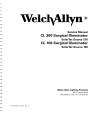
ServiceManual
CL 300 Surgicalllluminator
SolarTecSource270
CL 100Surgicalllluminator
SolarTecSource100
WelchAllyn Lighting Products
4 6 1 9J o r d a nR o a d
Skaneateles
Falls,NY 13153-0187
PN: LB-MANCLSERVRev.A
Tableof Contents
------1-1
GENERA
I NL F o R M A T T o N
- - 1-1
T E C H N T CH
AE
L L PI N F o R M A T T o N
-----
S E R V I C E N T E R- -S- - -
1-2
WARRANTY
-.----.1-3
SYSTEM
S Y M B o LD E S C R I P T I o N S
-------
1-4
---
--W A R N I N GASN DP R E C A U T I o -N- S
W a r n i n g- - - - - -
1-5
1-5
CautionO P E R A T I NI N
GS T R U C T I o N S
---
1-5
----
1-6
1'6
Conlrols
-'----
PowEO
R N / O FSFw r r c H .
------
F | B EPRo R r
M U L TLI I N K TEMX P A N S I oPNo R T -I N S T A L L A TAI oNNDU S E( o P T I O N A L )
L i c HA
T ] - T E N U A TCTooNNT R o-L- - - L A M PL I F El N D r c A T o R
. - - -- -...-
- 1-8
---1-8
L I G HSTo U R c E
P o w E RS u p p l yw r r HC o N T R oELL E c r R o N r c s
M U L TL| i N K TPMo R T A NM
D U L TLr T N K T
EM
x p A N s r oPNo R T - S E R V T- C E
16
-1-7
---------1-7
-'l-7
P r i n c i p l e sO f O p e r a t i o nR E P L A C E MLEAN
MTP S-
16
-----.
---1-8
---- -1-8
---------1-8
---------
C L E A N T -N- -G- - -
1-9
--1-9
.-
S U R G T CI LALLU M T N A T o R
1-9
------1-9
M U L TL| T N K E
oN
o R T- - - - - - - T xMp A N s r P
-- 1-10
T o o L SR E o U I R E D
---
- -G
-T R o U B L E S H o o T- N
1-11
- - - - - 1-11
... -'I-12
C L 1 0 0S u R G r c AI L
r LUMTNAToR
C L 1 O OS U R G I C IALLL U I \ , I I N AD
T IoSRA S S E M B-L- Y- T E S T# 1 : B L o W NF U s E s
- - 1-12
TEST
W A T TP O W ESRU P P T Y
# 2 :1 O O
T E S T # 3C:o o L r NFGA N- - -
--------
TEST#4: LED/OVEBTEMP
SWITCH
.
1-13
.1-13
- - - -' 1.13
T E s r # s :M r c R oL I N K @
F T B ETR
E s r- - T E S T # 6P: o w E RS u p p L yC A L T B R A I o N
C L 1 O OS U R G I C AIL L U M I N A T oDRI S A S S E M B L Y
PoWER
S U P P LRYE M o V A L
--
- -------
1-13
- 1-14
- - - 1.15
- - 1-15
PLATFoRM
EMoVAL
--------
1-16
F R o NBT E Z ERLE M o V A L
REMoVAL
FANDEFLECToR
--------
1-16
1 16
C H A S SFI A
S NR E M o V A L
L E D / O V E R T EHMAPR N E SRSE M o V A L
L A M PC A B L R
E EMoVAL
I N T E R L oS
Cw
K r r c HR E N t o v A L
PoWER
E N T RM
Y O D U LR
EE M o V A L
1
0
0
S
U
R
G
T
C
I
A
L
L
U
M
TNAT
RoERP A TPFA R T L
CL
Sr s r - - C L 3 0 0S U R G T CI LALLU M T N A T o R
C L 3 O OS U R G I C AIL L U M I N A T oDRI S A S S E M B L Y
TEsr#1:BLowN
FusEs
TEST#2: AuxrLrARy
BoARDlNpurTERMTNALS
T E s r # 3C
: o o L r NFGA N- - - T E s r# 4 : L E DO P E R A T o N
TEST#5: MIcRoLINK@
FTBER
TEST
C L 3 O OS U R G I C AILI I U M I N A T o R
DISASSEMBLY
----I N T E R NMAoLD U LREE M o V A- L
PoWERSUPPLY
REMoVAL
(
p
A
R
r
PCBA
N o .A 4 - 1 0 6 7 0R) E M o V A L
l G N r r oR
RE M o V A L
L | N EF T L T ERRE M o V A L
C H A S SF
I SA NR E M o V A L
PowER
E N T RM
Y o D U LR
EE M o V A L
PLATFoRM
EMoVAL
F R o NB
T E Z ERLE M o V A L
B L o w EFRA NR E M o V A. -L
LAMP
C A B LR
E E M o V A -L- - LLUMTNAT
RoERP A TPR
A R T LSr s r - - C L 3 0 0 S U R G T CIA
'- ------- 1-17
-. -.. - 1-17
- --- 1-17
- - - -' 1-18
-. - _ 1-18
-----
1-19
-- - ----'l 25
- - - 1-27
---- 1-21
- - - - 'l-27
127
-----
1-27
- - - 1-2A
.. - 1-29
------129
129
-------
1,30
.--- -- 1-31
-- . - 1-31
---- 1-32
--------
1-33
------ 1-34
----- 1-34
--------1-34
--- 1 35
----- 1-36
G L o S S A RoYF T E R N 4 S
F I N A LI N S P E C T I o N
C L 1 O OS U R G I C IALLL U M I N A T o R
C L 3 O OS U R G I C IALLL U M I N A T o. .R .
SPEcrFlcAroNS
T H E o R Y oO
FP E R A T I o N
L r G HSr o u R c E
R E P L A C E ML E
AN
MTP SP o w E RS u p p L yw r r HC o N T R oELL E c r R o N r c s
M U L TLI I N K TPMo R T A NM
D U L TLr T N K T
EM
x p A N S t oPNo R T - -
------
1-42
-- 1-43
-.. - 1-43
- 1-43
---
1-45
-----
1-46
------1-46
-------1-46
--- - -- 1-46
---------1-46
,I-47
C L 1 O OS U R G I C AI LLL U M I N A T C
oR
I R C U IDTI A G R A M
--- ----
C L 3 O OS U R G I C AILL L U M I N A T oCRI R C U ID
TIAGRAM
. -. - - - - 1-48
GENERALINFoRMATToN
'100
T h eW e l c hA l l y nC L
S u r g i c al l l u m i n a t oarn dt h e W e l c hA l l y nC L 3 0 0 S u r g i c al l l u m i n a t oprr o v i d eb r i l l i a n t
p
h
y
s
i c i aann ds u r g e o nT. h e l a m p sp r o d u c eh i g hi n t e n s i t yl i g h tn e a r l yi d e n t i c at lo t h e s p e c t r u m
i l l u m i n a t i of n
orthe
o f s u n l i g h tS. p e c i afle a t u r e si n c l u d et h e a b i l i t yt o u s e e i t h e ra C o g e n tO p t i c sM i c r oL i n k @F i b e ro r a c o n v e n t i o n a l
f i b e rb u n d l e .
TECHNTCAL
HELPlNFoRrvrATroN
O n l yf u l l yt r a i n e da n d p r o p e r l ye q u i p p e dp e r s o n n esl h o u l dp e r f o r ma l l s e r v i c ea n d r e p a r r su, s r n gq e n u r n e
t a r r a n t ya n dc o u l d
r e p l a c e m e npta r t sa n dc o r r e c p
t r o c e d u r e sF.a i l u r e
t o d o s o w i l l i n v a l i d a tteh e p r o d u c w
performance.
compromiseinstrumentsafety and
R e a da n d u n d e r s t a nadl l s a f e t yw a r n i n g sa n ds e r v i c en o t e sp r i n t e di n t h i sS e r v i c eM a n u a l a n dt h e O p e r a t i n g
, r phone
M a n u a l sp, a r tn u m b e rL B - I V A N - 1 0 0 W 2 7 0lW
f t .h e r ei s a n yd o u b ta b o u ta n y p r e c a u t i oonr p r o c e d u r ef o
h e l p .o r t o o r d e ra d d i t i o n aclo p i e so f t h e O p e r a t i n M
g a n u a lc, o n t a c t :
Customer Service
Welch Allyn, Inc.
4619 Jordan Road. PO Box 187
SkaneatelesFalls,NY 13153-0187USA
Telephone:
1-315-685-2993o1
1-866-801-8428
FAX:
1-315-685-2999
Techncial Assistance
Telephone:
1-315-685-4233,7:00am-3:00pm(EST)
W h e n c a l l i n gr,e f e rt o t h e m o d e ln u m b e rs h o w no n t h e d a t al a b e l f, o u n do n t h e b a c ko f y o u rS u r g i c al l l u m i n a t o r .
" T r o u b l e s h o o t i"n g p a g e
T e c h n i c aals s i s t a n cies c o n t a i n e d
in
1 1 o f t h i sm a n u a l .
on
PN: LB-MANCLSERVBev.A
Welc$11ytt'
SeRvrceCENTERS
lf you havean equipmentproblemthat you cannotresolve,you may callthe Welch AllynServiceCenternearest
you for assistance.Technicalservicesupportrs availableby telephoneon norma businessdays at the phone
n u m b e r sl i s t e db e l o w .l f y o u a r e a d v i s e dt o r e t u r na p r o d u c t o W e l c hA l l y nf o r r e p a i ro r r o u t i n em a r n t e n a n c e ,
r i t h t h e s e r v r c ec e n t e .n e a r e syl o u .
s c h e d u l et h e r e D a iw
BEFORERETURNINGA PRODUCTFORREPAIRYOU MUST OBTAINAUTHORIZATIONFROM WELCH
ALLYN. AN RMA (RETURNMERCHANDISEAUTHORIZATION}NUMBERWILL BE GIVENTO YOU BY OUR
SERVICEPERSONNEL.BE SURETO NOTETHIS NUMBER ON THE OUTSIDEOF YOUR SHIPPINGBOX.
RETURNSWITHOUTAN RMA NUMBERWILL NOT BE ACCEPTEDFORDELIVERY.
USA CUSTOMERS
CANADA CUSTOMERS
Welch Allyn, Inc., U.S.A.
4 6 1 9J o r d a nR o a d
, Y 13153-0187
S k a n e a t e l eFsa l l sN
Tel:1-315-685-2993
Fax:315-685-2999
Welch Allyn, Ltd., Canada
'160
M a t h e s o nB l v d .E . ,U n i t# 2
M i s s i s s a u g aC,a n a d aL 4 Z 1 V 4
Tel:905-890-0004
Fax:905-890-0008
INTERNATIONALCUSTOMERS
Welch Allyn, GmbH
Zollerstrasse
24
72417 JunEngen,Germany,
fel: 011-49-7
477-9211-73
Fax.011-49-7477-9271-93
Welch Allyn, Ltd., Singapole
300 BeachRoad,#25-08
The Concourse
Singapore199589
Tel:011 65-291-0882
F a x :0 1 1 - 6 5 - 2 9 1 - 5 7 8 0
Welch Allyn, Ltd., Australia
Metro Center
Unit 5 38 SouthStreet
R y d a l m e r eN, S W2 1 1 6 ,A u s t r a l i a
T e l :0 11 - 6 1 - 2 9 4 - 1 8 3 - 1 5 5
F a x :0 11 - 6 1 - 2 9 4 - 1 8 3 - 6 5 0
Welch Allyn, China
Room708, 22'/ lluang Pi Road,North
CentralPlaza
S h a n g h a2i 0 0 0 0 3
P R .C h i n a
T e l :0 1 1 - 8 6 - 2 1 - 6 3 2 7 9 6 3 1
Fax. O11'86-21-63279632
Welch Allyn, Japan
Bon Marusan8F,3-5-1Kanda
J i n b o - C h oC, h i y o d a - K u
T o k y o1 0 1 - 0 0 5 1
Japan
T e l :0 11 - 8 1 3 - 5 2217 3 9 1
f ax. 0 11-813-3261-7372
LATIN AMERICANCUSTOMERS
MD Intemational
11300 N.W. 41st Street
M i a m i ,F L 3 3 1 7 8U S A
Tel: l-305-669-9003
F a x :1 - 3 0 5 - 6 6 9 - 1 9 7 1
1 2
WELCHALLYN
WARRANTY
W e l c hA l l y nw a r r a n t st h e C L 3 0 0 o r C L 1 0 0S u r g i c al l l u m i n a t owr h e n n e w t o b e f r e e o f d e f e c t si n m a t e r i aal n d
workmanshipand to pertormin accordancewith manufacturer's
specificatrons
when subjectto normaluse and
s e r v i c ef o r a p e r i o do f o n e y e a rf r o m d a t eo f p u r c h a s ter o m W e l c hA l l y no r a n a u t h o r i z eadg e n t .W e l c hA l l y nw i l l
e i t h e rr e p a i ro r r e p l a c ea n y c o m p o n e n tfso u n dt o b e d e f e c t i v eo r a t v a r i a n c e
f r o m m a n u f a c t u r e rs' sp e c l f i c a t i o n s
w i t h i nt h i st i m e a t n o c o s tt o t h e c u s t o m e rl.t s h a l lb e t h e p u r c h a s e r r' se s p o n s i b i l ittoy r e t u r nt h e i n s t r u m e nt to t h e
a u r h o r i z eddi s t n b J t o ra,g e n t .o r s e r v i c er e p r e s e n t a t r v e .
WelchAllynwarrantsthe lampto be free of defectsin materialsand workmanshiptor a periodof 6 monthsfrom
t h e d a t eo f p u r c h a s eT. h i sw a r r a n t yd o e sn o t c o v e rt h e l a m pf o r b r e a k a g o
e r f a i l u r ed u e t o t a m p e r i n gm
, isuse,
n e g l e c ta, c c i d e n t si m
, p r o p e irn s t a l l a t i o m
n ,o d i f i c a t i o n
, i p p i n go, r f r o m i m p r o p em
sh
r aintenance
se
, r v r c eo, r
procedures.
cleaning
Thrswarrantyis void if the instrumentis not used in accordancewith manufacturer's
recommendations
or if
r e q u i r e ds e r v i c ei s p e r f o r m e db y o t h e rt h a nW e l c hA l l y no r a n a u t h o r i z eadg e n t .P u r c h a s d
e a t ed e t e r m r n e s
w a r r a n t yr e q u i r e m e n t sN.o o t h e re x p r e s so r i m p l i e dw a r r a n t yr s g r v e n .
P N :L B M A N C L S E R VF e v .A
Velc$1yt
'
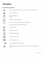
SYSTEM
SYMBoLDEscRtPTtoNs
A
A
A t t e n t i o nR
: e a dO p e r a t i n g
M a n u afl o r W a r n i n g sP, r e c a u t i o nas n
, d I n s t r u c t i o nf so r U s e
Caution- Hot SurfaceArea
A
Ra^la^a
tr,,c6
ec
lr,4ert orl
250V5A
5A,250V
A
- Highvoltage
WARNING
is present
I
Symboo
l n p o w e rs w i t c hi n d i c a t eps o w e ri s o f f w h e n p r e s s e d
S y m b o il n e l e c t r i c ar la t i n gs i g n i f i e A
s C m a i n sp o w e r
+
@
|- ^.*l
|
|f
l
H i g hI n t e n s i t yL i g h t
ProtectiveEarthGround
t4__l
Temperature
Storage
Range
@
Maximum
Storage
Humidity
tr
aPxg
T y p eB F e q u r p m e n tC, l a s sI
Not protectedagainstthe ingressof water
Manufacturedin accordancewith the relevantregulationsand technicalrequirementsof
Japan.
WELCHALLYN
WARNINGS
AND PRECAUTIoNS
e
/-\
l\
WARNING
.
K e e oo u t o l r e a c ho f p a t i e n t .
.
N o t s u i t a b l et o r u s e i n t h e p r e s e n c e
of a flammable
a n e s t h e t im
c i x t u r ew i t h a i r o r w i t h o x y g e no r
n i t r o u so x i d e .
.
Disconnectfrom the patientbeforethe dischargeof a cardiacdefibrillator.
.
E L E C T R I C ASLH O C KH A Z A R DD
. o n o t r e m o v et h e t o o c o v e r
.
.
.
.
.
.
.
.
r
lA
R o u t i n e ley x a m i n et h e p o w e rc o r da n d p i u g .D o n o t u s e i f i n s p e c t i o rne v e a l sd a m a g eR
. e p l a c eo n l y
with approvedhospitalgradepower cord and plugwith appropriateelectricalrating.
Do not olacethe exooseddistalend of the Micro Link@Fiberor fiber bundleattachedto eithera
headlightor other accessory.Failureto observethese precautionsmay resultin burnsto skin,
c l o t h i n go, r o t h e rm a t e r i ailn a d v e r t e n tpl yl a c e di n f r o n to f t h e M i c r oL i n k @F i b e ro r f i b e rb u n d l e .
H i g he n e r g yr a d i a t e d
l i g h tg u i d e dt h r o u g he n d o s c o p em
s a y g i v er i s et o h i g ht e m p e r a t u r eisn f r o n to f
t h e l i g h to u t l e ta n dt o t h e t i p o t t h e i n s t r u m e n t .
Use care not to pointthe distalend of the fiber or headliqhtdirectlyat the eye when unit is operating.
T h e b r i l l i a nl ti g h to u t p u tf r o m t h e u n i tc a n c a u s ee y e i n j u r yp e r R P 2 7. 1 ( ' 1 9 9 41 9 9 5T h r e s h o l L
dimit
I n d i c e sF, i n adl r a t tM a r c h
V a l u e s{ o r C h e m i c aSl u b s t a n c easn dP h y s i c aAl g e n ta n dB i o l o g i c aElx p o s u r e
3,1995).
Appliedpartsattachedto this equipmentshouldbe approved1) to the MedicalDeviceDirective(93/
TestingLaboratory(UnitedStates),and3) by
42/EEC)(Europe),2) approvedby a NationallyRecognized
(Canada)
a StandardsCouncilof Canadaaccreditedlaboratory
to the appropriatemedicalstandards.
The use of non-approved
componentsmay compromisesafety.
D u r i n gl i { et h r e a t e n i npgr o c e d u r e si t,i s r e c o m m e n d etdo h a v ea b a c k u pL i g h ts o u r c ea n da n a d d i t i o n a l
r e o l a c e m e nl at m o .
m a yc a u s ep r e m a t u r e
T h e l i g h ts o u r c el a m p sa r e h i g h l yp r e s s u r i z e ad n, yd a m a g eo r i m p r o p ehr a n d l i n g
f a i l u r eo r e x p l o s i o n
of the lamp.
The light sourcelampsare hot immediatelyafter use,allow the lampto cool for five (5)minutesafter
peakin the light Sourcesapproximately
60 secondsafterthe LightSourceis
operation.Temperatures
poweredoff.
CAUTION
. Do notplaceanythrng
on topof theLightSource.
Do notstoreliquidabovethe LightSource.
.
.
C l o g g e do r b l o c k e dv e n t sm a yc a u s eL i g h tS o u r c eo v e r h e a t i nagn dw i l l r e s u l ti n t h e r m a sl h u t d o w n .
K e e pt h e L i g h tS o u r c ec l e a ro f a n yo b s t r u c t i o n s .
F u l l yc l o s et h e a t t e n u a t obr e f o r et u r n i n go n t h e L i g h tS o u r c eo r w h e n o p e r a t i o n ablu t n o t i n u s e .
PN: LB-MANCLSERVRev.A
Welc$11yn.
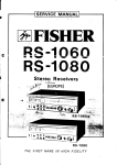
OPERATTNGlNsrRucloNs
CONTROLS
PowERON/OFFswrrcH
l
"Hospital
P l u gh o s p i t agl r a d eP o w e rC o r di n t oa g r o u n d e d" H o s p i t aG
r a d e "o r
U s e " r e c e p t a c lteo e n s u r e
grounding
reliability.
PressMain PowerSwitch ON (l pressedin).
T h e l a m pw i l l c o n t i n u et o o p e r a t eu n t i l t h ep o w e rs w i t c hi s m o v e dt o t h e O F Fp o s i t i o n( O p r e s s e di n ) .l f t h e l a m p
cannotbe startedor stops operatingsee Section8: Troubleshooting.
NOTE:
.
.
l t i s n o r m a tl o h e a rc l i c k i n g( 1 0p u l s e so r l e s s )b e fo r e t h e l a m pi s s t a r t e d .
To insureproperoperation,wait thirty (30)secondsbetween on/off cycles.
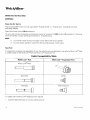
F|BERPoRT
To increasethe versatilityand applicability
of use,the LightSourcesare designedto use eithera Micro Link@Fiber
o r a t i b e rb u n d l ev i at h e M u l t iL i n k r MP o r ta n d M u l t iL i n k r ME x p a n s i oP
nort.
Cable Gompatibility
Multi Linkn Port
Table
Multi Link- Expansion Port
Micro Link@
Fiber
KarlStorz
ACMI
Olympus
Wolf, Dyonics
F o rc a b l e sw i t h n o M u l t i L i n k r ME x p a n s i oP
n o r tr e q u i r e d :
1 . C l o s et h e l i g h ta t t e n u a t oor r t u r nt h e L i g h tS o u r c eo f f .
r 6
WELCHALLYN
2 . C o n n e ct h e l n s t r u m e net n d o f t h e M i c r oL i n k @
F i b e ro r f i b e rb u n d l et o t h e i n s t r u m e n t .
, n t i lf u l l ye n g a g e d( s n a ps o u n d )t,h e L r g h tS o u r c ee n d i n t ot h e M u l t iL i n k r MP o r t .
3 . I n s e r tu
4 . T u r no n L i g h tS o u r c e .A d j u s t h e l i g h ta t t e n u a t otro t h e r e q u i r e di l l u m i n a t i ol n
evel.
MULT|L|NK'" ExpANsroNPoRT- lNsrALLATroN
aNo UsE (oproNAL)
CAUTION:
T h e M u l t iL i n k r ME x p a n s i oP
n o r tc o n t a i n so p t i c ael l e m e n t st h a tc a n b e c o m ed a m a g e di f d r o p p e d
or aouseo.
NOTE:
T h e M u l t iL i n k r M
Fiber
E x p a n s i oPn o r tm u s tb e f u l l ye n g a g e di n t ot h e L i g h tS o u r c eb e f o r ei n s e r t i n g
Bundle.
To use the l\4ultiLinkrMExpansionPort performthe followingoperations:
1 . C l o s et h e l i g h ta t t e n u a t oor r t u r nt h e L i g h tS o u r c eo f f .
2 . R e m o v ei,f a n y ,M i c r oL i n k @
F i b e ro r f i b e rb u n d l ef r o m t h e M u l t i L i n k r MP o r t .
3 . I n s e r t h e M u l t iL i n k r ME x p a n s i oP
n o r t ,p r e s sa n dt u r n c l o c k w i s eu n t i li t l o c k si n t op l a c e .
4. Connectthe fiber bundleto the instrument.
5 . I n s e r tu
, n t i lf u l l ye n g a g e dt,h e L i g h tS o u r c ee n d o f t h e f i b e rb u n d l ei n t ot h e M u l t iL i n k r ME x p a n s i oP
no r t .
6 . T u r no n L i g h tS o u r c e .A d j u s t h e l i g h ta t t e n u a t otro t h e r e q u i r e di l l u m i n a t i ol n
evel.
To removethe Multi LinkrMExpansionPort performthe followingoperations:
1 . T u r nt h e L i g h tS o u r c eo f f .
2 . R e m o v et h e f i b e rb u n d l e .
3. Turnl\,4ulti
LinkrMExpansionPortcounter-clockwise
until unlockedand remove.
LrcHTATTENUATToN
CoNTRoL
M o v i n gt h e i l l u m i n a t i ownh e e lu p *
i n " r " u r " . l i g h to u t p u t .M o v i n gt h e w h e e ld o w n -
r e d u c e sr r g n o
t utput.
LAMP LrFElNDrcAToR
A y e l l o w i n d i c a t o rl i g h t l o c a t e do n t h e c o n s o l ew i l l l i g h t w h e n t h e r e i s a p p r o x i m a t e l y5 0 h o u r s
r e m a i n i n go n t h e l a m p . A n e w R e p l a c e m e n tL a m p s h o u l d b e a v a i l a b l ea t t h i s p o i n t . O n c e t h e
r e m a i n i n gh o u r s h a v e b e e n e x h a u s t e dt h e l a m p w i l l t u r n o t f .
PN: LB-MANCLSERVREV.A
Welc\Allyn.
PRINCIPLES
OF OPERATION
LtcHTSouRcE
T h e S u r g i c al l l u m i n a t o rcso n s i s o
t f anenclosure
h o u s i n ga h i g hi n t e n s i t yl a m p ,p r o p r i e t a royp t i c apl l a t f o r mu, s e r
controlsand indicators,and a power supplywith controlelectronics.Coolingis providedvia internalfans. In the
eventthat the fan(s)malfunctionsor if adequateair flow is blockedand/orthe internaltemperatureof the device
exceedsthe engineeringspecifications,
an internalthermalprotectionmechanismwill automatically
shut off
power to the lamp. After cooling,the LightSourcesmay be restarted.
REPLAcEMENT
LAMPs
T h e l a m p sa r e h i g hp r e s s u r eh, i g hi n t e n s i t ya n d l o n gl i f eL i g h tS o u r c e s T
. h e ya r e m o u n t e di n t oa p a t e n t e dl a m p
f i x t u r ew h i c h i s d e s i g n e dt o a l l o wb o t he a s ya n d r a p i de x c h a n g ei n t h e f i e l da s w e l l a s e n s u r i n gp r e c i s ea l i g n m e n t
t o t h e o p t r c apl l a t f o r m .
PowERSupply wrrx CoNTRoLELEcrRoNtcs
All the electricityto the LightSourceis controlledthroughthe ON/OFFswitch. Powerto energizeand operatethe
lamp,tans,and controlcircuitryis providedby a custom designed,wattageregulated,switchingpower supply.
The operationallife of the lamp and lamp life indicatorare controlledby a lamp voltagemonatoring
circuit.
MuLr LtNxn PoRTANDMULT|L|NK* ExpANsroN
PoRT
Internal,to both the Multi LinkrMPortand Multi LinkrMExpansionPort,are patentedcouplingopticsand mechanics
designedto producethe highestoutput powers. Internalto the LightSourcesare fans and heatsinksdesignedto
r e d u c et e m p e r a t u r east t h e o p t i c acl o u p l i n gj o i n t st h e r e b ym i n i m i z i ntgh e p o s s i b i l i toyf d a m a g et o M i c r oL r n k @
F i b e ra n df i b e rb u n d l e s .
1 B
WELCHALLYN
SERVTCE
CLEANTNG
1 . P r i o rt o c l e a n i n gt ,u r nt h e p o w e rs w i t c hO F Ea n dd i s c o n n e cpt o w e rs o u r c ef r o m b o t ht h e L i g h tS o u r c ea n d
t h e w a l lo u t l e t .
2 . C l e a nt h e e x t e r n asl u r f a c e sb y w i p i n gw r t ha c l o t hd a m p e n e dw i t h 1 0 % b l e a c hs o l u t i o nD
. O N O TI M M E R S E .
r
R o u t i n e l iyn s p e c a
t n dc l e a na l l a i ri n t a k e s/ o u t f l o w sa t t h e r e a ro f t h e c h a s s i sf o r l i n to r o t h e rd e b r i s .
.
F o l l o wt h e m a n u f a c t u r e ri'nss t r u c t i o nwsh e n C l e a n i n tgh e f i b e rb u n d l e so r a c c e s s o r i euss e dw i t h t h e l i g h t
source.
3 . W i p et h e p o w e rc o r dw i t h a c l o t hd a m p e n e dw i t h 1 0 7 ob l e a c hs o l u t i o na n dw a t e r .D O N O TI I V I M E R S E
D .O
N O TR E C O N N E CW
TE T .
4 . D O N O Tw i p e d o w n a n y l e n s e so r w i n d o w s .
5 . D O N O Tp l u gt h e p o w e rs o u r c ei n t oa w a l l o u t l e tu n t i li t i s t h o r o u g h ldyr y .
SURGtcAL
ILLUMtNAToR
T h e c o n s o l em a y b e c l e a n e du s i n ga c l e a ns o f t c l o t hw i t h t h e f o l l o w i n gc l e a n i n g
agents:
E n z y m a t iS
c o l u t i o n( E n z o l )
lsopropylAlcohol
H y d r o g e nP e r o x i d 3
e% USP
2 % Gl u t a r a l d e h y dSeo l u t i o n
Soapand Water
'lOo/o
b l e a c hs o t u t t o a
n n dw a t e r
C A U T I O N : D o n o t s p l a s hc l e a n i n g
a g e n t si n t oa n y o p e n i n g ss,e a m so r e l e c t r i c aclo m p o n e n t s .
MULT|L|NK* ExPANsroN
PoRT
The outsidesurfacesmay be cleanedwith a soft cloth usingthe following:
i s o p r o p yAl l c o h o l
Soapand Water
The glasssurfacesmay be cieanedby the followingmethods:
A cottonswab moistenedwith lsopropylAlcohol
Blow with dry compressedair
NOTE: Use care in cleaningthe opticalsurfacesof the Multi LinkrMExpansionPortto preventscratches.
PN:LB-MANCLSERVRev.A
1-9
'IVelc$;1*.
TooLsREoUIRED
.
"
Slottedscrewdriver,lessthan 6 long
.
# 1 P h i l l i pS
s c r e w d r i v elre, s st h a n6 " l o n g
.
# 2 P h i l l i pS
s c r e w d r i v elre, s st h a n6 " l o n g
.
O p e ne n d w r e n c hs e t - E n g l i s ho r 5 / 1 6 "
.
N e e d l en o s ep l i e r s
.
N u t D r i v e rS e t- E n g l i s ho r 3 / 1 6 " , 1 1 4 " , 5 1 1 6 "
.
N u t D r i v e rS e t- M e t r i co r 1O m m
.
D e e pw e l l s o c k e ts e t a n dw r e n c h( 2 )- C L 1 0 0S u r g i c al l l u m i n a t o r
.
N o n - c o n d u c t i vpeo t a d j u s t i n g
t o o l- C L 1 0 0S u r g i c al l l u m i n a t o r
.
Lightoutputpower meter with head.CoherentLasermate1D or equivalent(meter),HeadModel 1d10- CL
1 0 0S u r g i c al l l u m i n a t o r
.
Laght
outputmeter- Labsphere
ModelFIMS-400P
or equivalent
thatmeasures
in lumens- CL300Surgical
llluminator
o
C a I b r a t e oR M S D r g i t aM
l u l t i m e t e (r D M M )
1,10
WELCHALLYN
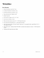
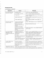
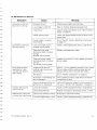
ThouBLESHoorNG
CL 1o0 SURGTCAL
ILLUMTNAToR
Symptom
L a m pf a i l st o s t a r ta n d
f a n sa r e n o t r un n i n g .
Cause
No power to unit
C h e c kp o w e rs u p p l yc o r da n do u t l e t
Linevoltageis <90 VAC
Referto HospitalEngineering
department
"Test
#1: Blown
Inspect,replaceand retest.Go to
F u s e s "o n p a g e1 2 .
F u s e sb l o w n
Safetyinterlockopen
Power supplyfailure
Lampfailsto start and
f a n sa r e r u n n i n g .
| ^'n^ ^h' '+^ ^al ^t.^.
Lo, r,P r,,urr u, I o, rel
operatingfor a few
m inutesand restartsafter
coolrng.
I n di c a t o rl i g h to n a n d
lampshuts off
Remedy
C h e c ka n dt i g h t e ns l o t t e ds c r e wo n l a m pf i x t u r e
accessdoor
"Test
#2: 100WATTPower Supply"on
Go to
p a g e1 3
L a m pn o t i n l i g h ts o u r c e
( a u d i b lcel i c k i n gh e a r d )
I n s t a lal 1 0 0 Wr e p i a c e m e nl at m p ,m o d e l9 0 1 3 3 .
Defectivelampcable
(discolored,
bent or broken
prongs)
( a u d r b lcel i c k i n gh e a r d )
Reolace
a n d r e t e s tl a m oc a b l e .
Defectivepower supply
(discoloreb
de
, n to r b r o k e n
prongs)
( n oa u d i b l ec l i c k i n gh e a r d )
I n s p e cw
t i r i n ga n di f i t i s f i n e ,r e p l a c ea n dr e t e s t
power supply.
I n a d e q u a taei rf l o w f o r
c o o l i n gL, i g h tS o u r c eo v e r
lemperalUre
F a nf a i l u r e
A i l o w2 " ( 5 1 m m )c l e a r a n caet b a c ko f u n i t ;i n s u r e
vents are cleanand not
that air intake-outflow
blocked.Allow unit to cool and then restart
"
'l
"Test
#3: CoolingFan on page 3.
Go to
l l l u m i n a t oi sr o v e r h e a t i nngo t
d u et o c l e a r a n c e .
Verifyoperationof fans.Cleanfans and internal
componentsof dust.
Lamp rs at the end oi life,but
a m b e rL E Di s i n o p e r a t i v e .
VerifyLED flickerson when it is first turnedon. lf
"Test
not, go to
#4: LED/OvertempSwitch" on
p a g e1 3 .
L a m pl i f ee x c e e d e d .
I n s t a lal 1 0 0 Wr e p l a c e m e nl at m p ,m o d e l9 0 ' 1 3 3 .
L a m pc a b l ed e f e c t r v e .
R e p l a c ei ' p r o n g sa r e d i s c o l o r e db.r o k e no. r b e n t
Powersupplyout of
calibration.
"Test
To go
#6: Power SupplyCalibration"on
p a g e1 4 .
R e p l a c e m e nLta m pw i l l
Lampis not orientedcorrectly Rotatelamp 180' and re-insert
not seat into LightSource
I n c o r r e cRt e p l a c e m e nLta m p I n s t a lal 1 0 0 Wr e p l a c e m e nl at m p ,m o d e l9 0 1 3 3 .
P N :L B - M A NC L S E R VB e v .A
Velc$11yn.
Symptom
Low l i gh t oulpul
F i b e rb u n d l ew i l l n o t
Installin LightSource
"
"
A u d i b l e c l i c k i n go r
a r c i n gs o u n dd u r i n gt h e
l a m pi g n i t i o np r o c e s s
Cause
Remedy
Fiber
D a m a g e dM i c r oL i n k @
o r f i b e rb u n d l e
C h e c ke n d so f M i c r oL i n k @F i b e ro r f i b e rb u n d l e
f o r d a m a g eR
w i t h n e w M i c r oL i n k @
Fiber
. eplace
"Test
o r f i b e rb u n d l eG
. ot o
# 5 : M i c r oL i n k @F i b e r
'13.
T e s t "o n p a g e
Fiberbundlenot connected
correctly.
Re-insertf iber bundlecorrectly.
L a m pn e a re n d o f u s a b l el i f e
l n s t a l l a1 0 0 Wr e p l a c e m e nl at m p ,m o d e l9 0 1 3 3 .
F i l t e ra s s e m b l yo n p l a t f o r m
contamrnated.
C l e a no r r e p l a c ef i l t e ra s s e m b l ya s n e c e s s a r y .
Minors dirty.
Cleanmirrors.
B r o k e nm i r r o r s .
Replaceplatform.
M i s a l i g n em
d i r r o r s( p o s s i b l e
if unit suffersdamage)
lf abovestepsfail to improveoutput, replaceand
retestplatform.
Dirtyor damagedinternal
mooute.
Inspect,clean,and replaceif necessary.
"Operating
Instructions"
on page6
Usecompatible
bundle
design
N o t a c o m p a t i b l fei b e rb u n d l e See
"Operatrng
I n s t r u c t r o n so"n p a g e6
I n s t a l l / F e m o vMeu l t i L i n k r M
ExpansionPort
See
Multi LinkrMExpansionPort
installed
RemoveMulti LinkrMFxpansionPort
No problem
Normaloperation
CL lOOSURGICAL
ILLUMINAToR
DISASSEMBLY
NOTE: For all tests, remove9 screws from top cover.
NOTE: Do not operateunit with the top cover removedfor more than 5 minutesor the unit will overheat.
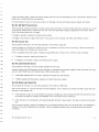
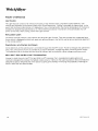
TEST#1: BLowN FUsEs
The purposeof this test is to determinethe sourceof a short circuitcausingfusesto blow. Referto the Block
D i a g r a mo n p a g e4 7 .
Replaceand retestthe fuses. lf unit functionsnormally,inspectfuses that were blown. lf solderis meltingout of
the end of the fuse and the glassis not blackened,removeand replacethe power entry module.Thisfault occurs
when the prongof the fuse holdermakespoor contactwith the fuse. The prongwill look discoloredand pitted
where it contactsthe fuse.
WELCHALLYN
l f t h e f u s eb l o w sa g a r nI,n s p e ctth e p o w e rs u p p l ya n dt h e w i r i n gt o r d a m a g e do r b u r n tc o m p o n e n t sR. e m o v ea n d
replaceany visuallydefectivecomponents.
l f v i s u a Il n s p e c t i odno e sn o t y i e l da n ye v i d e n c eo f d a m a g er, e m o v ea n d r e p l a c ep o w e rs u p p l ya n d r e t e s t .
IEST#2: lOOWATT PowERSUPPTY
V e r i f yo p e r a t i n vgo l t a g ei s p r e s e n ot n p o w e rs u p p l yi n p u tt e r m i n a l sC. o n n e c m
t e t e ra n ds e t t o v o l t sA C t o J 1 a n d
J 2 t e r m i n a l sW
. h e n p o w e ri s a p p l i e dt o t h e u n i t ,v e r i f yt h e o p e r a t i n vgo l t a g ei s d i s p l a y e od n t h e m e t e r .N O T E :
Verifythe lampaccessdoor is closed.
lf voltageis present,repraceand retestpower supply.
l f v o l t a g ei s n o t p r e s e n ti,n s p e ct h e f u s e s ,w i r i n g ,p o w e re n t r ym o d u l e l,i n ef i l t e r a
, n d i n t e r l o c sk w i t c h .
TEST#3: CooLINGFAN
The purposeof this test ls to verifythe operattonof the lampcoolingtan.
V i s u a l l iyn s p e c ft o r a b r o k e nt a n .W h e nt h e u n i t i s p o w e r e du p , l o o kf o r a f a n n o t t u r n i n g l.f f o u n d ,r e m o v et o p
c o v e ra n di n s p e c ft a n .R e p l a c e
a n y b r o k e nf a n s .
lf fan is inoperativeand not broken,measureusingDMM set for VoltsDC for 12VDCon fan connector.
.
lf voltageis present,replaceand retestfan.
.
lf voltageis not present,replaceand retestpower supply.
IEST#4: LED/OVERTEMP
SwITcH
The purposeof this test is to veriiy properoperationof the LED.
Visuallyinspectthat LED/overtempswitch harnessis connectedto the power supply.Verifycontinuityof wiring
a n d L E Dw i t h D M M s e t t o t h e D i o d eS c a l e D
. M M s h o u l dr e a d= . 7 V D C .
.
l f t h e D M M r e a d i n gd o e sn o t m a t c h ,r e p l a c ea n d r e t e s t h e L E Dh a r n e s s
r
l f D M M r e a d i n gm a t c h e sa b o v e ,r e p l a c ea n d r e t e s t h e p o w e rs u p p t y .
TEST#5: MIcRo LINK@FIBERlEsT
The purposeof this test is to verifythe operationof the Micro Link@Fiber.
W i t h t h e i l l u m i n a t oorn , c o n n e c t h e f i b e ra n dt h e h e a d l i g h O
t . v e ra d i s t a n c eo f a t l e a s tf i v et e e t ,a d j u s t h e s p o t
d r a m e t et'o t h e l a r g e sst t z e .
.
l f t h e i n t e n s i t yo f l i g h ti s n o t c o n s i s t e ntth r o u g h o utth e l i g h ts p o ta n dr o t a t i n gt h e d i s t a e
l n d c o n n e c t odr o e s
n o t c a u s et h e s h a p et o c h a n g et,h e h e a d l i g hi ts t h e m o s t l i k e l yc a u s eo f t h e f a u l t
.
l f t h e i n t e n s i t yi s n o t c o n s i s t e nwt i t h a l t e r n a t i nlgi g h ta n dd a r kr i n g sp r e s e n tt,h e f i b e ri s b r o k e na t t h e d i s t a l
O v e rt h e s a m ed i s t a n c ea, d j u s t h e h e a d l i g ht to t h e s m a l l e sdt i a m e t e sr p o t .A t t h i s a d j u s t m e n t h
, e h e a d l i g hi ts
f o c u s e dl.t a n y s p o t i r r e g u l a r i t i e
a sr e p r e s e n th, o l dt h e h e a d l i g hstt e a d yw h i l er o t a t i n gt h e d i s t a e
l nd(black)
connector.
PN: LB-MAN-CLSEBV
Rev.A
1,13
Welc\Allyn'
.
lf the locationof the defectsmove,removethe fiber,cleanthe end with distilledwater,reconnectthe unit,and
test. Replacethe fiber if detectsare still present.
.
lf the locationof the defectsremainstationary,
the fault is within the headlight.
TEST#6: PowERSUPPLY
CAL|BRAT|oN
The purposeof this test is to verifythe operationof the power supply.
Applypower to unit,once the lamp lights,connectthe DIVIV(setto volts DC)to the lampcablewires on the
p o w e rs u p p l yT. h e p o s i t i v el e a do f D M M t o t h e H V + t e r m i n aol n t h e p o w e rs u p p l ya n dt h e n e g a t i v el e a do f t h e
D M M t o t h e L a m pR e t u r n- t e r m i n aol n t h e p o w e rs u p p l yW
. A R N I N GD: o n o t c o n n e c tD I V Mt o w i r e sp r i o rt o
t u r n i n gt h e u n i to n .W h e n t h e l a m pi g n i t e st,h e r ei s a p p r o x i m a t e2l y5 k Vo n t h e t e r m i n a l w
s h i c hc o u l dd a m a g et h e
D M M . M o n i t o rt h e v o l t a g ed i s p l a y eodn t h e f l u k ew h e n t h e L E Df i r s tt u r n so n .V e r i f yt h e v o l t a g ei s b e t w e e n1 7 . 0 0
and18.00v.
'
lf the voltageis less than 17.00VDC,removeand replacethe power supplyor returnthe unit for recalibration.
l f t h e v o l t a g ei s b e t w e e n1 7 . 0 0 V D C
a n d 1 8 V D Cr, e m o v ea n d r e p l a c et h e l a m pf i x t u r e .
o
lt the voltageis more than 18.00DC,contactthe Welch AllynTechnicalServicesDepartmentat
1-315-685-2993or 1 315-685-4233,
7:00am-3:00pm(EST).
WELCHALLYN
ILLUMTNAToRDrsAssEMBLy
CL 100 SURGTCAL
PowERSUPPLY
REMoVAL
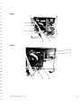
'l
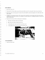
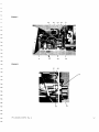
. Bemovethe 9 screwssecurinqthe toDcoverand removethe cover.
2 . R e m o v et h e 3 s c r e w sf r o m t h e b o t t o ms i d eo f t h e b a c kp a n e .
3 . D i s c o n n e cwt i r e sf r o m J 1 a n dJ 2 o n t h e p o w e rs u p p l v D
. i s c o n n e cf at n c o n n e c t ofrr o m J 4 .
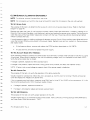
4.
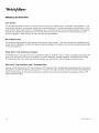
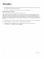
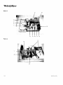
Removethe 2 screwsfrom the bottom chassis,securingthe centerbaffle(seefigurebelow).
lC"
Screws
s e c u r i n gc e n t e r
baffleto bottom
c h a s sr s
o
o
w
5 . R e m o v et h e n u t t h a ts e c u r e st h e c e n t e rb a f f l et o t h e b a c kp a n e l .
6 . Pullbackpanelout and move to the platformside of the chassisto garnaccessto the backof the power
supply.
PN: LB MAN'CLSERVRev.A
1 1 5
Welc$;1yt '
7 . Removethe two white lampcablewires and disconnectthe 4 wire connector.Removethe supplyand baffle.
8 . Removethe 4 screws from the cornersof the power supply.Removesupply.
9 . Reinstallatio
i snt h e r e v e r s ep r o c e s sw i t h t h e b r o w nw i r e g o i n gt o J 1 a n dt h e b l u ew i r e g o i n gt o J 2 . T h e l o n g e r
of the two lampcablewires attachesto the (+) lamp HV terminaland the shorterwire attachesto the (-)lamp
"
r e t u r n .R e f e rt o P h o t o8 " o n p a g e2 4 t o c o n n e c t h e H V + a n d l a m pr e t u r n- t e r m i n a l sa s s h o w n .
PLATFoR'U
REMovAL
'L
Remove9 screwssecuringtop coverand removethe cover.Removethe 5 screws securingthe front bezelto
t h e b o t t o mc h a s s i sa n d p u l lf r o n tp a n e lo u t f r o m c h a s s i sR
. e m o v et h e l a m pf r o m t h e p l a t f o r m .
2. Removethe 2 screws from the fan deflectorassemblv.
3. Removethe 4 screwsf rom the cornersof the platform.
4. As necessary,removethe 2 screwsfrom the f ilterassembly.
. einstallatio
5 . R e m o v et h e p l a t f o r mR
i snt h e r e v e r s ep r o c e s sI.n s t a l l t h ef r o n tb e z e a
l n d c h e c kf o r p r o p e r
movementof attenuator.Loosenplatformscrewsand repositronas necessary.
FRONT
BEZELREMoVAL
1. Remove9 screwssecuringtop coverand removethe cover.Removethe 5 screwssecuringthe front bezelto
t h e b o t t o mc h a s s i sa n d p u l lf r o n tp a n e lo u t f r o m c h a s s i s .
2. Removewires from power switch notingwire localions.Pushon switch from the insideto removethe switch
from the bezel.
3. Usinga sharpknife,removethe blackRry from the LED wires where it mountsto the tront bezel.Once
removed,applyacetoneto the LEDandthe front bezelto weakenthe glue bondand removethe LEDfrom the
front bezel.
4. Installationis the reverseprocess.To attachthe LED,ensureboth paneland LED surfacesare clean.Use
superglue,loctite430 to mount the LED.Use RTVsealantDow Corning737 to sealthe LED,preventingany
l i g h tf r o m t h e i l l u m i n a t opra s s i n gt h r o u g h .
FANDEFLECTOR
REMOVAL
1. Remove9 screws securingtop coverand removethe cover.
2 . R e m o v et h e 5 s c r e w ss e c u r i n g
t h e f r o n tb e z e lt o t h e b o t t o mc h a s s i sa n d p u l l f r o n tp a n e lo u t f r o m c h a s s i s .
3 . Removethe overtempswitch f rom the fan deflector.
4 . Carefullyremovethe heat shrinktubingfrom the fan wiring harness.
5 . Disconnectthe connectorand removeit from the power supply.
6. Installationis the reverseprocesswith installingnew heat shrinktubingover fan connector.
WELCHALLYN
CHAssrsFANREMovAL
T. Remove9 screws securingtop coverand removethe cover.Remove4 screws securingthe fan to the back
pane.
2 . R e m o v eh e a ts h r i n kt u b i n gf r o m t h e f a n c o n n e c t o rD. i s c o n n e catn d r e m o v et h e w i r e t i e sf r o m t h e h a r n e s sa t
t h e p l a t f o r mm o u n t s .R e m o v et h e f a n .
3.
Installation
is the reverseprocess.
LED/OVERTEMP
HARNESS
REMovAL
1. Remove9 screwssecuringtop coverand removethe cover.Removethe 5 screwssecuringthe front bezelto
l ut fromchassis.
t h e b o t t o mc h a s s i sa n d p u l l t r o n tp a n e o
2. Removethe overtempswitch from the fan deflectorassembly.Removethe wire tie f rom the overtempswitch
harnessat the platform.
Usinga sharpknife,removethe blackRTVfrom the LED wires where it mountsto the front bezel.Once
removed,applyacetoneto the LEDand the front bezelto weakenthe glue bondand removethe LEDfrom the
front bezel.
4.
Removethe 3 wire ties and removethe harness.
5.
lnstallationis the reverseprocess.To attachthe LED,ensureboth the paneland the LED surfacesare clean.
( l o c t i t e4 3 0 )t o m o u n tt h e L E D .U s e R T Vs e a l a n(tD o wC o r n i n g7 3 7 )t o s e a lt h e L E Dp r e v e n t i n g
U s es u p e r g l u e
a n y l i g h tf r o m t h e i l l u m i n a t ot or p a s st h r o u g hS
. e ef i g u r eb e l o wf o r r o u t i n go f w i r e s .
LAMPCABLEREMovAL
1. RemoveI screwssecuringthe top coverand removethe cover.Removethe 3 screwsfrom the bottom of the
. l i d eb a c kp a n e tl o t h e s i d e .
b a c kp a n e l .R e m o v et h e n u t s e c u r i n gc e n t e rb a f f l et o t h e b a c kp a n e l S
PN: LB-MAN-CLSERV
Rev.A
117
Welc\ffiytt.
2 . R e m o v et h e n u t f r o m t h e w i r e t i e c l a m ps e c u n n gt h e l a m pc a b l et o t h e b o t t o mc h a s s i sR
. e m o v et h e l a m p
cablefrom the power supplyand removethe cable.
3 . I n s t a l l a t i oi sn t h e r e v e r s ep r o c e s sw i t h t h e l o n g e rc a b l ew r r eg o i n gt o t h e H V +t e r m i n aol n t h e p o w e rs u p p l y
a n d c o n n e c t i n tgh e s h o r t e rw i r e t o t h e L a m pR e t u r n- t e r m i n a lV. i e wt h e u n i tf r o m t h e r e a ra n dc o m p a r et h e
"Photo
H V + a n dt h e L a m pR e t u r n- a r e c o n n e c t e d
8 " o n p a g e2 4 .
a s s h o w ni n
INTERLoCK
SwtrcH REMovAL
1. Removethe 9 screws securinothe toDcoverand removethe cover.
2 . D i s c o n n e ct th e w i r e st r o m t h e i n t e r l o c sk w i t c h .
3. Removethe two nuts from the interlockswitch and remove.
4. Instaliationis the reverseprocess,connectingthe wires to the terminalsmarkedCOM and NO.
PowERENTRYMoDULEREMoVAI
1. Remove9 screwssecuringthe top coverand removethe cover.Removethe 3 screwsfrom the bottom of the
backpanel.Bemovethe nut securingcenterbaffleto the backpanel.
2 . R e m o v et h e 4 s c r e w ss e c u r i n gt h e c h a s s i sf a n . R e m o v et h e w i r e sf r o m P E M .
3 . Removethe two nuts securingthe PElvlto the back panel.Removethe PEM.
4.
lnstallationis the reverseprocesswith the tollowingrequirements:
.
The starwasher is locatedbetweenthe PEM flangeand the paintedsurfaceside of the back panel.
The flat washer is installedon the other side of the paneland is securedwith the nut.
Rotatethe screw so that you can later installthe power cord retainer.
The brown wire is connectedto the terminalmarkedas P on the PEM.The blue wire is connectedto the
t e r m i n am
l a r k e da s N o n t h e P E N /T] .h e g r e e nw i r e f r o m t h e b a c kp a n e li s c o n n e c t e d
t o t h e g r o u n dt e r m i n a lo n t h e P E M .
r 1B
WELCHALLYN
CL 100 SuRGrcArILLUMTNAToR
REpAtR
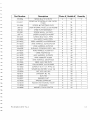
PARTSLtsr
PartNumber
90133
LB-MAN.1OOW27OW
A0-10756
A0-10768
Description
Photo #
Bubble#
Ouantity
l OOWREPLACEMENT LAMP
'l
MANUAL,1OOW2TOW
SOLARTEC
PANEL,
BOTTOIV,
27OW
L A B E LW
, A R N I N GI,L L U I V I N A T O R S
1
1
'l
1
1
12
PAINTED,
SCREW,
XLS
SCREW,
#8-32X 3/8,PHPS
scREW,#6-32X 1/4,PHSS
XLS,BUIVPER,RUBBER,
5/8
1
2
3
1
4
4
1
5
2
1
6
4
10 1- 0 0 6 8
S E M S ,# 6 - 3 2X 5 i 1 6 P H P S
1
1
I
A0-10683
2
2
8
1
A0-10721
TOEXLSCHASSIS
COVER,
KAPTON
TAPE,
IOP COVER,
XLS
9
1
A 0 - t0 8 2 8
,]OOW
P A N E LF, R O N TS, O L A R T E C
3
10
1
u50087
u50081
u50085
u50075
l O O WI N T E R N AM
L O D U L EA S S E M B L Y
3
3
3
3
1 t
1
12
13
1
14
1
3
15
1
3
to
1
3
17
3
3
18
'19
4
4
20
1
4
21
1
1
4
A0-10714
1 0 10 0 3 3
101-0022
016-0005
A 0 - 1 0 71
A0-10856
213-0017
102-0012
44-10650
A4-10647
A0-10746
l O O WF A ND E F L E C T OARS S E M B L Y
l O O WF I L T R
E ASSEMBLY
l O O WA L I G N E DP L A T F O R M
F A N ,C H A S S I SX, L S
PANEL,BACKWAVEPATTERN
POWERENTRYMODULE/LINEFILTER,
FUSED
KEPS,#6.32,W/CONICAL
WASHEB
WtREHARNESS,
l OOW
ON/OFF,
POWER
SUPPLY
XLS
OVERTEMP/LED
SW]TCH
ASSEMBLY
A0-10712
B A F F L EC, E N T E RX,L S
4
A0-'r0843
F O A M ,I G NT O R
4
101-0062
1
'l
1
S E M S ,# 6 3 2 X 9 / 1 6P H P S
5
22
40
23
207-0007
, 2MM
G U A R DF, A N 9
5
24
1
105-0008
C O R D ,R E T A I N I NC
GL A M P
5
I
r06-0011
S T A N D O F#F8, , . 7 5 1
5
208-0016
F U S E5, A S H E E TI I I
6
44-10465
W I R EP, E MT OD I N
6
101-0073
S C R E W#, 8 - 3 2X 3 / 4 " , P H P S
6
010-0016
TUBING,
HEATSHRINK
3/4" BLACK
6
I010061
4 ,H P S
S C R E W#, 4 - 4 0 X 1 1 P
6
25
26
27
28
29
30
31
32
1 0 10 0 3 8
PN: LB-MAN.CLSERV
ReV.A
PLUG,6/25
7
1
4
2
1
4
z.za
4
1
Welc$11*.
Part Number
Photo #
Bubble#
Ouantity
W A S H E H ,C O L O H C O A I I I )
7
33
1
104-0008
104-0007
102-0001
W A S H E RS, E F R A T E D
7
W A S H E RF, L A T
7
NUT,HEX
7
104-0019
W A S H E R#,4 t X I t R N A I T O O T H
7
A0-10864
LAMP,
CABLE,
3OK
8
C A B L ET I E ,S M A L L4 "
8
104 0006
112-0001
124
Description
1
35
36
31
38
39
1
1
2
1
8
WELCHALLYN
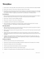
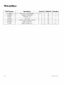
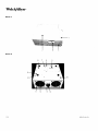
PHoro1
--.
(' lc"
,,
c
<-;-2
5
- =---|'
/
)
e
.
"t-.......-o
a.--.-r
PHOTO2
P N :L B M A N C L S E R VB E v A
.
1-21
Welc$;1*'
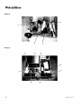
PHoTo3
19
12
10
11
14 18 17 15
PHoTo4
21
WELCHALLYN
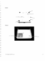
PHoTo5
23
?4
PHoTo6
31
30
PN: LB-MAN-CLSERV
Rev.A
Welc\ffi*'
PHoro7
PHoTo8
WELCHALLYN
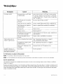
CL 300 SuRGrcAr
ILLUMTNAToR
Symptom
L a m pf a i l st o s t a r ta n d
f a n sa r e n o t r u n n i n g .
Cause
N o p o w e rt o u n i t
C h e c fp o w e rs u p p l yc o r da 1 do u t l e l
Linevoltageis <90 VAC
R e f e rt o H o s p i t aEl n g i n e e r i ndge p a r t m e n t
F u s e sb l o w n
Inspect,replaceand retest.Go to
"
F u s e s o n p a g e2 7 .
Satetyinterlockopen
C h e c ka n dt i g h t e ns l o t t e ds c r e wo n l a m pf i x t u r e
a c c e s sd o o r
"Test
G ot o
# 2 : A u x i l i a rB
y o a r dI n p u tT e r m i n a l s
p
a
g
e
27
an
Powersupplyor auxiliary
boardtailure
L a m pf a i l st o s t a r ta n d
t a n sa r e r u n n i n g .
Lamp shutsoff after
operatingfor a few
m Inutes and restarts
I n d i c a t ol r g h to n a n d
l a m ps h u t so f f
Remedy
"Test
#1: Blown
L a m pn o t i n l i g h ts o u r c e
( a u d i b lcel i c k i n gh e a r d )
I n s t a lal 2 7 0 W r e p l a c e m e nl at m p ,m o d e l9 0 1 2 5 .
D e f e c t i v el a m pc a b l e
(discoloreb
de
, n to r b r o k e n
prongs)
( a u d i b l cel i c k i n gh e a r d )
Replace
a n d r e t e s tl a m pc a b l e .
Defectivepower supply
(discolored,
bent or broken
prongs)
( n oa u d i b l ec l i c k i n gh e a r d )
Inspectwiringand if it is fine, replaceand retest
power supply.
l n a d e q u a taei rf l o w f o r
c o o l i n gL, i g h tS o u r c eo v e r
IemperaTUre
A l l o w2 " ( 5 1 m m )c l e a r a n caet b a c ko f u n i t ,i n s u r e
vents are cleanand not
that air intake-outflow
blocked.Allow unit to cool and then restart
F a nf a i l u r e
Goto
l l l u m i n a t oi sr o v e r h e a t i nngo t
d u et o c l e a r a n c e .
Verifyoperationof fans.Cleanfans and internal
componentsof dust.
L a m pi s a t t h e e n d o f l i i e ,b u t
a m b e rL E Di s i n o p e r a t i v e .
VerifyLED flickerson when it is first turned on. lf
"
not, go to "Test f4 LED Operatron on page27.
L a m pl i f ee x c e e d e d .
I n s t a lal 2 7 0 W r e p l a c e m e nl at m p ,m o d e l9 0 1 2 5 .
Lampcabledelective.
B e p l a c ei f p r o n g sa r e d i s c o l o r e db,r o k e n o, r b e n t .
"Test
# 3 . C o o l i n gF a n " o n p a g e2 7 .
R e p l a c e m e nLta m pw i l l
Lampis not orientedcorrectly R o t a t el a m p1 8 0 "a n dr e - i n s e r t
not seat into LightSource
l n c o r r e cR
t e p l a c e m e nLta m p I n s t a lal 2 7 0 W r e p l a c e m e nl at m p ,m o d e l9 0 1 2 5 .
PN. LB-MAN-CLSERV
Rev.A
Welc\ffiyr..
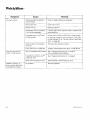
Symptom
Low light output
Cause
Remedy
Filterassemblyon platform
contamrnated.
Cleanor replacefiltersas necessary.
Mirrorsare dirty.
C l e a ntnemrrrors.
Broken
mirrors.
Replaceplatform.
(possible l f a b o v es t e p sf a i l t o i m p r o v eo u t p u t ,r e p l a c ea n d
Misaligned
mirrors
if unitsuffersdamage)
retestplatform.
D a m a g e dM i c r oL i n k @F i b e r
o r f i b e rb u n d l e
F i b e ro r f i b e rb u n d l e
C h e c ke n d so f M i c r oL i n k @
f or damage.Replacewith new Micro Link@Fiber
"Test
#5: Micro Link@Fiber
or fiber bundle.Go to
Test" on page28.
Fiberbundle not connected
correctly.
Be-insertf iber bundlecorrectly.
L a m pn e a re n d o f u s a b l el i f e
F i b e rb u n d l ew i l l n o t
i n s t a liln L i g h tS o u r c e
" clicking
"
Audible
or
arcrng
soundduringthe
process
lampignition
I n s t a lal 2 7 0 W r e p l a c e m e nl at m p ,m o d e l9 0 1 2 5 .
"Operating
N o t a c o m p a t r b lfei b e rb u n d l e S e e
I n s t r u c t i o n so"n p a g e6
U s ec o m p a t i b l b
e u n d l ed e s i g n
"Operatrng
Install/Remove
I n s t r u c t r o n so"n p a g e6
Multi LinkrM
See
ExpansionPort
Multi LinklMExpansionPort
B e m o v eM u l t i L i n k r ME x p a n s i oP
nort
No problem
Normaloperation
W E L C HA L L Y N
CL 300 SURGTGAL
ILLUMTNAToRDrsAssEMBLy
NOTE: Forall tests, remove9 screwsfrom top cover.
N O T E : D o n o t o p e r a t eu n i tw i t h t h e t o p c o v e rr e m o v e df o r m o r et h a n5 m i n u t e so r t h e u n r tw i l l o v e r h e a t .
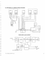
lEsT #1: BLowNFUsEs
T h e p u r p o s eo f t h i st e s t i s t o d e t e r m i n e
t h e s o u r c eo f a s h o r tc i r c u i tc a u s i n gf u s e st o b l o w .R e f e rt o t h e B l o c k
D i a g r a mo n p a g e4 8 .
R e p l a c ea n d r e t e s t h e f u s e s .l f u n i tf u n c t i o n sn o r m a l l yi ,n s p e cftu s e st h a tw e r e b l o w n .l f s o l d e ri s m e l t i n go u t o f
t h e e n d o f t h e f u s ea n dt h e g l a s si s n o t b l a c k e n e dr e
, m o v ea n d r e p l a c et h e p o w e re n t r ym o d u l eT. h i sf a u l to c c u r s
when the prongof the fuse holdermakespoor contactwith the tuse.The prongwill look discoloredand pitted
where it contactsthe fuse.
l f v i s u a il n s p e c t i odno e sn o t y i e l da n ye v i d e n c eo f d a m a g er, e m o v eJ 2 a n dJ 3 f r o m a u x i l i a rbyo a r d( b l u ea n db r o w n
w i r e st h a tc o n n e c tP C B Aa u x ii a r yb o a r dt o t h e p o w e rs u p p l yR
f u s e sa n dt u r n s y s t e mo n . R e m o v ep o w e r
. eplace
a n d i n s p e c ft u s e s
.
l f t h e f u s e sa r e b l o w n ,r e m o v ea n d r e p l a c et h e P C B Aa u x i l i a rbyo a r d( p a r tn o .A 4 - 1 0 6 7 0 ) .
.
l f f u s e sa r et i n e ,r e m o v ea n d r e p l a c et h e p o w e rs u p p t y .
TEsr#2: AuxtLtARyBoARDlNpur TERM|NALS
V e r i t yo p e r a t i n vg o l t a g ei s p r e s e n ot n a u x i l i a rbyo a r di n p u tt e r m r n a l sC. o n n e c m
t e t e ra n ds e t t o v o l t sA C t o J 1 a n d
J 4 t e r m r n a l sW. h e n p o w e ri s a p p l i e dt o t h e u n i tt h e o p e r a t i n vg o l t a g ev, e r i f yi t i s d i s p l a y e od n t h e m e t e r .N O T E :
Verifvthe lamoaccessdoor is closed.
lf voltageis present,replaceand retestauxiliaryboard.
lf voltageis not present,inspectthe fuses,wiring,power entry module,linefilter,and interlockswitch.
N O T E : l f l a m pi s n o t o n a n dv o l t a g ei s p r e s e n tc, h e c ki f t h e p o w e rs u p p l yi s d e f e c t i v e .
lEsr #3: CooUNGFAN
T h e p u r p o s eo f t h i st e s t i s t o v e r i t yt h e o p e r a t i o o
n f t h e l a m pc o o l i n gf a n .
V i s u a l l iyn s p e c ft o r a b r o k e nf a n .W h e nt h e u n i ti s p o w e r e du p , l o o kt o r a f a n n o t t u r n i n g l.f f o u n d ,r e m o v et o p
c o v e ra n d i n s p e cfta n . R e p l a c e
a n yb r o k e nf a n s
'l2VDC
l f f a n i s i n o p e r a t i vaen dn o t b r o k e n m
, e a s u r eu s r n gD M M s e t f o r V o l t sD Cf o r
o n f a n c o n n e c t o r sJ ,l T i s { o r
t h e l a m pf a n ( e x h a u s ta)n dJ 1 0 1 o rt h e p o w e rs u p p l y( i n t a k e ) .
.
lf voltageis present,replaceand retestfan.
.
lf vo tage is not present,replaceand re-testauxilraryboard.
IEST#4: LED OPERATIoN
The purposeof this test is to verifyproperoperationof the LED.
V i s u a l l iyn s p e c t h a tJ 1 i s c o n n e c t e d
t o t h e a u x i l i a rbyo a r d V
. e r i f yc o n t r n u i tovf w i r i n ga n d L E Dw i t h D M M s e t t o
t h e D i o d eS c a l e D
. M M s h o u l dr e a d= . 7 V D C .
P N :L B M A N - C L S E R R
V e v .A
Welc$1yn.
.
l f t h e D M M r e a d i n gd o e sn o t m a t c h ,r e p l a c ea n d r e t e s t h e L E Dh a r n e s s .
.
f D M M r e a d i n gm a t c h e sa b o v e ,r e p l a c ea n d r e t e s t h e a u x i l i a rbyo a r d .
TEST#5: MIcRo LINK@FIBERTEST
The purposeof this test is to verifythe operationof the Micro Link@Fiber.
W i t h t h e i l l u m i n a t oorn , c o n n e c t h e f i b e ra n dt h e h e a d l i g h O
t . v e ra d i s t a n c eo i a t l e a s tf i v ef e e t ,a d j u s t h e s p o t
d i a m e t etro t h e l a r g e sst i z e .
.
l f t h e i n t e n s i t yo f l i g h ti s n o t c o n s i s t e ntth r o u g h o utth e l i g h ts p o ta n dr o t a t i n gt h e d i s t a e
l n d c o n n e c t odr o e s
n o t c a u s et h e s h a p et o c h a n g et,h e h e a d l i g hi ts t h e m o s t l i k e l yc a u s eo Jt h e f a u l t .
.
l f t h e i n t e n s i t yi s n o t c o n s i s t e nwt i t h a l t e r n a t i nlgi g h ta n dd a r kr i n g sa r e p r e s e n tt,h e b r o k e nf i b e ri s b r o k e na t
t h e d r s t ael n d .
O v e rt h e s a m ed i s t a n c ea, d j u s t h e h e a d l i g ht to t h e s m a l l e sdt i a m e t e sr p o t .A t t h i sa d l u s t m e n t h
, e h e a d l i g hits
f o c u s e d l.f a n ys p o t i r r e g u l a r i t i e
a sr e p r e s e n th, o l dt h e h e a d l i g hst t e a d yw h i l er o t a t i n gt h e d i s t a l e n d( b l a c k )
connector.
.
lf the locationof the defectsmove,removethe fiber,cleanthe end with distilledwater,reconnectthe unit,and
test. Replacethe fiber if defectsare still present.
.
lf the locationof the defects remainstationary,
the fault is within the headlight.
WELCHALLYN
ILLUMTNAToR
CL 300 SURGICAL
DrsAssEMBLy
NOTE: All servicingrequiresremovalof the top cover.Removethe 9 screwsand removethe cover.
INTERNAL
MODULE
REMovAL
1 . R e m o v et h e t o p c o v e r .
2 . R e m o v et h e f r o n tb e z e b
l y r e m o v i n gt h e 5 s c r e w ss e c u r i n g
t h e f r o n tb e z e tl o t h e b o t t o mc h a s s i s .
3 . P u l lt h e i n t e r n am
l o d u l eo u t o f t h e p l a t f o r ma s s e m b l y .
4.
Installationis the reverseprocesswith the flat edgeson the gray portionof the internalmodulealignedso rt
l n dt h e b l a c kd o t i n t h e g r a yp l a s t i ct o t h e b o t t o mr i g h t .
w i l l f t i n t ot h e r e c e s s e d
a r e ao f t h e f r o n tp a n e a
PowERSUPPLY
REMovAL
1 . B e m o v et h e t o p c o v e r .
2. Removethe front bezelby removingthe 5 screws securingthe front bezelto the bottom chassis.
3 . R e m o v et h e a i r d u c ts t r a pa n da i r d u c t .
4 . R e m o v et h e 5 w i r e sf r o m t h e P C B Aa u x i l i a rbyo a r d( p a r tn o .A 4 - 1 0 6 7 0 ) .
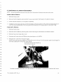
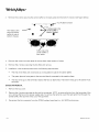
5. Removethe 7 wires f rom the power supply.
NOTEP
: u l lo r p r yt h e w i r e ss t r a i g hut p . R o c k i n g
t h e w i r e t o r e m o v ei t f r o m t h e p o w e rs u p p l ym a yd a m a g et h e
t e r m l n a l ' s o l d e rj o i n to n t h e p o w e rs u p p l yb o a r d .
P u l io r p r yw i r e t e r m i n asl t r a i g hut p .
Do not rockto remove.
U s e b e n tt i Dn e e d l en o s eo l i e r st o o r v t h e t e r m i n aol f f .T h e h a n d l eo f a s c r e w d r i v ei rs u s e da s t h e f u l c r u m .
PN: LB-MAN-CLSERV
ReV.A
TVelc$1*.
6 . R e m o v et h e 4 s c r e w sf r o m t h e p o w e rs u p p l ya n dp u l l t h es u p p l yo u t o f t h e f r o n tt o r e m o v e .
7. Installationis the reverseprocesswith the wires locatedas forrows:
.
P 1 o n p o w e rs u p p l yt o J b o n P C B A( p a r tn o .A 4 - 1 0 6 7 0-)r e dw i r e
.
P 2 A - U s e dt o c o n f r g u r teo 2 3 0 vo p e r a t i o n
o n l y- N O T U S E D
.
P 2 o n p o w e rs u p p l yt o J 4 o n P C B A( p a r rn o .4 4 - 1 0 6 7 0-) b r o w nw i r e
.
P 3 o n p o w e rs u p p l y t o J l o n P C B A( p a r tn o .4 4 1 0 6 7 0 ) b l u e w i r e
.
P4 on power supply- blackwire from red/blackpair- housedin tubing
o
P 5 o n p o w e rs u p p l y- r e d w i r e f r o m r e d / b l a cpka i r- h o u s e di n t u b i n g
.
P 1 1o n p o w e rs u p p l y- r e d o r w h i t e w i r e f r o m r e d / b l a cpka i r( t h t nw i r e p a i r )
.
P12 on power supply- blackwire from red/blackparr(thinwire pair)
PCBA (PARrNo. 44-10670) REMovaL
'1.
Removepower as notedabove.
2. Notthe location
a n d r e m o v ec o n n e c t o rfsr o m J 6 , J 7 , J 9 , J 1 0 ,J 11, a n dJ 1 2 .
3. Usinga short#1 screwdriver,removethe 4 screwsfrom the cornersof PCBA(partno. A4-10670)and remove
PCBA.
4 . I n s t a l l a t i oi sn t h e r e v e r s ep r o c e s sU
. s et h e b l o c kd i a g r a m sa s n e c e s s a rtyo r e c o n n e ctth e w i r e s .S e ef i g u r e
below for properwire routing.
WELCHALLYN
IGNIToR
REMovAL
1 . R e m o v et h e t o p c o v e r .
t e 2 l a m pc a b l ew i r e sa n dt h e r e d a n d b l a c kw i r e sf r o m t h e i g n i t o rN
. o t et h e w i r e l o c a t i o n s .
2 . D i s c o n n e ct h
3. Remove4 screws,securingrgnitormoduleto the centerbaffle.Screwsare locatedon the other side of the
centerbaffle.
4.
Installation
is the reverseprocess.NOTE:becausethe screwdriverwill not directlyreachthe lower screws,
I n s t a l l i nagn dr e m o v i n gt h e s c r e w sl n t ot h e i g n i t o tr o t a p t h e h o l e sp r i o rt o i n s t a l l i ntgh e i g n i t o ri n t h e u n i tw i l l
5 . R e c o n n e ct th e w i r e sa s f o l l o w s{ s e ef i g u r ef o r o r i e n t a t i o n ) .
.
R e dw i r e t o t h e l o w e rc e n t e rm o s tt e r m i n a l .
.
Blackwire to the lower outermosttermina.
- l a m pc a b l ew i r e t o t h e t o p l e f t t e r m i n a(l s h o r t ew
r ire).
+ l a m pc a b l ew i r e t o t h e t o p r i g h tt e r m i n alll o n g e w
r ire).
LINE FILTERREMOVAL
1.
R e m o v et h e t o p c o v e r .
PN: LB MAN CLSERVREv.A
Welc$1ytt'
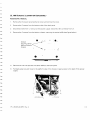
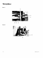
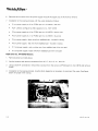
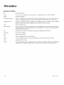
2 . R e m o v et h e s c r e w ss e c u r i n gt h e c e n t e rb a f f l et o t h e b a c kp a n e la n dt h e b o t t o mc h a s s i s( s e ef i g u r eb e l o w ) .
X L SR u b b e rB u m p e r
Hexheadscrew
securingcenter
batfleto sideof
bottomcnassts
a
rentdr baffleto
bottomchassis
a
Screw securing
centerbaffleto
b a c kp a n e l
3. Removethe wires from both ends of the linefilter.Note locationof wires.
4. Removethe 2 screws securingthe linefilter and remove.
5. Installationis the reverseprocesswith the followingrequirements:
.
The end of the filter with 3 terminalsis on the platformside of the centerbaffle.
.
The green (ground)wire goes to the terminaldirectlymountedto the metalsurtace.
.
The bluewires go to the terminalsnearestthe fans on both ends.The brown wires go to the centermost
termrnals.
CHAssrsFANREMovAL
'1
. Removethe top cover.
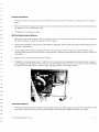
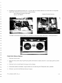
2. Removethe 4 screwssecuringthe fan and the wire guard.NOTE:to removethe fan from the lampside of the
u n i t ,r e m o v et h e f a n o n t h e p o w e rs u p p l ys i d e .T o r e m o v et h e l a m pf a n ,p u s ht h e s p l i tg r o m m e tt h r o u g ht h e
center baffle,then pull the wires out of the grommet.
3. Disconnectthe fan connectorfrom the PCBAAuxiliaryboard(partno. A4-10670)and remove.
WELCHALLYN
4. InstalatlonisthereverseprocesswithJ11forthefanonthelampsrdeandJl0forthefanonthe
s u p p l ys i d e .R o u t et h e w i r e sa s s h o w ni n f i g u r e sb e l o w .
W i r e B o u t i n go n l g n i t o ra n d P C B A
( p a r tn o .4 4 - 1 0 6 7 0 )
C h a s s i sF a nW r r eR o u t i n g
T h el a b eo
l n t h e l a m ps i d ef a n f a c e so u t ,t h e l a b e o
l n t h e p o w e rs u p p l ys i d ef a c e si n ( s e ef i g u r eb e l o w ) .
POWER
ENTRYMoDULEREMoVAL
T . R e m o v et h e t o p c o v e r .
2. Removethe 3 screws securingthe backpanelto the bottom chassisand the 1 screw back panelto center
baffle.
3 . R e m o v et h e 3 w i r e t e r m i n a l sf r o m p o w e re n t r ym o d u l e .
4.
Move backpanelas necessaryto gainaccessto nuts securingthe PEM (powerentry module).
5.
R e m o v en u t sf r o m t h e P E Ma n dr e m o v em o d u l e .
PN: LB-MAN.CLSERV
ReV.A
Welc$11yr..
6. Installation
is the reverseprocesswith the followingrequirements.
.
The lockwasher is insertedbetweenthe PEIV1
and the paintedside of the back panel.
.
The flat washeris insertedbetweenthe non-paintedside of the back paneland the nut.
o
T h e g r e e n( g r o u n dw) i r e i s c o n n e c t e d
t o t h e t e r m i n a l s o l d e r eddi r e c t l yt o t h e m e t a ls u r f a c eT. h e b l u ew i r e
is connectedto the terminallabeledN and the brown wire to the terminalmarkedP
PLATFoRM
REMoVAL
'1
. Removethe top coverand removethe lamp.
2. Removethe front bezelby removingthe 5 screwsthat secureit to the bottom chassis.Removethe internal
mooute.
3. Removethe two screws from the air duct strapand removethe duct.
4. Removethe 4 screws securingthe plat{orm.
5 . R e m o v et h e l a m ps h r o u df r o m t h e p l a t f o r m .
6 . R e m o v et h e p l a t f o r ma n dt h e t h e r m i s t oar s s e m b l yf r o m J 1 2 .
7. Installation
is the reverseprocess.When installingthe platform,verifythat the shroudduct,the strap,andthe
internalmoduleare installed.Reattachthe front bezeland checkfor attenuatorwheel alignment.
.
Botatethe wheel acrossits adjustmentrangeand if the wheel movesfreely,continue,if it does not move
freely,loosenthe platformscrewsand repositionthe platformso the wheel rotatesfreely.
FRoNTBEZELREMoVAL
1. Removethe top cover.
2. Removethe 5 screws, securingthe front bezelto the bottom chassis.
3. Notingthe wire locations,removethe wires from the power switch. Pushout the power switch.
4. Usinga sharpknife,removethe blackRW from the LED.Once removed,applyacetoneto the areabetween
t h e L E Da n dt h e f r o n tp a n e tl o l o o s e nt h e q l u eb o n d .R e m o v et h e L E D .
5. Installationis the reverseprocesswith the LED gluedto the front panelusingLoctite430 or equivalent.Once
s e t ,a p p l yo p a q u es e a l a n tD
, o w C o r n i n g7 3 7 o r e q u i v a l e ntto, t h e a r e aa r o u n dt h e L E Dt o p r e v e n tl i g h tf r o m
t h e i l l u m i n a t opra s s i n gt h r o u g ht h e L E D .
BLowERFANREMovAL
1 . R e m o v et h e t o p c o v e r .
2. Removethe front bezelas describedoreviouslv.
3 . R e m o v et h e a i r d u c t s t r a pa n d d u c ta s d e s c r i b e d
above.
I -34
WELCHALLYN
4 . R e m o v ee l e c t r i c aclo n n e c t oJr g f r o m P C B A( p a r tn o .4 4 - 1 0 6 7 0 ) .
5 . R e m o v et h e 2 n u t s ,s c r e w s ,a n ds p a c e r st h a t m o u n tt h e b l o w e rf a n t o t h e b l o w e rb r a c k e t .
6 . i n s t a l l a t i oi n
s t h e r e v e r s ep r o c e s sw i t h t h e f o l l o w i n gr e q u i r e m e n t s :
.
Spacera
s r ei n s t a l l eo
d n t h e s c r e w sb e t w e e nt h e b r a c k eat n dt h e f a n .
LAMPCABLEREMoVAL
I
R e m o v et h e t o p c o v e r .
2 . O p e nt h e l a m pa c c e s sd o o r ,o p e nt h e l a t c h a
, n dd i s c o n n e ccta b l e .
3 . D i s c o n n e ct h
t e l a m pc a b l ew i r e sf r o m t h e i g n i t o r .
4
P u l ll a m oc d b l eo u t t h r o u g l t-h e l a ' n pa c c e s sd o o r .
5 . I n s t a l l a t i oi sn t h e r e v e r s ep r o c e s sw i t h t h e f o l l o w i n gr e q u i r e m e n t s .
.
B e m o v et h e n y l o nw i r e t i e f r o m t h e l a m pc a b l e .
Feedthe wires throughthe spacebetweenthe linefilter andthe centerchassis.
Connectthe shorterwire to the top left terminalon the ignitor.Connectthe longerwire to the top, right
t e r m i n a lI.n s t a ltlh e t e r m i n a l sb e t w e e nt h e t w o f l a t w a s h e r s( s e ef i g u r ef o r w i r e r o u t i n g ) .
W i r e R o u t i n go n l g n r t oar n d P C B A
( p a r tn o .4 4 - 1 0 6 7 0 )
PN: LB MAN CLSERVRev.A
Welc$11*'
CL 300 SURGTCAL
ILLUMTNAToR
REPATR
PARTSLrsr
Part Number
Description
9 0 12 5
2 7 W RE P L A C E M
tN I LAMP
Photo # Bubble#
'l
t B - M A N - 1 O O W 2 7 O W MANUAL,1OOW2TOWSOLARTEC
A0-10880
LABEL,PROTECTIVE
EARTHGROUND
BETEL27A
TOPCOVER, LENGTHENED
A0-10797
RM-LBL-023
A0-10755
A0-10714
0uantity
'I
1
1
EXTERNAL
MODULEHOLDER,27OW
2
3
S C R E WP
, A I N T E DX, L S
4
Itt
5
1
6
4
7
8
1
101-0033
101-0022
A0-10907
SCREW,
#8 32 X 3/8,PHPS
CHASSIS
BASE
2
2
2
2
10 1 - 0 0 6 8
S E M S ,# 6 - 3 2X 5 / 1 6 ,P H P S
2
9
8
016-0005
X L S ,B U M P E RR, U B B E R5,/ 8
2
10
4
S E M S ,# 6 . 3 2X 9 / 1 6 P H P S
2
11
I
, 2MM
G U A R DF, A N 9
12
13
2
CORD,RETAINING
CLAMP
2
2
F U S E5, A S H E E TI I I
1
A0-10904
B A C KP A N E L
15
213-0019
ROCKEB
SWITCH,
WHITE
ON/OFF,
2
3
3
3
3
3
3
3
3
3
3
4
26
4
27
u 5 0 11 7
u50111
DUCI NOZZLE
BLOWER,
27OW
STRAEAIR DUCT
27OWLAMP SHROUDSUB-ASSEN/
BLY
27OWADJUSTED
POWER
SUPPLY
4
28
4
29
213-0018
S W I T C HI,N T E R L O C K
S,N G LP O L E
4
30
1
1A20012
K E P S#, 6 _ 3 2W
, C O N I C A LW A S H E R
4
31
3
210-0001
L I NE F I L T E R6,. 0 4 , F L A N G E
4
32
I
A0-10768
101,0062
207-0007
105-0008
208-0016
A0-10906
A0- 10905
L A B E LW
, A R N I N GI.L L U M I N A T O F S
S C B E W#, 6 - 3 2X 1 / 4 ,P H S S
BLOWER
BRACI..ET
CENTERBAFFLE
44 10670
PCBAA
, UXILIARY
2 1 80 0 0 3
I G N I T O F2, 7 0 W P I
A0-10864
101-0078
CABLE,
LAMP,3OK
TENSIONWIRE RETAINER
X 1/4,FHD,StT82DG
SCREW,4-40
44-10680
W I R EH A R N E S SL,E D / A U ) ? P S
105-0010
1 1 20 0 0 1
A 0 - 10 8 12
A0-10814
C A B L ET I E ,S M A L L4 "
8
2
16
1
17
1
18
1
19
1
20
21
22
23
1
24
25
1
4
1
1
,l
1
'1
1
,l
WELCHALLYN
PartNumber
Description
Photo# Bubble#
101-0059
S I M S , # 6 - 3 2X 1 i 4 P H P S
4
33
213-0017
P O W E RE N I R YM O D U L E/ L I N EF I L T E R ,
F U SE D
4
34
101-0084
S C R E W#, 6 T H D F R M G ,P H P S
4
35
u50123
u50125
2 7 O WI N T E R N AM
L O D U L ES U BA S S M B
4
27OWFILTER ASSEMBLY
5
36
31
S C R E W#, 4 - 4 0X 1 / 4 ,P H P S
5
38
27OOW
A L I G N E DP L A T F O R M
5
39
S C R E W#, 8 - 3 2X 3 / 4 " , P H P S
5
101-0061
u 5 0 115
101-0073
0uantity
2
4
2
4
6
A4-10672
FAN,BACK,
3 WIRE,27OW
WIREHARN
ESS,FILTEF/GFOUND
44-10673
W I R EH A R NE S S ,S W I T C H / F I L T E R
6
A 4 - 1 Q 647
W I R EH A R NE S S A
, C/FILTER
6
109-0006
B U S H I N GO, P E N E D / C L O S E.D
5O
, O
6
44 10675
W I R EH A R N E S SA,C / S W I T C H
6
46
6
47
1
44-10655
44 10465
W I R E ,P E MT O D I N
41
2
6
44
44-10676
WIRE HARNESS,FILTER/PS
6
48
1
44-10678
W I R EH A R N E S SA,U X T P S
7
AO
1
A4-10677
W I R EH A R NE S S ,O N / O F F / A U X
7
50
1
S E M S ,4 - 4 0X 3 / 8 ,P H P S
7
51
4
44-10683
F A N ,B L O W E RT, E F L O NW I R E
7
52
1
1 0 10 0 8 3
S C E E W4, . 4 0X 1 1 / 4 " , P H P SS, S
7
53
2
1 0 6 - 0 051
S P A C E Rf 4
, U N I h B D , 1 1 4o d , 1 l 4 l
7
54
102-0008
NUT,KEP,4-40, HEX
1
55
2
2
1 0 6 - 0 01
#8
STANDOFF
, ,.751
7
56
4
NUI HEX
8
57
1
WASHER,FLAT
I
58
8
59
1
I
60
2
PLUG,6/25
8
61
1
WASHER,
COLOR
COATED
I
62
1
101-0085
102-0001
104 0007
104 0008
104-0019
101-0038
104-0006
PN: LB-MANCLSERVRev.A
W A S H E RS, E R R A T E D
W A S H L Rt,' 4 E X I L R N A LT O O T F
'I
Velc$11ytr.
PHoro1
PHoro2
9
11
1-3E
WELCHALLYN
PHoTo3
t8
25
17
PHoro4
30 33 32 34
P N :L B - M A NC L S E R VR e v .A
Welc$11ytt*
PHOTo5
PHoro6
WELCHALLYN
PHoro7
PHOTo8
P N :L B - M A NC L S E B VR e VA
.
Velc\Allyn.
GLoSSARY oF TERMS
AC
A l t e r n a t i nC
g urrent
COM
g o m m o nw i r e t e r m r n a t r o n
F o u n do n p o w e rc o n n e c t o r ss,w i t c h e se, t c . . .i n d i c a t i nC
DMM
D i g i t aM
l ultiMeter
F i b e rO p t i cB u n d l e
A n y o f a n u m b e ro f l i g h tt r a n s m i s s i odne v i c e sc h a r a c t e r i z ebdy u s e o f m u l t i p l eh, a i rt h i n
strandsof claddedglassfibers.Usedto deliverlightfrom illuminatorbox to work area.
Leakage
Current
U s u a l l ya s p e c i f i e dm a x i m u ma m o u n t o f a l l o w a b l ec u r r e n tt o p a s s t h r o u g hi s o l a t e d
electricalcomponentswhen subiectedto very high electricalpotentials.
LED
L i g h tE m i t t i n gD i o d e
M e t a lH a l i d e
A n y o f a n u m b e ro f m e t a l l i c o m p o u n d su, s u a l l yi o d i d e st h a ta r e u s e di n t r a c ea m o u n t si n
dischargelight sources.lvletalhalidesare incorporatedto producethe destredspectral
contentot the light source.
NO
N o r m a l l yO p e n ,F o u n do n s w i t c h e si n d i c a t i nngo r m a l l yo p e nt e r m i n a t t o n .
P CB o a r d
P r i n t e dC i r c u i B
t oard
PEM
P o w e rE n t r yM o d u l e
FTV
RoomTemperature
Vulcanizing
Silicone
TRMS
accuracyof digitalmultFmeters.
True Root Mean Squared- usedto characterize
VDC
Voltage-DirectCurrent
Xenon
An elementag
l a s u s e d c o m m o n l yu s e d i n l i g h t i n gp r o d u c t s .U s e d a s a n e v a p o r a n t
s u p p r e s s a ni nt t u n g s t e nh a l o g e nl a m p so r l i g h te m i s s i o ni n g a s e o u sd i s c h a r g lea m p s .
WELCHALLYN
FINAL INSPECTIoN
T h e p u r p o s eo f p r e v e n t a t r vmea r n t e n a n crest o p r o - a c t i v erl ye d u c eo r e l i m i n a t e
f u t u r ep r o b l e m sK. e e p i n g
the light
g
o
o
d
s o u r c ei n
o p e r a t i n cgo n d i t i o n
e n s u r e st h a ti t w i l l p e r f o r mr e l i a b l ay n ds a f e l yE
. v e r ys i xt o t w e l v em o n t h s y, o u
should:
N O T E :P e r f o r mh y p o ta n dg r o u n dc o n t i n u i ttye s t so n t h e u n r tb e f o r eb e g i n n i n tgh e f i n a li n s p e c t i o n .
CL 100SuRGrcAr
ILLUMTNAToR
. h e c kf o r t h e f o l l o w 1 . S e t T I M Et o s t a r t .T u r no n t h e S Y S T E NB
i Ie
. g i nt h e f i f t e e n( 1 5 )m i n u t eB U R N - l Np e r i o dC
ing:
.
D r dt h e y e l l o wL E D l i g h tb r i e f l y ?
.
D i dt h e l a m ps t a r t ?C l i c k i n gb e f o r et h e l a m pi g n i t e sr s n o r m a l( 1 0c l i c k so r l e s s ) .
o
A r e t h e f a n sr u n n i n g ?
2 . A f t e rt h e f i f t e e n( 15 ) m i n u t eb u r n - i ni n s e r t t h eP O W E R T E S T F I B Ei R
n t o t h e P o r t .O p e nt h e a t t e n u a t of ru l l y
a n d m e a s u r et h e l i g h to u t p u t .R o t a t et h e p r o x i m ael n d t o m a x i m i z ep o w e ro u t p u ta n dc h e c kt h e f o l l o w i n g :
.
Doesthe connectorinsertsmoothly?
.
Doesthe attenuatormove smoothly?
.
D o e st h e L r g h tO u t p u tm e a s u r e> 7 5 0 m i l l i w a t t s L
? i g h to u t p u t< 3 7 5 i s c o n s i d e r etdh e e n d o f t h e l i f eo f
the lamp.
.
Turnthe system off and on again3 more times. Does it lightabruptlyand properly?
l f t e s t i n gh a sP A S S E Dc,o n t i n u el.f u n i tf a i l st e s t i n gt,r o u b l e s h o oats n e c e s s a r y .
CL 3OOSURGIcAt
ILLUMINAToR
IMPORTANTClickingbeforethe LAMP ignitesis normal(10 clicksor less).Do not hot re-strikein succession.
( 4 5 )s e c o n d se a c ht i m e b e f o r et u r n i n go f f .
T h e I L L U M I N A T Om
Ru s tr e m a i ni l l u m i n a t efdo r a m i n i m u mo f f o r t y - f i v e
Wait thirty (30)secondsbetween eachre-strike.
T u r nt h e I L L U M I N A T OoRf f a n do n a o a i nt h r e e1 3 )m o r et i m e s .T h e I L L U M I N A T Om
R u s t r e m a i ni l l u m i n a t efdo r a
m i n i m u mo f f o r t y j r v e( 4 5 )s e c o n d se i c h t r m eb e f o r et u r n i n go f f. U s r n ga T I M E R w
, a i tt h i r t y( 3 0 )s e c o n d sb e t w e e n
r e - s t r i k e sC. l r c k i n bg e fo r e t h e L A M Pi g n i t e si s n o r m a (l 1 0c l i c k so r l e s s ) D
. o e si t l i g h tp r o m p t l ya n dp r o p e r l y ?
l f t e s t i n gh a sP A S S E Dc,o n t i n u el.f u n i tf a i l st e s t i n g t, r o u b l e s h o oats n e c e s s a r y .
. h e c kf o r t h e f o l
1 . S e tT I M Et o s t a r t .T u r no n I L L U M I N A T O R
B.e g i nt h e f i f t e e n( 1 5 )m i n u t eB U R N - l Np e r i o dC
lowrng:
.
D i dt h e y e l l o wL E Dl i g h tb r i e lfy ?
.
D i dt h e l a m ps t a r t ?C l i c k i n gb e fo r e t h e l a m pi g n i t e si s n o r m a (l 1 0c l i c k so r l e s s ) .
.
A r e t h e f a n sr u n n i n g ?
PN: LB-MAN-CLSEFV
Rev.A
1-43
Welc\ffi*'
2 . A f t e rt h e f i f t e e n( 1 5 )m i n u t eb u r n - i ni n s e r t h e P O W E RT E S TF I B E Ri n t ot h e P o r t .O p e nt h e a t t e n u a t ofru l l y
a n d m e a s u r et h e l i g h to u t p u t .R o t a t et h e p r o x i m ael n d t o m a x i m i z ep o w e ro u t p u ta n dc h e c kt h e f o l l o w i n g :
.
Doesthe connectorinsertsmoothly?
.
Doesthe attenuatormove smoothly?
.
D o e st h e L r g h tO u t p u tm e a s u r e> 3 6 1 l u m e n s ?L i g h to u t p u t< 2 0 0 i s c o n s i d e r etdh e e n do f t h e l i f eo f t h e
lamp.
WELCHALLYN
SPEcIFIcATIoNS
Physical
x 2 8 6 m m Wx 2 8 6 m m D / 4 . 0 k 9 )
" x 1 1 . 2 5 "D / 9 . 0 1(b1 4 0 m m H
S i z e/ W e i g h t( C L1 0 0 ) 5 . 5 " H x 1 1 . 2 5 W
"
(140mmH
x 2 8 6 m m Wx 3 2 4 m m D / 5 . 0 k 9 )
S l z e/ W e i g h t( C L3 0 0 ) 5 . 5 H x 1 1 . 2 5 " W x 1 2 . 7 5 "D / 11. ' 1 l b
e r o u n dt o p ,b a c ka n ds i d e s
SpaceRequirements M i n i m u m2 " ( 5 1 m m )a i r s p a c a
ne
Paintedsurfaces- polyuretha
F i ni s h
Lamp
'100W
XenonArc
2 7 0 WS h o r tA r c D C M e t a lH a l i d e
LampType
Power Requirements
Electrical
100-240VAC50/60H2
Amperage
2 . 5 A m p s@ 1 2 0 V( S u r g i c al lll u m i n a t oCr L 1 0 0 )
' 1 2 0 V( S u r g i c a l
4 A m p s@
l l l u m i n a t oCr L 3 0 0 )
Salety Compliance
U12601-2
1 n d e d , C S A y ' C A N - C 2N
2 .o2. 6 0 1 - 1 - M 9 0 ,
cD.
6 0 6 0 1 -:' 1 9 9 0A m e n d .2 ,
l E C 6 0 1 -:11 9 8 8 / E N
s ) ,J I ST 1 0 0 1: 1 9 9 2 ,
l E C 6 0 1 - 1 - 2 : 1 9 9 36/0E6N0 1 - 1 - 2 : 1 9( 9C3l a s B
78737
l E C 6 0 12 - 18 : 19 9 6 / E N6 0 6 0 1 - 2 -81: 19 9 6
IECClassification
TypeBF,Classl
lPXO
Operation
Continuous
The CE mark on this productindicatesthat it has beentestedto and conformswith the provisionsnoted
E M Cd i r e c t i v e .
M e d i c aD
l e v i c eD i r e c t i v a
e n d8 9 / 3 3 6 E E C
w i t h i nt h e 9 3 l 4 2 l E E C
y anager
Eu r o p e a nR e g u l a t o rM
EUContact:
W e l c hA l l y nL t d .
C o u n t yM e a t h ,R e p u b l i oc f l r e l a n d
Tel353 46 67700
Fax353 46 27128
P N :L B M A N C L S E B VR C vA
.
Welc$11ytt.
THEoRY oF OPERATToN
LIGHT
SoURcE
T h e L i g h tS o u r c e sc o n s i s o
t f a n e n c l o s u r eh o u s i n ga, h i g hi n t e n s i t yl a m p ,p r o p r i e t a royp t i c apl l a t f o r mu, s e r
i
n
d
i
c
a
t
o
r
s
,
c o n t r o l sa n d
a n da p o w e rs u p p l yw i t h c o n t r oel l e c t r o n i c sC.o o l i n gi s p r o v i d e dv i a i n t e r n af la n s .I n t h e
event that the fan(s)malfunctionsor if adequateair flow is blockedand/orthe internaltemperatureof the device
n echanism
w i l l a u t o m a t i c a lsl yh u to f f
l r o t e c t r om
e x c e e d st h e e n g i n e e r i nsgp e c i f i c a t i o nasn, i n t e r n atlh e r m a p
. f t e rc o o l r n gr,e s t a r t h e L r g h tS o u r c e s .
p o w e rt o t h e r a m p A
REPLAcEMENT
LAMPS
The lampsare high pressure,high intensityand long life Light Sources.They are mountedinto a patentedlamp
l i x t u r ew h i c h i s d e s i g n e dt o a l l o wb o t he a s ya n d r a p i de x c h a n g ei n t h e f i e l da s w e l l a s e n s u r i n gp r e c i s ea | g n m e n t
to the oDticalDlatform.
Powen Suppr-ywrrH CoNTRoLELEcrRoNrcs
All the electricityto the LightSourceis controlledthroughthe ON/OFFswitch. Powerto energizeand operatethe
lamp,fans,and controlcircuitryis providedby a customdesigned,wattageregulated,switchingpower supply.
d y a l a m pv o l t a g em o n i t o r i n cgi r c u i t
T h e o p e r a t i o n al i lf eo f t h e l a m pa n dt h e l a m pl i f ei n d i c a t oar r e c o n t r o l l e b
PoRT
MULT|LtNKn PoRTANDMULT|L|NK* ExpANSroN
Internal,to both the multi LinkrMPort and Multi LinkrMExpansionPort,are patentedcouplingopticsand
mechanicsdesignedto producethe highestoutput powers.Internalto the LightSourcesare fans and heatsinks
d e s i g n e dt o r e d u c et e m p e r a t u r east t h e o p t i c acl o u p l i n g
J o i n t st h e r e b ym i n i m i z i ntgh e p o s s i b i l i toyf d a m a g et o
M i c r oL i n k @F i b e ra n df i b e rb u n d l e s .
1-46
WELCHALLYN
ILLUMTNAToR
CL 100 SURGTCAL
CrRcurr DTAGRAM
POWER
DIAGBAM
SUPPLY
BLOCK
@]4VDC
100240vAc
El\,41
FILTEB
&
FUSE
t--r/
|
I I LAI'/P
I
"\l
LAI\,4P
ATERT
OUTPUT
O.I SHUT
DOWN
INPUT
2 [email protected]
PN:LB MAN CLSERVBCv.A
\Velc\ffi*'
CL 3OOSURGICAL
ILLUMINAToR
CIRCUIT
DIAGRAM
-:
>
E
c a - 3
= i----.*.
148
WELCHALLYN