1
ISBN 978-4-902606-82-9
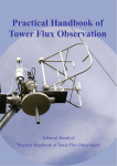
Portable Flux Observation System
User Manual
Forestry and Forest Products Research Institute
Flux Observation Network Edition
森林総合研究所 第2期中期計画成果26(温暖化対策-3)
Contents
1. Overview ............................................................................................................................. 1
2. System Details .................................................................................................................... 3
2.1 Components and Accessories ................................................................................. 3
2.2 Names of Individual Components ........................................................................ 5
2.3 Settings of Individual Components ........................................................................ 8
3. Observation Procedure ...................................................................................................... 11
3.1 Advance Preparation ............................................................................................ 11
3.2 Calibration Procedure........................................................................................... 11
3.3 Instrument Deployment and Connection Procedure............................................. 13
3.4 Data Recording Procedure ................................................................................... 16
3.5 Ending Procedure ............................................................................................... 16
4. System Specifications ....................................................................................................... 17
4.1 Dimensions and Weights ...................................................................................... 17
4.2 Current Consumption ........................................................................................... 17
References Cited ................................................................................................................... 18
Further Reading .................................................................................................................... 18
Acknowledgements ............................................................................................................. 18
Appendices .......................................................................................................................... 19
A1 Method for Checking the Mass Flow Controller Settings .................................. 19
A2 LI-7000 Software Operating Procedure ............................................................... 20
A3 CSAT3 Probe Coordinate System ........................................................................ 21
A4 CR3000 Operating Procedure ............................................................................ 22
A5 CR3000 Control Program ..................................................................................... 23
A6 Parts and Components List ................................................................................... 26
Index ................................................................................................................................... 28
1. Overview ______________________________________________________________________________
1. Overview
As a reference system for tower flux observations, a portable flux observation system which can perform sensible heat,
water vapor, and CO2 flux measurements with the eddy-covariance method was developed.
The inter-site comparison
of tower flux data collected by a variety of measurement systems becomes simplified with the use of this portable flux
observation system as a reference device.
Furthermore, because the portable flux observation system was designed on
the assumption that it would be used for short-term observations, the configuration of the system is simple, and the
principles of operation are easy to understand.
Therefore, the portable flux observation system may serve as a
barebones model of a flux observation system for researchers who intend to initiate new flux observations.
The portable flux observation system consists of a number of components including a closed-path infrared gas
analyzer (LI-7000, LI-COR), an ultrasonic anemo-thermometer (CSAT3, Campbell Scientific), a humidity and
temperature sensor (HMP45A, Vaisala), a data logger which allows high-speed data sampling (CR3000, Campbell
Scientific), and a flow-path control system to be used for calibrations.
a plastic container so that it can be easily carried and deployed.
The portable flux observation system is stored in
All the equipment within the portable flux observation
system can be powered either by 12 V DC or 24 V DC due to the presupposition that the system will be used for
inter-site comparative observations within Asia.
The DC power required for the operation of the system can normally
be obtained by connecting an AC power source to the 100 – 240 V AC input converter included with the system.
Fig. 1 illustrates the flow paths of sampled air and calibration gases through the portable flux observation system.
This is a pressurized system in which the atmospheric air drawn in by a pump upstream of the infrared gas analyzer is
transported into the analyzer.
inlet terminal.
The sampled air drawn in by the pump (P-1) is introduced into the system from the gas
Subsequently, the sampled air passes through the dust filter (DF-1) and is sent to the mass flow
controller (MFC) by way of the solenoid valves (SV-1 and SV-2).
After the flow rate is adjusted by the MFC, the
sampled air passes through another dust filter (DF-2) and is sent into the sample cell of the infrared gas analyzer.
At
other times, the zero and span gases for calibration are introduced from the gas inlet terminals into the system, then to the
flow meters (FM-1 and FM-2, respectively) and to the solenoid valves (SV-1 and SV-2, respectively).
flow path is identical to the flow path for the sampled air.
The subsequent
Regarding the infrared gas analyzer, air from which water
vapor and CO2 have been chemically removed is circulated through the reference cell of the analyzer.
-1-
_____________________________________________________________________________ 1. Overview
Main unit
DF-1
Sampled air
Pump
P-1
NO
NC
Zero gas
SV-1
COM
FM-1
LI-7000 infrared gas analyzer
NO
NC
Span gas
COM
DF-2
SV-2
MFC
Sample cell
FM-2
Exhaust ventilation
Reference cell
DF-3
Pump
Gas inlet terminals
Chemicals for removing
water vapor and CO2
Solenoid valves
(SV-1, SV-2)
Flow meters
(FM-1, FM-2)
Dust filters
(DF-1, DF-2, DF-3)
Mass flow controller
(MFC)
Fig. 1 Flow of sampled air and calibration gases
Fluid flow is directed by the three-way solenoid valves (SV-1 and SV-2).
NO (Normally Open): port which is open when power is off
NC (Normally Closed): port which is closed when power is off
COM (Common): common port which is always open
-2-
2. System Details _________________________________________________________________________
2. System Details
2.1 Components and Accessories
The portable flux observation system consists of a number of components including 1) the main unit which includes
an infrared gas analyzer and a data logger, 2) a power supply unit, 3) an ultrasonic anemo-thermometer, and 4) a
thermo-hygrometer.
The major system components and accessories are summarized in Table 1.
In addition to the
components listed here, use of the system requires calibration gases (zero and span gases), regulators for compressed gas
cylinder, a flat-bladed screwdriver (e.g., 8125 Flat-bladed screwdriver, Campbell Scientific) for connecting wires, and an
adjustable wrench (or a screw wrench) for installing the regulators on the calibration gas cylinders.
(①~⑪) in the table correspond to the numbers in Photo 1.
For the details of other parts and components, refer to
Appendix A6 “Parts and Components List” (→pg. 26).
Table 1 Major system components and accessories
①Main unit
Infrared gas analyzer (LI-7000)
Data logger (CR3000)
Barometer
Mass flow controller
Pump
Flow-path control system
②Power supply unit
Switching power supplies (12 V, 24 V)
③Power cable
Ultrasonic anemo-
④Sensor head (probe and electronics box)
thermometer (CSAT3)
⑤Mounting hardware*
⑥Signal/power cable
Humidity
and
temperature
Sensor (HMP45A)
⑦Ventilation shield
sensor
⑧Signal extension cable
⑨Air sampling inlet
8-6 tube: outer diameter – 8 mm; inner diameter – 6 mm
⑩Tubes
6-4 tube: outer diameter – 6 mm; inner diameter – 4 mm
⑪Compact flash card (CF card)
* The CSAT3 can be mounted on pipes with diameters of 48.5 ~ 50.5 mm with the included
mounting hardware.
If the diameter of the pipe to be used for mounting is outside this range,
mounting equipment other than the one included will be required.
-3-
The numbers
_________________________________________________________________________ 2. System Details
①Main unit
②Power supply unit
Upper left: CSAT3 storage case
Upper right: ④sensor head
Lower: ⑤CSAT3 mounting hardware
Left: ⑥Signal/power cable for CSAT3
Right: Connector on the CSAT3 end
⑧Connectors for the signal cable for the HMP45A
(left: female connector on the extension cable,
right: male connector on the sensor cable)
⑦HMP45A installed in a ventilation shield
⑨Air sampling inlet
③Power cable
⑩Tubes (8-6 tube and 6-4 tube)
⑪ Compact flash card (CF card)
Photo 1 Components and accessories for the portable flux observation system
-4-
2. System Details _________________________________________________________________________
2.2 Names of Individual Components
The names of the individual components installed in the main unit and the power supply unit are shown in Figs. 2 - 4.
Upper Part of the Main Unit
The upper part of the main unit is equipped with a data logger (CR3000), a relay unit for switching solenoid valves, a
barometer, and relay terminal blocks.
CSAT3 cable connection ports
×
1
Data logger CR3000
30
×
×
PTB-100A
#1 - 30
14
1
Barometer
CFM100
#1 - 14
M
L
M
L
#1 - 30
28
U
15
U
CF card slot
#15 - 28
T11
Terminal blocks for signals
CR3000
SAT550-A. –B, -C Signal Cable
#31 - 42
U
M
L
#61 - 80
95
U
81
80
61
Terminal block
T14for HMP45A・AUX
Li7000 Sig-1, -2 Signal Cable
42
31
97
96
T12
Relay
unit
Relay Unit
Diode
Battery
#81 - 95
M
L
Battery
Terminal block for power
supply and solenoid valves
×
×
SV-D, -F
Cable
PW-F, -G
Cable
12V10A
24V1A Cable
×
Power cable for LI-7000
and mass flow controller
T13
Reverse current
prevention circuit
Signal cable for LI-7000
System power cable
Power Cable for
solenoid valves
Fig. 2 Schematic layout of the components installed in the upper part of the main unit
-5-
_________________________________________________________________________ 2. System Details
Lower Part of the Main Unit
The lower part of the main unit is equipped with an infrared gas analyzer (LI-7000), a suction pump for air sampling,
solenoid valves for flow-path control, gas inlets, and a mass flow controller.
Relay terminal block for power supply to the
LI-7000 and the mass flow controller
LI-7000 signal connectors
T21
C24
Li7000
Not Ready
C22
C23
Infrared gas analyzer
LI-7000
Gas inlets
Relay terminal block
for supplying power to
pump
Relay terminal blocks
for LI-7000
Fig. 3 Schematic layout of the components installed in the lower part of the main unit
-6-
Front panel
Power Input
Relay terminal block for
solenoid valves
T23
DC PUMP
T22
Flow meters with
needle valves
Terminal Strip
Left
Right
SV2
C2
Pump
Solenoid
valves
FLOW METER
POWER SUPPLY SOLENOID VALVE
FOR DC PUMP
TERMINAL
Connector for
power cable
LI7000 SIGNAL OUTPUT TERMINAL
SV1
ZERO SPAN
AIR INLET TERMINAL
Air
C3
Tubing/wiring
hole
LI-7000
CO2/H2O ANALYZER
MASS FLOW
CONTROLLER
C21
Power supply
connectors
2. System Details _________________________________________________________________________
Power Supply Unit
The power supply unit supplies power to the main unit after converting the 100 – 240 V commercial power supply into
12 V or 24 V DC.
Fan
12V
DC FAN
24V-output
switchingPower
Switching
power
supply
Supply
-2
12V-output
switching
Switching
Power
power
Supplysupply
-1
HWA050-24
PAA150F-12-N
N
L
G
+12V
GND
N
L
G
GND
+24V
N
L
G
GND
+12V
+24V
GND
T1
× × × × × × × Relay terminal block
× × × × × × × for power supply
--DC output--- -AC inputC1
Fig. 4 Schematic layout of the components installed in the power supply unit
-7-
_________________________________________________________________________ 2. System Details
2.3 Settings of Individual Components
The settings for the individual components of the portable flux observation system are shown below.
Note that
all the components except for the flow-path control system are pre-set, thus, modifications to the settings are
required only for the flow-path control system.
Flow-Path Control System
Table 2 shows the relay unit settings which are used for manually controlling the solenoid valves and the associated
pump.
CAUTION
When introducing calibration gas (setting either OUT channel 1 or OUT channel 2 to “on”),
make sure that OUT channel 5 is set to “off” and the pump is turned off. When controlling
the flow-path via communication from the CR3000, make sure to set all the OUT channels to
“off.”
Table 2 Relay unit settings
OUT channel number
1
2
Solenoid valve 1
Solenoid valve 2
(SV-1)
(SV-2)
Sampled air
OFF
Zero gas
Span gas
Device to be controlled
Channel setting
for gas of
interest
3
4
5
-
-
Pump
OFF
OFF
OFF
ON
ON
OFF
OFF
OFF
OFF
OFF
ON
OFF
OFF
OFF
Mass Flow Controller
Set the mass flow controller to “control mode.” Refer to Appendix A1 “Method for Checking the Mass Flow
Controller Settings” (→pg. 19) for checking and modifying the controlled flow rate.
Table 3 Settings and range of analog output values for the mass flow controller
Variable to be measured
Flow rate
Target flow rate
8.4 L min-1
-8-
Range of possible flow
Corresponding
rate settings
voltage
0 ~ 20 L min-1
0-5 V
2. System Details _________________________________________________________________________
Infrared Gas Analyzer(LI-7000)
The infrared gas analyzer LI-7000 records analog output from the measuring sensors.
Set the analog output ranges to
the default values below.
Table 4 Ranges of analog output values from the LI-7000
Variable to be measured
Corresponding
Output
voltage
channel
0-5 V
DAC1
–100 ~ 900 ppm
0-5 V
DAC2
0 ~ 100 °C
0-5 V
DAC3
70 ~ 120 kPa
0-5 V
DAC4
Range of variable to be measured
Water vapor concentration
CO2 concentration
–10 ~ 40 mmol mol
Temperature in the cell
Pressure in the cell
-1
Ultrasonic Anemo-Thermometer(CSAT3)
The ultrasonic anemo-thermometer CSAT3 outputs data in digital form for recording.
Use the default setting
“AutoRanging” for the output reporting range.
Barometer (PTB-100A) and Humidity and Temperature Sensor (HMP45A)
The settings for analog output value ranges from the barometer and the humidity and temperature sensor are given in
Table 5.
Table 5 Settings of analog output value ranges from the
barometer and the humidity and temperature sensor
Variable to be measured
Pressure within the main unit
Air temperature
Relative humidity
Measuring sensor
Barometer (PTB-100A)
Humidity and temperature
sensor (HMP45A)
Humidity and temperature
sensor (HMP45A)
-9-
Range of
Corresponding
physical quantity
voltage
800 ~ 1060 hPa
0-5 V
-40 ~ 60 °C
0-1 V
0 ~ 100 %
0-1 V
_________________________________________________________________________ 2. System Details
Data Logger (CR3000)
Channel settings for the data logger are given in Table 6.
Table 6 Data logger channel settings
Channel
Input signal (A: analog, D: digital)or channel use
Recording range
1
Unused
-
2
Unused
-
3
Unused
-
4
Unused
-
5
LI-7000 Water vapor concentration (A)
-5~+5 V
6
LI-7000 CO2 concentration (A)
-5~+5 V
7
LI-7000 Temperature in the cell (A)
-5~+5 V
8
LI-7000 Pressure in the cell (A)
-5~+5 V
9
PTB-100A Air pressure in the main unit (A)
-5~+5 V
10
HMP45A Air temperature(A)
-5~+5 V
11
HMP45A Relative humidity (A)
-5~+5 V
12
Flow rate (A)
-5~+5 V
13
Unused
-
14
Unused
-
C1
Solenoid valve port 1 setting (D)
-
C2
Solenoid valve port 2 setting (D)
-
C3
Solenoid valve port 3 setting (D)
-
C4
Solenoid valve port 4 setting (D)
-
C5
Solenoid valve port 5 setting (D)
-
C6
Unused
-
C7
Unused
-
C8
Unused
-
12V
Voltage supply for sensors
-
Shield, power source ground, signal ground
-
SDM-C1
CSAT3 SDM data (D)
-
SDM-C2
CSAT3 SDM clock (D)
-
SDM-C3
CSAT3 SDM enable (D)
-
G
- 10 -
3. Observation Procedure ___________________________________________________________________
3. Observation Procedure
3.1 Advance Preparation
Advance preparation needs to be performed at least 24 hours before the initiation of the observation.
Changing Chemicals in the LI-7000
In order to change the chemicals in the chemical bottles on the back panel of
the LI-7000 within the main unit, remove the bottles from the back panel.
Replace the magnesium perchlorate and CO2 absorbent (sodium hydroxide
coated non-fibrous silicate; trade name: ASCARITE II) in the bottles with fresh
chemicals.
Furthermore, check the record of chemical use and replace the chemicals in
the bottles approximately once a year.
Photo 2 Chemical bottle on
the back panel of an LI-7000
Circulating Air through the LI-7000 Reference Cell
First, apply current to the main unit by connecting it to the power supply unit
with a power cable.
While current is being applied, the green light on the
switching power supply in the power supply unit and the indicator on the mass
flow controller in the main unit will be on.
Subsequently, power up the LI-7000 and circulate air through the reference
cell for 24 hours or longer to remove CO2 and water vapor from the cell.
Calibrating the LI-7000
If calibration gas cylinders such as zero-gas and span-gas cylinders cannot be
Photo 3 Chemicals used
during LI-7000 operation
Left: ASCARITE II
Center: Magnesium perchlorate
Right: A chemical bottle which
has been removed from an
LI-7000
provided at the observation site, the LI-7000 needs to be calibrated before the
portable flux observation system is transported to the site.
Refer to the
following section, Section 3.2 “Calibration Procedure” for details.
Charging the Battery of the CR3000
Charge the battery of the CR3000 as necessary.
3.2 Calibration Procedure
For the calibration of the LI-7000, use the LI-7000 software which is distributed on the LI-COR website:
http://www.licor.com/env/products/gas_analyzers/LI-7000/LI-7000_software.jsp
Preparing the Calibration Gas Cylinders
①
Attach a regulator to each of the calibration gas cylinders, i.e., the zero- and span-gas (air balance) cylinders.
- 11 -
__________________________________________________________________ 3. Observation Procedure
Connecting the LI-7000 to a PC and Starting the LI-7000 Software
②
Connect the LI-7000 to a PC with a USB cable.
③
Power up the LI-7000.
④
Start the LI-7000 software on the PC.
Performing Zero Calibration
⑤
Connect the regulator for the zero-gas cylinder to the gas inlet, ZERO GAS
terminal, located in the lower part of the main unit, using a 6-4 tube (outer
diameter: 6mm, inner diameter: 4mm).
CAUTION
Open the cylinder valve a little and use the regulator to adjust the
secondary pressure of the zero gas to a sufficiently low value (approx.
ON
OFF
OFF
OFF
OFF
0.05 MPa) so that excess loading on the tubing system can be avoided.
⑥
Set only OUT Channel 1 on the relay unit to “on” (refer to Photo 4).
⑦
Use the needle valve on the flow meter to adjust the flow rate to
Photo 4 Settings for relay
unit. (Only OUT channel 1
is on.)
approximately 1.0 L min-1 while checking the display on the mass flow
controller (refer to Photos 5 and 6).
⑧
Perform zero calibration after the concentration reading from the LI-7000
software stabilizes, which usually takes approximately 5 minutes after the
initiation of the gas flow. For the software operating procedure relevant
for this step, refer to Appendix A2 “LI-7000 Software Operating Procedure:
Performing Zero Calibration” (→pg. 20).
Photo 5 Mass flow controller
Performing Span Calibration
⑨
Connect the regulator for the span-gas cylinder to the gas inlet, SPAN GAS
terminal, located in the lower part of the main unit, using a 6-4 tube.
CAUTION
Open the cylinder valve a little and use the regulator to adjust the
secondary pressure of the zero gas to a sufficiently low value (approx.
0.05 MPa) so that excess loading on the tubing system can be avoided.
Photo 6 Flow meters with
needle valves ( ○ needle
valves)
⑩
Set only OUT Channel 2 on the relay unit to “on”.
⑪
Use the needle valve on the flow meter to adjust the flow rate to approximately 1.0 L min-1 while checking the
display on the mass flow controller (refer to Photos 5 and 6).
⑫
Perform span calibration after the concentration reading from the LI-7000 software stabilizes, which usually takes
approximately 5 minutes after the initiation of gas flow.
For the software operating procedure relevant for this step,
refer to Appendix A2 “LI-7000 Software Operating Procedure: Performing Span Calibration” (→pg. 20).
- 12 -
3. Observation Procedure ___________________________________________________________________
Ending Calibration
⑬
Exit the LI-7000 software.
For the software operating procedure relevant for this step, refer to Appendix A2
“LI-7000 Software Operating Procedure: Shutting Down the Software” (→pg. 20).
⑭
Set all the OUT channels on the relay unit back to “off.”
⑮
Close all regulator valves before removing the tubes.
3.3 Instrument Deployment and Connection Procedure
Tubes and cables are to be arranged as described in the following procedure.
Tubing and cabling layouts are shown in Fig. 5 (→ pg. 15).
Deploying the Instruments
①
Deploy the ultrasonic anemo-thermometer (CSAT3).
For the probe
coordinate system, refer to Appendix A3 “CSAT3 Probe Coordinate
Photo 7 Example of air
sampling inlet deployment
System” (→pg. 21).
②
Install the air sampling inlet near a CSAT3 arm (refer to Photo 7) and
connect an 8-6 tube (outer diameter: 8 mm, inner diameter: 6 mm) to the air
sampling inlet.
③
Deploy the humidity and temperature sensor (HMP45A) at the same height
as the CSAT3 probe.
Wiring Signal Cables and Installing the Air Sampling Inlet Tube
④
Insert the CSAT3 cable through the tubing/wiring hole in the main unit and
Photo 8 Tubing/wiring hole
viewed from inside the
main unit (←tubing/wiring
hole)
connect the cable to the lowest row of terminals on the data logger
(CR3000) (refer to Photo 8 and Table 7 on the next page).
⑤
Insert the tube (8-6 tube) connected to the air sampling inlet through the
tubing/wiring hole in the main unit and connect the tube to the tube
diameter conversion adapter attached to the Air terminal at the gas inlets
(refer to Photo 9).
⑥
Insert the HPM45A signal cable through the tubing/wiring hole in the main
unit.
Connect the humidity and temperature sensor to the HMP45·AUX
terminal block using the signal cable (refer to Table 8 on the next page).
Photo 9 Gas inlets
A tube diameter conversion
adaptor is attached to the Air
terminal on the left.
Connecting Calibration Gas Tubes (for the Case of Automated Calibration)
⑦
If automated calibration is performed during the observation, insert the tubes for the calibration gases (zero and
span gases) through the tubing/wiring hole in the main unit and connect the tubes to the ZERO GAS and SPAN
GAS terminals at the gas inlets.
- 13 -
__________________________________________________________________ 3. Observation Procedure
Starting Up the System
⑧
Connect the main and power supply units with a power cable.
⑨
Start the portable flux observation system after connecting the power supply unit cable to the power source.
Table 7 CSAT3 cable connection points
Table 8 HMP45A signal cable connection points
(The lowest row of CR3000 terminals)
(HMP45A・AUX terminal block)
Power cable
Signal cable
Cable color
Terminal label
Cable color
Terminal label
red
12V
red
Ta+
black
G
transparent
G
brown
Rh+
green
SDM1
yellow
Rh-
white
SDM2
blue
Pw +V
brown
SDM3
orange
Pw GND
black
G
white
FAN +V
transparent
G
black
FAN GND
-
- 14 -
(Ta- and Rh- are combined)
3. Observation Procedure ___________________________________________________________________
Humidity and
temperature sensor
HMP45A
Main Unit
HMP45A signal cable
×
1
30
×
×
PTB-100A
#1 - 30
14
1
Ultrasonic thermo-anemomter
CSAT3
CFM100
#1 - 14
M
L
M
L
#1 - 30
28
U
15
U
#15 - 28
T11
CR3000
CSAT3 signal/
power cable
U
M
L
#61 - 80
95
81
80
61
T14
U
Li7000 Sig-1, -2 Signal Cable
#31 - 42
SAT550-A. –B, -C Signal Cable
Air sampling
inlet tube (8-6)
T12
42
31
97
96
Air sampling inlet
Relay Unit
Diode
#81 - 95
M
L
SV-D, -F
Cable
Battery
T21
C23
Front panel
Terminal Strip
Left
Right
SV2
T23
Power Input
DC PUMP
FLOW METER
POWER SUPPLY SOLENOID VALVE
FOR DC PUMP
TERMINAL
C2
LI7000 SIGNAL OUTPUT TERMINAL
SV1
ZERO SPAN
AIR INLET TERMINAL
Air
C3
6-4 tube
6-4 tube
N
L
G
+12V
GND
PAA150F-12-N
Switching Power
Supply - 1
GND
N
L
G
GND
+24V
Switching Power
Supply - 2
12V DC FAN
HWA050-24
+24V
+12V
GND
G
L
N
× × × × × × ×
× × × × × × ×
--DC output--- -AC input-
C1
Z
e
r
o
LI-7000
CO2/H2O ANALYZER
C21
MASS FLOW
CONTROLLER
T22
Power supply unit
Li7000
Not Ready
C22
C24
×
×
PW-F, -G
Cable
12V10A
24V1A Cable
×
Power cable
T13
S
p
a
n
USB cable
PC
Calibration
gases
*The dashed lines are connections to
be made during calibration
Fig. 5 Schematic of tubing and cabling layouts
- 15 -
__________________________________________________________________ 3. Observation Procedure
3.4 Data Recording Procedure
①
Perform calibration prior to the initiation of the measurements.
For details,
refer to Section 3.2 “Calibration Procedure” (→ pg. 11).
②
Make sure that all the OUT channels on the relay unit are set to “off.”
③
Connect the CR3000 power connector to the CR3000 data logger to turn on
the data logger (refer to Photo 10).
④
Insert the CF card into the card slot (CF card module) on the CR3000 data
logger.
⑤
When comparative flux observations are performed, check the clock on the
Photo 10 CR3000
power connector
CR3000 and set it so that it matches the time on the observation system to
be compared against.
⑥
Using the control panel, check to make sure that “Run on Power Up” (for automated recovery after a power
outage) and “Run Now” on the CR3000 are activated.
recording.
Subsequently, execute the control program to start data
For the operating procedure relevant for this step, refer to Appendix A4 “CR3000 Operating
Procedure: Program Execution Procedure” (→pg. 22).
The source code for the control program is shown in
Appendix A5 “CR3000 Control Program” (→pg. 23).
⑦
During continuous observations, deploy the main unit in the shade and keep the cover closed to avoid increased
temperatures in the interior of the system.
(If the main unit is deployed indoors, the cover of the main unit can be
left open for heat release.)
3.5 Ending Procedure
①
Press the white removal button on the CF card module and wait for the
status LED to turn from red to green.
Within the subsequent 20 seconds,
open up the cover of the CF card module and remove the CF card (refer to
Photo 11).
CAUTION
If the user continues on to the next step in the ending procedure without
removing the CF card, the recorded data will not be saved, thus, caution
Photo 11 Removal button
(→) and status LED (→)
is necessary.
②
After confirming the removal of the CF card, shut down the CR3000 using the control panel.
For this procedure,
refer to Appendix A4 “CR3000 Operating Procedure: Program Termination Procedure” (→pg. 22).
③
Power down the portable flux observation system by unplugging the CR3000 power connector and the power
supply unit.
- 16 -
4. System Specifications ____________________________________________________________________
4. System Specifications
4.1 Dimensions and Weights
Table 7 Dimensions and weights of system components
Dimensions
Weight
Main unit
W826 × H521 × D287 mm
37.66 kg
Power supply unit
W371 × H258 × D152 mm
6.70 kg
Power cable
L5.4 m
1.56 kg
CSAT3 carrying case (including the sensor head)
W700 × H680 × D320 mm
CSAT3 signal/power cable
L50 m × 2 cables
3.67 kg
Ventilated shield (HMP45A, including mounting hardware)
W760 × H220 × D220 mm
3.77 kg
HMP45A signal cable
L50 m
5.49 kg
6-4 tube (outer diameter: 6 mm, inner diameter: 4 mm)
L15 m × 2 tubes
0.67 kg
8-6 tube (outer diameter: 8 mm, inner diameter: 6mm)
L40 m
1.99 kg
Total weight
16.47 kg
Approx. 78 kg
4.2 Current Consumption
Table 8 Current consumption of the system components
Infrared gas analyzer LI-7000 (LI-COR)
Pump MVP03V12BA2 (Panasonic)
Mass flow controller CMQ0020 (Yamatake)
Main unit
Solenoid valve AG31-02-2 (CKD)
Data logger CR3000 (Campbell Scientific)
Barometer PTB-100A (Vaisala)
Ultrasonic anemo-thermometer CSAT3
(Campbell Scientific)
shield
Supply voltage
4A max.
DC10.5-16 V
2.5A
DC8-15 V
300mA max.
DC15-24 V
920mA
*main unit is equipped with two solenoid valves
Ventilation
Current consumption
Humidity and temperature sensor HMP45A (Vaisala)
Fan RD804A (Prince Fan)
Total current consumption
(per valve)
10mA
DC10-16 V
4mA max.
DC10-30 V
200mA
DC10-16 V
4mA max.
DC7-35 V
170mA
DC12 V
9A max.
- 17 -
DC12 V
______________________________________________________________________________ References
References Cited
LI-COR, "LI-7000 CO2/H2O Analyzer Instruction Manual",
ftp://ftp.licor.com/perm/env/LI-7000/Manual/LI-7000Manual.pdf
Campbell Scientific, Inc., "CR3000 Micrologger Operator's Manual", Revision 5/10,
http://www.campbellsci.com/documents/manuals/cr3000.pdf
Campbell Scientific, Inc., "CSAT3 Three Dimensional Sonic Anemometer Instruction Manual", Revision: 6/10,
http://www.campbellsci.com/documents/manuals/csat3.pdf
Further Reading
Editorial Board of Practical Handbook of Tower Flux Observation: “Practical Handbook of Tower Flux Observation”
http://www2.ffpri.affrc.go.jp/labs/flux/manual/manual_index_e.html
OHTANI Yoshikazu, MIZOGUCHI Yasuko, TAKANASHI Satoru, YASUDA Yukio, IWATA Hiroki, NAKAI Yuichiro,
YUTA Satoko, YAMANOI Katsumi (2010): Development of a portable CO2 flux observation system using a
closed-path gas analyzer for intercomparison. Bulletin of the Forestry and Forest Products Research Institute,
9(1):31-36, http://www.ffpri.affrc.go.jp/pubs/bulletin/414/documents/414-3.pdf
Acknowledgements
We wish to acknowledge Yukio YASUDA of the Tohoku Research Center, Forestry and Forest Products Research
Institute for his cooperation on the development of the portable flux observation system. We also wish to thank Hiroki
IWATA of the International Arctic Research Center of the University of Alaska for his assistance with building the
system.
A part of the production of this manual as well as the development and production of the portable flux observation
system were partially funded by 1) the Special Coordination Funds for Promoting Science and Technology of the
Ministry of Education, Culture, Sports, Science and Technology, “Standardization and systematization of carbon-budget
observation in Asian terrestrial ecosystem based on AsiaFlux network” and 2) Global Environment Research Account for
National Institutes of the Ministry of the Environment, “Long-term Monitoring of Carbon Flux and Promotion of a Data
Network in Asian Terrestrial Ecosystems.”
- 18 -
Appendices ______________________________________________________________________________
Appendices
A1 Method for Checking the Mass Flow Controller Settings
Checking the Operating Mode
If the operating mode of the mass flow controller is properly set to “control mode”, the OK light on the upper surface
of the mass flow controller will be on.
If the OK light is off, the flow rate is not yet stable.
while and confirm that the light has turned on.
In this case, wait for a
(If the OK light is blinking or the seven-segment display shows “off,”
refer to the instruction manual for the mass flow controller and reset the operating mode.)
Checking the Controlled Flow Rate
When the [DISP] button on the upper surface of the mass flow controller is pressed, the SP light will turn on and the
current setting of the controlled flow rate will be displayed.
To modify the controlled flow rate, press either the [▵] or
[▿] button to change the numerical value and then press the [ENT] button.
This procedure needs to be performed while
the SP light is on.
For the details of operating the mass flow controller, refer to the instruction manuals for the digital mass flow
controller CMQ series manufactured by Yamatake Corporation.
The manuals which can currently be viewed online are
those for the succeeding models in the “digital mass flow controller CMQ-V series,” however, the procedures for
checking the operating mode and for checking and modifying the controlled flow rate are the same as those for the CMQ
series.
http://www.compoclub.com/products/recommend/mf/mf_mqv1.html
(the instruction manuals are available in Japanese only).
- 19 -
______________________________________________________________________________Appendices
A2 LI-7000 Software Operating Procedure
Performing Zero Calibration
①
[LI-7000] main window: from the [Remote] menu, select [Connect].
②
[Connect to LI-7000] dialogue: click on the USB tab (confirm that
SN:IRG4-0517 is displayed).
Select [Use Instrument Configuration] and
click the [Connect] button.
③
[LI-7000] main window: the measured values are displayed.
④
[LI-7000] main window: from the [Remote] menu, select [User
Calibration].
⑤
[User Calibration] dialogue: first, perform H2O calibration.
From the
[H2O Action] drop-down menu, select [Make cell B match cell A] and click
the [Do H2O Cal] button.
⑥
[User Calibration] dialogue: next, perform CO2 calibration.
From the
[CO2 Action] drop-down menu, select [Make cell B match cell A] and click
the [Do CO2 Cal] button.
Performing Span Calibration
①~④ Same as for zero calibration
⑤
[User Calibration] dialogue: perform CO2 calibration.
From the [CO2
Fig. A1 LI-7000 software
windows (zero calibration)
Action] drop-down menu, select [Make cell B read…], enter the reference
concentration, and click the [Do CO2 Cal] button.
Shutting Down the Software
①
[LI-7000] main window: from the [Remote] menu, select [Disconnect].
②
[LI-7000] main window: from the [File] menu, select [Exit].
Fig. A2 LI-7000 software
window (span calibration)
For details, refer to the LI-7000 Instruction Manual.
(ftp://ftp.licor.com/perm/env/LI-7000/Manual/LI-7000Manual.pdf)
- 20 -
Appendices ______________________________________________________________________________
A3 CSAT3 Probe Coordinate System
Back side of sensor
CSAT3
Front side of sensor
Z
X
Y
Fig. A3 CSAT3 probe coordinate system
The arrows in the figure show the directions of wind vectors.
For the X-axis, a positive value is output for wind which
flows from the front side of the sensor (the right side in the figure above) toward the sensor.
For the Y-axis, a positive
value is output for wind which flows from left to right when the front side of the sensor is viewed from the back side of
the sensor, i.e. from the back of the page to the front of the page in the figure above.
output for wind which flows upward in the vertical direction.
- 21 -
For the Z-axis, a positive value is
______________________________________________________________________________Appendices
A4 CR3000 Operating Procedure
Program Execution Procedure
①
Make sure that no programs are being executed on the CR3000.
Display
the main menu by pressing any button other than [◁], [▷], [▵], or [ESC].
②
Move the cursor to [Run/Stop Program] by pressing either the [▵] or [▿]
button, and display the program list by pressing the [Enter] button.
③
Select the name of the program to be executed (the name of the program
loaded
on
the
present
flux
observation
system
is
“PORTABLE_CSAT3SDM.CR”) by pressing either the [▵] or [▿] button.
Press the [Enter] button.
④
The option menu will now be displayed.
Select the [Run on Power Up] option by pressing either the [▵] or [▿] button,
and press the [Enter] button to display a * to the left of this option name
(with this operation, the selected option becomes activated).
Fig. A4 Control panel on
the CR3000
Repeat the
procedure to activate the [Run Now] option.
⑤
Move the cursor to [Execute] which is located at the bottom of the list, and press the [Enter] button.
⑥
When the message confirming the intention to execute the program is displayed, execute the program by selecting
[Yes] and pressing the [Enter] button.
Program Termination Procedure
①
While a program is being executed on the CR3000, display the main menu by pressing any button on the control
panel other than [◁], [▷], [▵], or [ESC].
②
Move the cursor to [Run/Stop Program] by pressing either the [▵] or [▿] button. Press the [Enter] button. The
option menu will now be displayed.
③
Select the [Stop, Retain Data] option by pressing either the [▵] or [▿] button, and press the [Enter] button to display
a * to the left of this option name (with this operation, the selected option becomes activated).
④
Move the cursor to [Execute] which is located at the bottom of the list, and press the [Enter] button.
⑤
When the message confirming the intention to terminate the program is displayed, terminate the program by
selecting [Yes] and pressing the [Enter] button.
For details of operating the CR3000, refer to the CR3000 Operator’s Manual.
(http://www.campbellsci.com/documents/manuals/cr3000.pdf)
- 22 -
Appendices ______________________________________________________________________________
A5 CR3000 Control Program
The program loaded on the present flux observation system, PORTABLE_CSAT3SDM.CR, controls the following
three processes.
1.
Sampling and recording data at 10 Hz.
2.
Performing switchover of the solenoid valves and the pump for introducing calibration gases at the following
times each day.
3.
23:39
Stop the measurements (turn off the pump)
23:40
Introduce the zero gas
23:45
Turn off the zero gas and introduce the span gas
23:50
Turn off the span gas and turn on the pump
Outputting data to the memory card and writing reference data (physical quantities) to the internal memory (for
checking the real-time data)
Output to Memory Card
Table A1 Data output to memory card
Column
Output data
Unit
1
X-direction wind speed, X
m s -1
2
Y-direction wind speed, Y
m s -1
3
Z-direction wind speed, Z
m s -1
4
Air temperature, T (CSAT3 measurement value)
°C
5
Water vapor concentration, H2O
mV
Analog voltage values
6
CO2 concentration, CO2
mV
(0~5 V max.)
7
Temperature in the cell, Ti
mV
8
Pressure in the cell, Pi
mV
9
Air pressure in the main unit, Pa
mV
10
Air temperature, Ta
mV
11
Relative humidity, RH
mV
12
Flow rate, Flow
mV
13-14
Unused
Source Code of the Program
1
2
3
4
5
6
7
8
9
Form of output
'CR3000 Series Datalogger with CSAT3-SDM
'date: 2010-04-02
'program author: Takanashi, S. (For. Met. Lab., FFPRI)
'Declare Constants
Const StopMeasureMinutes = 1419
'23:39
Const StartZeroMinutes
= 1420
'23:40
Const StartSpanMinutes
= StartZeroMinutes+5
'23:45
Const StartMeasureMinutes = StartSpanMinutes+5
'23:50
Const FileMarkMinutes
= StartMeasureMinutes+5 '23:55
- 23 -
Physical quantities
______________________________________________________________________________Appendices
10
11
12
13
14
15
16
17
18
19
20
21
22
23
24
25
26
27
28
29
30
31
32
33
34
35
36
37
38
39
40
41
42
43
44
45
46
47
48
49
50
51
52
53
54
55
56
57
58
59
60
61
62
Const Interval = 100 ' msec
Const DataLapse = 0 ' 0:every blank data will be timestamped
Const DataIntegration = 250 '250, _60Hz, _50Hz
Const VoltRange = mV5000
Const DataMax = 14
Const SDM_PER = 50
'Declare Public Variables
Public Diffch(DataMax)
Public IRGAData(4)
Public SATData(6)
Public TARHData(2)
Public OIRGAData(4)
Public Ptemp
Public Flow
'Define Data Tables
DataTable(FluxData,1,-1)
DataInterval(0,Interval,msec,DataLapse)
CardOut(1,-1)'CardOut(0:Ring 1:FillandStop, -1:Auto-allocate n:Size)
Sample(DataMax,Diffch(1),IEEE4)
FieldNames("X:m/s,Y:m/s,Z:m/s,T:degC,H2O:mv,CO2:mv,Ti:mv,Pi:mv,Pa:mv,Ta:mv,RH:mv,Flow:mv,AUX2
:mv,AUX3:mv")
EndTable
DataTable(IRGA,1,600)
Sample(4,IRGAData(1),IEEE4)
FieldNames("H2O:mmol/mol,CO2:ppm,Ti:degC,Pi:kPa")
EndTable
DataTable(SAT,1,600)
Sample(4,SATData(1),IEEE4)
FieldNames("X:m/s,Y:m/s,Z:m/s,T:degC")
EndTable
DataTable(VAISALA,1,600)
Sample(1,Diffch(4),IEEE4)
FieldNames("SATa_T:degC")
Sample(1,SATData(4),IEEE4)
FieldNames("SATd_T:degC")
Sample(2,TARHData(1),IEEE4)
FieldNames("HMP45A_T:degC,HMP45A_RH:%")
Sample(1,Ptemp,IEEE4)
FieldNames("PTemp:degC")
EndTable
DataTable(Flow,1,600)
Sample(1,Flow,IEEE4)
FieldNames("Flow:l/s")
EndTable
'Define Subroutines
Sub ZeroCalibration
PortSet(1,1)
PortSet(2,0)
PortSet(3,1)
PortSet(4,1)
PortSet(5,0)
EndSub
Sub SpanCalibration
PortSet(1,0)
- 24 -
Appendices ______________________________________________________________________________
63
64
65
66
67
68
69
70
71
72
73
74
75
76
77
78
79
80
81
82
83
84
85
86
87
88
89
90
91
92
93
94
95
96
97
98
99
100
101
102
103
104
105
106
107
PortSet(2,1)
PortSet(3,1)
PortSet(4,1)
PortSet(5,0)
EndSub
Sub StartMeasure
PortSet(1,0)
PortSet(2,0)
PortSet(3,0)
PortSet(4,0)
PortSet(5,1)
EndSub
'Main Program
BeginProg
Call StartMeasure
SDMSpeed (SDM_PER) 'The resolution of the bit period is 1 uSec.
Scan(Interval,msec,600,0)
'VoltDiff(Dest,Reps,Range,Diffchan,RevDiff,Settlingtime,Integ,Mult,Offset)
VoltDiff(Diffch(5),10,VoltRange,5,0,0,DataIntegration,1,0)
'Set SDM bit period and get data from the CSAT3.
CSAT3 (SATData(1),1,3,91,60) 'SDM address 3.
Diffch(1)=SATData(1)
Diffch(2)=SATData(2)
Diffch(3)=SATData(3)
Diffch(4)=SATData(4)
IRGAData(1)=0.01*Diffch(5)-10
IRGAData(2)=0.2*Diffch(6)-100
IRGAData(3)=0.02*Diffch(7)
IRGAData(4)=0.01*Diffch(8)+70
TARHData(1)=Diffch(10)*0.1-40
TARHData(2)=Diffch(11)*0.1
Flow=Diffch(12)*0.004
PanelTemp (Ptemp,250)
If TimeIntoInterval(1320,1440,min) Then Call StartMeasure
If TimeIntoInterval(StopMeasureMinutes,1440,min) Then Call EndMeasure
If TimeIntoInterval(StartZeroMinutes,1440,min) Then Call ZeroCalibration
If TimeIntoInterval(StartSpanMinutes,1440,min) Then Call SpanCalibration
If TimeIntoInterval(StartMeasureMinutes,1440,min) Then Call StartMeasure
CallTable IRGA
CallTable SAT
CallTable FluxData
CallTable VAISALA
CallTable Flow
NextScan
EndProg
- 25 -
______________________________________________________________________________Appendices
A6 Parts and Components List
Main Unit
1. MASS FLOW CONTROLLER (MFC)
MFC
CMQ series (YAMATAKE, Japan)
CMQ0020BSSN000000.
20 L min-1 full scale (FS) (control range :1 to 100% FS)
Working voltage: 24 V DC
2. SOLENOID VALVE
SV-1, SV-2
AG31-02-2-03A-DC12V (CKD, Japan)
Working voltage: 12 V DC
3. FLOW METER
FM-1, FM-2
RK1650 (KOFLOC, Japan)
5 L min-1 FS
4. DUST FILTERS
DF-1
Balston Disposable Air Filter #300-01961 (available from LI-COR, U.S.A)
DF-2, DF-3
Gelman Acro 50, #9967-008 (available from LI-COR, U.S.A) 1.0μm, PTFE
5. ELECTRIC TERMINALS
280-681 (terminal) (WAGO, Japan)
280-326 (end plate for 280-681) (WAGO, Japan)
280-907 (common earth terminal) (WAGO, Japan)
280-309 (end plate for 280-907) (WAGO, Japan)
249-116 (end stop) (WAGO, Japan)
209-666 (number plate) (WAGO, Japan)
209-607 (number plate) (WAGO, Japan)
DIN Rail (50 cm length, Aluminum)
Gap arrester Y08U-75B (Sankosha, Japan)
6. ELECTRIC CONNECTORS
8-pin panel mount: female MMS3102A-22-23-S (MISUMI, Japan)
8-pin straight: male MMS3106B-22-23-P (MISUMI, Japan)
7-pin panel mount: female MMS3102A-20-15-S (MISUMI, Japan)
7-pin straight: male MMS3106B-20-15-P (MISUMI, Japan)
Dust cap NMS25042-20D (MISUMI, Japan)
Dust cap NMS25043-20D (MISUMI, Japan)
Cable clamp NMS3057-12A (MISUMI, Japan)
- 26 -
Appendices ______________________________________________________________________________
7. TUBE
For the pump-filter segment: NRK Unitube (Nippon Rikagaku Kikai)
#7SW 7×13
6-4 tube: polyethylene
8-6 tube: PTFE
8. TUBE FITTINGS
PU6 (straight) (PISCO)
PG8-6 (straight, different diameters on ends) (PISCO)
PM6 (bulkhead) (PISCO)
SS-6M0-1-4RT (straight) (Swagelok)
SS-6M0-7-4RT (straight) (Swagelok)
SS-6M0-2-4RT (90deg elbow) (Swagelok)
9. CARRY CASE
Pelican Box
#1650 (PELICAN, USA)
10. PUMP
MVP03V12BA1 (Panasonic, Japan)
30 L min-1
Working voltage: 12 V DC
Power Supply Unit
1. SWITCHING POWER SUPPLY
PAA150F-12-N (COSEL, Japan)
Input: 85 to 264 V AC, Output: 12 V DC 13A
Working voltage: 100-240 AC
HWA050-24 (SANKEN, Japan)
Input: 85 to 264 V AC, Output: 24 V DC 2.1A
Working voltage: 100-240 AC
2. FAN
CF-50SS (ADDA, China)
50 mm, 3700 rpm ± 10 %
Working voltage: 12 V DC
3. CARRY CASE
Pelican Box
#1450 (PELICAN, USA)
- 27 -
___________________________________________________________________________________ Index
Index
—1~9—
—M—
6-4 tube.................................................... 3, 4, 12, 15, 17, 27
main unit ................................................................................
8-6 tube.................................................... 3, 4, 13, 15, 17, 27
................... 3, 4, 5, 6, 7, 9, 10, 11, 12, 13, 15, 16, 17, 23, 26
—A—
mass flow controller (MFC)....... 1, 3, 6, 8, 11, 12, 17, 19, 26
air sampling inlet ................................................. 3, 4, 13, 15
—N—
automated calibration ........................................................ 13
needle valve ................................................................... 6, 12
—C—
—O—
calibration ....................... 1, 2, 3, 8, 11, 12, 13, 15, 16, 20, 23
output range ......................................................................... 9
calibration gas .................................. 1, 2, 3, 8, 11, 13, 15, 23
—P—
channel setting ............................................................... 8, 10
power supply unit................. 3, 4, 5, 7, 11, 14, 15, 16, 17, 27
chemicals ........................................................................... 11
probe coordinate system .............................................. 13, 21
CR3000 → data logger
pump ...................................................... 1, 3, 6, 8, 17, 23, 27
CSAT3 → ultrasonic anemo-thermometer
—R—
—D—
regulator ............................................................. 3, 11, 12, 13
data logger, CR3000 ..............................................................
relay unit ........................................................ 5, 8, 12, 13, 16
.................................. 1, 3, 5, 8, 10, 11, 13, 14, 16, 17, 18, 22
—S—
data recording .................................................................... 16
sampled air ................................................................... 1, 2, 8
—F—
solenoid valve .............................. 1, 2, 5, 6, 8, 10, 17, 23, 26
flow meter ........................................................... 1, 6, 12, 26
span calibration ............................................................ 12, 20
—G—
span gas................................................ 1, 3, 8, 11, 12, 13, 23
gas analyzer → infrared gas analyzer
—T—
gas inlet ............................................................... 1, 6, 12, 13
tubes, tubing ....................................... 3, 4, 12, 13, 15, 17, 27
—H—
tubing/wiring hole .............................................................. 13
humidity and temperature sensor, HMP45A .........................
—U—
......................................................1, 3, 4, 5, 9, 13, 14, 15, 17
ultrasonic anemo-thermometer, CSAT3 .................................
—I—
................................. 1, 3, 4, 9, 10, 13, 14, 15, 17, 18, 21, 23
infrared gas analyzer, LI-7100...............................................
—V—
.......................................... 1, 3, 5, 6, 9, 11, 12, 13, 17, 18, 20
ventilation shield ........................................................ 3, 4, 17
—L—
—Z—
LI-7000 → infrared gas analyzer
zero calibration ............................................................ 12, 20
LI-7000 software ..............................................11, 12, 13, 20
zero gas ........................................................ 8, 11, 12, 13, 23
- 28 -
Editors and Authors:
TAKANASHI Satoru, OHTANI Yoshikazu, YUTA Satoko
(Department of Meteorological Environment)
MIZOGUCHI Yasuko, YAMANOI Katsumi
(Hokkaido Research Center)
Forestry and Forest Products Research Institute
Published in February 2011
Portable Flux Observation System User Manual
Editing / Publication
Hokkaido Research Center
Forestry and Forest Products Research Institute
7 Hitsujigaoka Toyohira-ku, Sapporo 062-8516 Japan
Ph: +81-11-851-4131 Fax: +81-11-851-4167
Reproduction / Printing
Digital Print Co. Ltd.
1322-1 Hasunuma, Tsukuba 300-3262 Japan
Ph: +81-29-877-1331 Fax: +81-29-864-6602
Copyright © 2011 Forestry and Forest Products Research Institute
Reproduction and/or use of any content of this publication without permission from the Forestry and Forest Products Research Institute is prohibited.
Forestry and Forest Products Research Institute