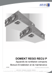
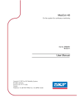
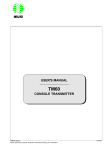
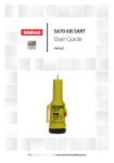
1
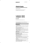
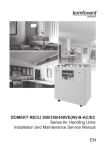
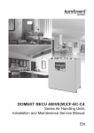
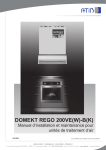
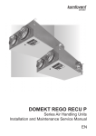
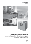
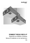
DOMEKT ReGO 400VE(W)-B
Series Air Handling Units
Installation and Maintenance Service Manual
EN
Content
Safety Requirements
...................................................................................3
Transportation
...................................................................................3
Brief Description of the Unit
...................................................................................5
Installation
...................................................................................6
Maintenance
.................................................................................11
Technical Information
.................................... ............................................13
Ordering Key
.................................................................................15
This symbol indicates that this product is not to be disposed of with your household waste, according to the WEEE Directive (2002/96/EC)
and your national law. This product should be handed over to a designated collection point, or to an authorised collection site for recycling
waste electrical and electronic equipment (EEE). Improper handling of this type of waste could have a possible negative impact on the
environment and human health due to potentially hazardous substances that are generally associated with EEE. At the same time, your
cooperation in the correct disposal of this product will contribute to the effective usage of natural resources. For more information about
where you can drop off your waste equipment for recycling, please contact your local city office, waste authority, approved WEEE scheme
or your household waste disposal service.
2
Installation and Maintenance Service Manual
Safety Requirements
• To avoid accidents and/or unit damage, only a trained technician must carry
out the connection.
• The appropriate Personal Protective Equipment (PPE) attire is worn relative to
the operation being carried out.
• Electrical equipment is rated, connected and earthed in accordance with CE
regulations.
The air handling unit must be plugged in to an electrical outlet (with earth), which is in good order and
corresponds with all requirements of electric safety.
Before starting any operations inside the unit, make sure that the unit is switched off, and the power
cable is unplugged.
•
•
•
•
Earth must be installed according EN61557, BS 7671.
The unit should be installed according to Installation and Maintenance Manual.
Before starting the unit, check correct position of air filters.
Service maintenance should be carried out only in conformity with the
instructions specified herein below.
• If main cable is damaged, only manufacturer, service team or trained technician
must change it in order to avoid accidents.
Transportation
The air handling units are ready for transit and storage (1 Picture). The unit is packed to prevent damage of the
external and internal parts of the unit, dust and moisture penetration.
The unit is packed to box after that corners of the air handling units are protected against the damage –
protective corners are used. The entire unit is wrapped up in protective film. For transit or storage, units are mounted on timber pallets. The unit is fastened to the pallet with polypropylene packing tape over protective corners.
Air handling unit ready for transit and storage
1 Picture
We reserve the right to make changes without prior notice.
3
Installation and Maintenance Service Manual
Forklift truck or hand pallet truck can transport air handling unit as it is shown ( 2 a, b Pictures).
Air handling unit transportation by forklift truck or hand pallet truck
2 b Picture
2 a Picture
2 a Unit is transported by hand pallet truck on a wooden pallet;
2 b Unit is transported by forklift truck on a wooden pallet.
The unit should be examined upon receipt, to ensure that no visible damage has occurred during transit,
and the advice note checked to ensure that all items have been received. If damage or delivery shortages are
discovered, the carrier should be immediately informed. AMALVA should be notified within three days of receipt,
with a written confirmation sent within seven days. AMALVA can accept no responsibility for damage by unloading
from carrier or for subsequent damage on site.
If the unit is not to be installed immediately, it should be stored in a clean, dry area. If stored externally, it should
be adequately protected from the weather.
4
We reserve the right to make changes without prior notice.
Installation and Maintenance Service Manual
Brief Description of the Unit
• The air handling units are intended for ventilation of small and medium-sized spaces (eg. single family houses,
offices, etc.), having operating ambient temperature and relative humidity. The unit is intended to be installed in the kitchen or other domestic premises. Mineral wool is used for thermal insulation and sound
attenuation. Units cover panels are 25 mm thick. As standard, the unit is designed for indoor placement. The
operating temperature range for the unit is -300C ... 400C, outdoor air temperature.
The air handling unit is not to be used to transport solid particles, even not in areas where there is a risk of
explosive gases.
• DOMEKT REGO 400VE(W) (3 Picture) series units are equipped with a rotary heat exchanger, air filters, an
electric air heater, fans and automation control system, to ensure safe and efficient operation of the unit.
• Before you open the door, the unit must be switched off and the fans must have been given time to stop (up to
3 minutes).
• The unit contains heating elements that must not be touched when they are hot.
• To maintain a good indoor climate, comply with regulations and, to avoid condensation damage, the unit must
never be stopped apart from during service/maintenance or in connection with an accident.
• If the unit is placed in spaces with high humidity, condensation might occur on the surface of the unit when
outdoor temperatures are very low.
DOMEKT REGO 400VE(W)-B Air Handling Unit Scheme
D A
B C
C B
E
E
A D
5
3
3
5
2
4
4
2
7
E1
E
6
A
C
B
D
C
A
D
B
1. Rotary heat exchanger
2. Supply air filter
3. Exhaust air filter
4. Supply fan
5. Exhaust fan
6. Electric air heater *
7. Automation control system A.
B.
C.
D.
E.
3 Picture
Outdoor intake
Supply air
Extract indoor
Exhaust air
Kitchen hood connection (by-pass – extraction without heat recovery)
* AHU REGO-400VW-B is suitable for use with water duct air heater.
Note: to reduce the noise level to the premises, it is recommended to install sound attenuators in the ducts.
We reserve the right to make changes without prior notice.
5
Installation and Maintenance Service Manual
Installation
Unit Inspection
Before installing the unit, inspection must be carried out. Unit has removable panels from its both sides (4 Picture).
4 Picture
All internal unit components can be extracted from inspection side. After choosing desired inspection side, it is necessary to check if rotary heat exchanger, electric heater and automatics box are positioned correctly. Rotary heat
exchanger and automatics box are maintained from inspection side. Picture 4 shows unit with left-hand inspection side. To get unit with right-hand inspection side, internal unit elements must be turned round. Remove both
unit’s panels, which afterwards must be counterchanged to have possibility of other side inspection. Start with
electric heater (5 Picture). After removing the cover of the electric heater, electrical connection with the rotor must
be disconnected.
unplug
plug
5 Picture
Taking off the switch from the unit it is needed to take it apart from each other and check if the contacts are
fouled.
6
We reserve the right to make changes without prior notice.
Installation and Maintenance Service Manual
Afterwards electric heater may be extracted, turned round and put in by its other side (6 Picture). Then rotary
heat exchanger and automatics box must be turned round being already disconnected from all connections and
with unscrewed grounding wires (7 Picture).
unscrew
disconnect
pull and screw
6 Picture
7 Picture
Screw off and remove top covers of automatics and by-pass. Afterwards they must be counterchanged and
screwed again (8 a, b Pictures).
8b Picture
8a Picture
We reserve the right to make changes without prior notice.
7
Installation and Maintenance Service Manual
Disconnect fans’ connections; pull out air temperature sensor together with a rubber plug. Loosen all wires
fixed in the partitions with rubber gaskets and extract rotary heat exchanger (9 Picture).
pull
disconnect
9 Picture
While unit casing is disassembled, all protective gaskets from the unit back side must be removed on its front
one (10 Picture). Then assemble in inverse way to get the unit of opposite inspection side.
10 Picture
Before inserting rotary heat exchanger, one by-pass cover which is located in it must be removed. Cover is
unscrewed with six screws. This is done to have correct by-pass air flow direction. Opened vent must always be
near exhaust flow fan (11 Picture).
Note: There are two by-pass covers by default. When connecting the by-pass, one cover must be removed.
11 Picture
8
We reserve the right to make changes without prior notice.
Installation and Maintenance Service Manual
Insert rotor by its correct side; put on protective gaskets to their places (12 Picture).
When changing inspection sides, be sure fans’ connecting plugs are not counterchanged. Fans are connected by the same connections. In case if unit is right-hand
side, fans wires are crossed over in rotary heat exchanger’s electronics place. Also
by crossing the wires, correct air temperature sensor position will be achieved.
12 Picture
Then electric heater is connected (13 Picture), cables must be carefully connected and fixed to appropriate
places. Do not forget to screw on grounding wires and make connections in indicated places.
13 Picture
Picture 14 shows unit from right-hand inspection side.
14 Picture
Do not forget to put on elements for hanging before screwing on back panel.
Use the same instruction of changing the inspection side of AHU, but without the notes of electric heater.
We reserve the right to make changes without prior notice.
9
Installation and Maintenance Service Manual
The place for the unit should be selected with allowance for minimum access to the unit for maintenance and
service inspection. The minimum free space in front of the inspection panel should be not less than 600 mm. It
is recommended to install the air handling unit in a separate room (15 Picture).
Unit brackets’ positions
O125
O160
30
604
641
662
57
A
B
30
300
15 Picture
600
Pictures 16 a and 16 b show unit’s upper and bottom fixing element.
9
1
2
3
4
5
8
7
6
2
16a Picture
1. Screw
4. Hanging bracket 2
7. Self tapping screw
2. Wall plug
5. Bolt M5
8. L-shape bracket
3. Hanging bracket 1
6. Gasket
9.
1
16b Picture
Washer M5 DIN9021
Final Inspection
After installation of the unit, a thorough inspection should be carried out. This should include inspecting the
inside of the unit and removing debris and tools, which may have been left behind by on site contractors. Replace
any panels, which may have been removed and close all access doors, ensuring that the door sealing gaskets
have not been damaged.
10
We reserve the right to make changes without prior notice.
Installation and Maintenance Service Manual
Heating coil connection* and the pipe work should be done in order to ensure the space for maintenance and
service work. When carrying out the installation of heater pipes, make sure that hot water supply is completely
disconnected. Before start-up of the air handling unit, the heater system should be filled in with water. Glycol is
used in the air handling units with coil heat exchanger. Never pour glycol down a drain; collect it in a receptacle
and leave it at a recycling centre or the like. Glycol is highly dangerous to consume and can cause fatal poisoning
or damage the kidneys. Contact a doctor! Avoid breathing glycol vapour in confined spaces. If you get glycol in
your eyes, fush them thoroughly with water (for about 5 minutes).
*If water heater build in.
When operating air handling unit in the temperatures lower than 0°C, it is
necessary to use glycol additionally or assure the reversible heating agent
temperature more than 25°C.
It is important to maintain air heaters and coolers cleanliness; that is to change
filters installed in the air handling unit on time. If the air heater or cooler gets dirty,
to perform periodical cleaning.
Maintenance
It is recommended to carry out routine maintenance of the air handling unit KOMFOVENT DOMEKT
REGO 400VE(W) 3 – 4 times per year. Extracting unit elements (see 17 Picture). Cables must be disconnected
when extracting electric heater and rotary heat exchanger.
17 Picture
During inspection, the following operations should be performed:
1. Rotary heat exchanger check. Inspection of the rotary heat exchanger is performed once per year. Free
rotation of the rotary heat exchanger, continuity of the rotating belt, absence of damages of the rotor drums
and the seal gasket are checked. It is necessary to check the stretch of belt. Free belt will slide and the efficiency of rotary heat exchanger will fall down. To reach maximal efficiency, rotor must turn at least 6 times
per minute. Polluted heat exchanger will decrease efficiency. Cleaning can be performed by compressed
air or soapsuds. Check out water falling on the rotor’s electric motor.
Rotor cleaning. If rotor cleaning by compressed air is not effective, it can be washed with soapsuds
(18 Picture), or if needed – use degreasing soak for metal (aluminum) cleaning. Check out water falling
on the rotor’s electric motor and other automatics’ elements. In case if water got into details, they must be
urgently dry up. Leave rotor to dry in a warm place. Rotor can be connected only when it is absolutely dry.
We reserve the right to make changes without prior notice.
11
Installation and Maintenance Service Manual
Rotor cleaning
18 Picture
2. Fans check (once per year). Polluted fans decrease efficiency.
Before performing any inspection work, check whether the unit is switched off
from the electric power supply.
Fans should be carefully cleaned with textile or soft brush. Do not use water. Do not break balance. Check
if fan freely rotates and is not mechanically damaged, if impeller does not touch suction nozzles, fan does
not spread noise and mounting bolts are screwed.
3. Air heater check. Check if electric air heater is properly fixed, wires connections are not damaged and heating elements are not bent. Check the plates of water air heater. The air heater is cleaned with hoover from
supply air side or with air blast from exhaust air side. If it is very dirty, wash with tepid water, which will
not make corrosion of aluminium. Check if position of return water temperature sensor is right. They can
be damaged or bent due to uneven heat or uneven and turbulent air direction. Check if electric air heater is
clear of unnecessary things and heating elements are not clogged, because this can cause unpleasant smell
or in the worst case – dust can start burning. Air flow through the air heater should be greater than 1,5 m/s.
Heating elements can be cleaned with hoover or wet textile.
4. Air filter clogging check. Change air filters when air filter clogging is indicated. We recommend to change
filters at least twice per year: before and after heating season, or more*. Filters are one time used. We do
not recommend cleaning them. Stop the air handling unit before changing filters.
* Clogged filters unbalance ventilation system, air handling unit uses more power.
12
We reserve the right to make changes without prior notice.
Technical Information
Specifications
REGO 400VE(W)
Dimensions
m3/h
kg
kW
W
V / Hz
A
mm
%
kW
Nominal air flow
Unit weight
Heater capacity
Fans input power
Supply voltage
Maximal operating current
Ducts connection
Thermal efficiency of rotary heat exchanger up to
Energy recovery of rotary heat exchanger up to
AC VE/VW
300
40
1,0 / 1,2
2x137
~230 / 50 /1 phase
5,75 / 1,41
160
82
3,5
EC VE/VW
300
41
1,0 / 1,2
2x70
~230 / 50 /1 phase
5,15 / 0,76
160
82
3,5
Filters
Supply air
F5 / F7
Panel
450x210x46
Filter class
Filter type
Filters dimensions bxhxl
Exhaust air
F5 / F7
Panel
450x210x46
Dimensions
mm
Acoustic data of REGO 400VE(W)-B-AC
Supply air flow
(into air ducts)
Intake
63
125
250
500
1000
2000
4000
8000
dB(A)
56
54
53
53
51
49
45
39
56,2
Supply
60
62
63
61
60
58
54
50
65,0*
Extract
56
54
53
53
51
50
45
40
56,4
Exhaust
60
62
63
61
60
58
54
50
65,0
Kitchen hood connection
59
59
59
59
58
58
56
48
62,7
Surrounding (3 m distance)
52
53
51
44
37
32
27
23
46,5
Exhaust air flow
(into air ducts)
* For AHU REGO 400VW-B, sound power less up to 2 dB(A).
Acoustic data of REGO 400VE(W)-B-EC
Supply air flow
(into air ducts)
Intake
63
125
250
500
1000
2000
4000
8000
dB(A)
49
47
43
43
45
41
38
36
48.8
Supply
55
56
54
54
54
52
50
48
59.0*
Extract
49
47
43
43
45
41
38
36
48.8
Exhaust
55
56
54
54
54
52
50
48
59.0
Kitchen hood connection
53
51
47
48
50
49
47
45
55.2
Surrounding (3 m distance)
47
47
44
38
32
29
25
22
40.3
Exhaust air flow
(into air ducts)
* For AHU REGO 400VW-B, sound power less up to 1,5 dB(A).
We reserve the right to make changes without prior notice.
13
Installation and Maintenance Service Manual
Static pressure, Pa
Power consumption, W
REGO 400VE(W*)-B-AC Performance
Air volume, m3/h
Static pressure, Pa
Power consumption, W
REGO 400VE(W*)-B-EC Performance
Air volume, m3/h
* Correction factor for REGO 400VW - 15Pa
14
We reserve the right to make changes without prior notice.
Installation and Maintenance Service Manual
563
547
Scheme
600
91
125
232
500
418
133
160(4x)
300
Ordering Key
REGO – 400
–V
E(W) – B
AC / EC – C4
–F
Filter class (F5 or F7)
Controller type: C4
Motor type: AC – alternating current,
EC – electronically commutated
By - pass
Air heater: W-water, E-electric
Version: vertical
Unit size (shows nominal air flow)
AHU type:
REGO – with rotary heat exchanger
We reserve the right to make changes without prior notice.
15
UAB AMALVA
Ozo str. 10,
LT–08200 Vilnius, LITHUANIA
e-mail [email protected]
www.amalva.com
www.komfovent.com2012