1
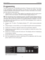
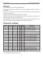
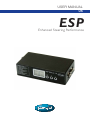
USER MANUAL
US
ESP
Enhanced Steering Performance
ESP
Enhanced Steering Performance
Produced and published by Permobil AB, Sweden
Edition 2, 2008-1
Product code: 205008-US-0
How to contact Permobil
Head Office of the Permobil group
ESP User Manual
Contents
Contents
Introduction .................................................................................................... 6
Safety rules.................................................................................................... 7
Programming ................................................................................................ 8
Parameter settings ........................................................................................ 9
Program version .......................................................................................... 10
Troubleshooting .......................................................................................... 10
Resetting the factory settings and calibrating the sensor ............................11
5
ESP User Manual
Introduction
Introduction
The task of the ESP module is to give your wheelchair safer driving properties.
ESP stands for Enhanced Steering Performance.
The ESP module is programmed by Permobil to give the wheelchair optimum
performance. Customization may mean that small adjustments are necessary
afterwards. Adjustments to the preprogrammed parameters may only be made
by an engineer with good knowledge of the ESP module.
The ESP module is installed on the wheelchair chassis. See the chassis service
manual for further information.
The ESP module is connected between the wheelchair actuator and the output
stage, Pilot+. The module contains a sensor that measures the wheelchair’s
course deviations. A processor uses the information to correct any deviations
from the course the user set using the wheelchair actuator. The ESP module
uses the information from the sensor and the actuator to calculate a correct
control signal. The control signal is then passed to the wheelchair output stage,
Pilot+, which controls the drive motors.
Operation of the ESP module requires access to the full capacity of the output
stage. Pilot+’s various parameters therefore need to be adjusted to predefined
values to guarantee full maneuverability.
NB. The parameters in the Pilot+ output stage are set by Permobil and
must not be changed. If changes need to be made to the wheelchair
properties, they must be made via adjustments to the ESP module. The
ESP module has built-in functions to control wheelchair performance,
acceleration, course stability, etc.
6
ESP User Manual
Safety rules
Safety rules
-
No changes may be made to the Pilot+ output stage parameters.
Reprogramming with PP1c, ESP PC Programmer or similar equipment may
not take place.
-
The ESP module may only be programmed by engineers who have good
knowledge of ESP functions.
-
Changes made to the parameters of the ESP module must be documented.
Note the values of the parameters before and after changes.
-
The ESP module is supplied preprogrammed for best performance. Any
change to a parameter’s value should mean a reduction in the value.
Increasing a parameter’s value may cause the wheelchair to become unstable
and hard to maneuver.
-
When changes have been made to the ESP module parameters, the wheelchair
must be test-driven before it is returned to the user.
NB. If tests are carried out with the ESP module disconnected, you should
be aware that the control characteristics are set to very high values. This
makes the wheelchair hard to maneuver. Ensure that there is adequate free
space around the wheelchair where the test is carried out.
7
ESP User Manual
Programming
Programming
The ESP module has 16 adjustable parameters. Changes are made to the values
of the parameters using three buttons on the front of the module. The ESP
module is installed on the wheelchair chassis For further information on its location,
see the chassis service manual.
1. Hold down the “S” button while starting the wheelchair with the main power
switch on the control panel. The ESP module display displays “P1”.
NB If the wheelchair has an additional joystick, the ESP module display displays
“CJ” for a short while. This means that the joystick’s neutral position is being
calibrated. Ensure that the joystick is in its neutral position on startup. If it is not,
the calibration will fail and the error code “E6” will be displayed. Error codes are
discussed on page 10.
2. Release the “S” button. The display displays “01”, which means parameter
no. 1.
3. Using the plus or minus button, you can step through the various parameters.
4. Press the “S” button to read the value for the parameter selected.
5. Using the plus or minus button, you can increase or reduce the value of the
parameter selected.
6. Press the “S” button to save the value set. The display returns to displaying
the parameter number.
7. Scroll with the plus or minus button to another parameter.
8. Exit the programming mode by switching off the wheelchair with the main
power switch on the control panel.
ERROR CODES
E1: OMNI+/JOYSTICK+
E2: DATA TIME OUT
E3: SENSOR
E4: PROCESSOR ADC
E5: ATT JOYSTICK
E6: EPROM
E7: INTERNAL/CODE
E8: WATCHDOG
ESP Module-JS
S
ESP module front panel.
8
+
-
ESP User Manual
Programming & parameter settings
Example:
The wheelchair is too fast in speed position 5.
To reduce the maximum speed, go to the programming mode and step to
parameter 9.
Press the “S” button to see the current setting. Adjust the value downwards
using the minus button.
Save the value set by again pressing the “S” button.
Switch off and then start the wheelchair with the main power switch on the
control panel to test-drive the wheelchair.
Remember that the maximum speed is reduced if the seat lift is raised. The seat
lift must, therefore, be in its lowest position during the test drive.
Parameter settings
Number
Standard
Range*
Min. Max. Step
Designation
1
15
10 - 75
5
95
5
Max. acceleration (speed 5)
2
15
5 - 50
5
95
5
Max. acceleration (speed 1)
3
75
20 - 75
5
95
5
Max. deceleration (speed 5)
4
30
10 - 70
5
95
5
Max. deceleration (speed 1)
5
40
25 - 75
5
95
5
Max. turn acceleration (speed 5)
6
15
10 - 50
5
95
5
Min. turn acceleration (speed 1)
7
60
35 - 80
5
95
5
Max. turn deceleration (speed 5)
8
40
30 - 60
5
95
5
Min. turn deceleration (speed 1)
9
95
20 - 95
5
95
5
Max. forward speed (speed 5)
10
15
10 - 80
5
95
5
Min. forward speed (speed 1)
11
25
10 - 50
5
95
5
Max. reverse speed (speed 5)
12
10
10 - 30
5
95
5
Min. reverse speed (speed 1)
13
80
50 - 90
5
95
5
Max. turning speed (speed 5)
14
65
25 - 80
5
95
5
Min. turning speed (speed 1)
15
2
N/A
1
5
1
Attendant high speed selection
16
1
N/A
1
5
1
Attendant low speed selection
* Recommended range for most users.
9
ESP User Manual
Program version & troubleshooting
Program version
The ESP module program version is displayed in the display for a second when
the wheelchair is started using the main power switch on the control panel.
Example: The ESP module display displays 60 on startup. This means that the
ESP module has program version 6.0.
Troubleshooting
When the wheelchair electronics system indicates an error in the output stage, it
may also be the ESP module that found an error. The ESP module troubleshoots
all vital parts continuously. If an error is found, the wheelchair stops and an error
code is displayed in the ESP module display. When the error code has been
read off, suitable action can be taken according to the table below.
Error
code
Designation
E1
OMNI+/Joystick
+
Control panel sending
Control panel
error message
E2
Data time out
Interruption in data
communication
ESP module, cables, control
panel or output stage
E3
Sensor
Sensor error
ESP module
E4
Processor ADC
Sensor error
ESP module
E5
Att Joystick
Additional joystick
error
Additional joystick
E6
EPROM
EPROM data error
ESP module, reset factory settings, calibrate
E7
Internal/Code
Software code error
ESP module
E8
Watchdog
Processor error
ESP module
E9
Profile change
Operating error
Switch off the main power switch
on the control panel. Switch it on
again.
Remark
10
Check and/or replace
ESP User Manual
Resetting and calibrating
Resetting the basic settings and calibrating
the sensor
Calibrate the sensor and return to the settings the ESP module had on delivery
from Permobil:
- if the wheelchair does not keep a sufficiently straight course when driven
forwards.
- after problems with EPROM data. Error code E6, see page 10.
Resetting and calibrating
1. The main power switch on the control panel must be off.
2. Hold down the “S”, plus and minus buttons while starting the wheelchair with
the main power switch on the control panel.
The display displays “CS”. The parameters are reset to the values they had
on delivery from Permobil and sensor calibration begins.
Sensor calibration can take up to ten minutes.
When calibration is complete, “—” is displayed in the display.
If calibration fails, “Er” (error) is displayed in the display.
Calibration can be repeated from point one if the error message “Er” was
displayed.
3. Exit the programming mode by switching off the wheelchair with the main
power switch on the control panel.
Important!
-
The ESP module must be completely still during the calibration process.
Calibration must take place at room temperature, 18 to 25°C.
The ESP module should be on for at least 20 minutes before calibration
begins. This is to ensure that the sensor has the correct working temperature.
11
ESP User Manual
Notes
12
ESP User Manual
Notes
13
Product code: 205008-US-0