1
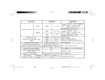
1113-01
ENGINE ASSEMBLY
01-3
1113-01
GENERAL
1. DESCRIPTION AND OPERATION
1) Cleanliness and Care
An automobile engine is a combination of many machined, honed, polished and lapped
surfaces with tolerances that are measured in the ten-thousanths of an inch.
When any internal engine parts are serviced, care and cleanliness are important.
A liberal coating of enigne oil should be applied to friction areas during assembly, to protect and
lubricate the surfaces on initial operation. Proper cleaning and protection of machined surfaces
and friction areas is part of the repair procedure.
This is considered standard shop practice even if not specifically stated.
Whenever valve train components are removed for service, they should be kept in order. They
should be installed in the same locations, and with the same mating surfaces, as when they
were removed.
Battery cables should be disconnected before any major work is performed on the engine.
Failure to disconnect cables may result in damage to wire harness or other electrical parts.
ENGINE ASSEMBLY
KYRON 2010.01
01-4
1113-01
2) On-engine Service
- Disconnect the negative battery cable before removing or installing any electrical unit, or
when a tool or equipment could easily come in contact with exposed electrical terminals.
Disconnecting this cable will help prevent personal injury and damage to the vehicle. The
ignition must also be in LOCK unless otherwise noted.
- Any time the air cleaner is removed, the intake opening should be covered. This will
protect against accidental entrance of foreign material, which could follow the intake
passage into the cylinder and cause extensive damage when the engine is started.
ENGINE ASSEMBLY
KYRON 2010.01
1113-01
01-5
2. G23D ENGINE ASSEMBLY
Front View
Rear View
ENGINE ASSEMBLY
KYRON 2010.01
01-6
1113-01
LH Side View
RH Side View
ENGINE ASSEMBLY
KYRON 2010.01
1113-01
01-7
3. G23D ENGINE STRUCTURE
Front View
Side View
ENGINE ASSEMBLY
KYRON 2010.01
01-8
1113-01
▶ Front View
NO.
FUNCTION
NO.
FUNCTION
1
HFM Sensor
12
Intake Manifold
2
Intake Air Duct
13
Cylinder Head
3
Cylinder Head Cover
14
Exhaust Manifold
4
Ignition Coi
15
Dipstick Guide Tube and Gauge
5
Spark Plug Connector
16
Connecting Rod
6
Fuel Distributor
17
Crankshaft
7
Injector
18
Engine Mounting Bracket
8
Exhaust Camshaft
19
Starter
9
Intake Camshaft
20
Crankcase
10
Valve Tappet
21
Oil Pump Sprocket
11
Intake Valve
22
Oil Pan
▶ Side View
NO.
FUNCTION
NO.
FUNCTION
23
Camshaft Adjuster
29
Oil Pump Drive Chain
24
Oil Filler Cap
30
Oil Strainer
25
Engine Hanger Bracket
31
Oil Pump
26
Cooling Fan and Viscous Clutch
32
Ring Gear and Flywheel of Drive Plate
27
Oil Filter
33
Piston
28
Timing Chain
ENGINE ASSEMBLY
KYRON 2010.01
1113-01
01-9
4. DIAGNOSTIC INFORMATION AND PROCEDURE
1) Oil Leak Diagnosis
Most fluid oil leaks are easily located and repaired by visually finding the leak and replacing or
repairing the necessary parts. On some occasions a fluid leak may be difficult to locate or
repair. The following procedures may help you in locating and repairing most leaks.
▶ Finding the Leak
- Identify the fluid. Determine whether it is engine oil, automatic transmission fluid, power
steering fluid, etc.
- Identify where the fluid is leaking from.
· After running the vehicle at normal operating temperature, park the vehicle over a
large sheet of paper.
· Wait a few minutes.
· You should be able to find the approximate location of the leak by the drippings on
the paper.
- Visually check around the suspected component.
Check around all the gasket mating surfaces for leaks. A mirror is useful for finding leaks
in areas that are hard to reach.
- If the leak still cannot be found, it may be necessary to clean the suspected area with a
degreaser, steam or spray solvent.
· Clean the area well.
· Dry the area.
· Operate the vehicle for several miles at normal operating temperature and varying
speeds.
· After operating the vehicle, visually check the suspected component.
· If you still cannot locate the leak, try using the powder or black light and dye method.
▶ Powder Method
-
Clean the suspected area.
Apply an aerosol-type powder (such as foot powder) to the suspected area.
Operate the vehicle under normal operating conditoins.
Visually inspect the suspected component. You should be able to trace the leak path
over the white powder surface to the source.
ENGINE ASSEMBLY
KYRON 2010.01
01-10
1113-01
▶ Black Light and Dye Method
A dye and light kit is available for finding leaks, Refer to the manufacturer's directions when
using the kit.
- Pour the specified amount of dye into the engine oil fill tube.
- Operate the vehicle normal operating conditions as directed in the kit.
- Direct the light toward the suspected area. The dyed fluid will appear as a yellow path
leading to the source.
▶ Repairing the Leak
Once the origin of the leak has been pinpointed and traced back to its source, the cause of the
leak must be determined in order for it to be repaired properly.
If a gasket is replaced, but the sealing flange is bent, the new gasket will not repair the leak.
The bent flange must be repaired also. Before attempting to repair a leak, check for the
following conditions and correct them as they may cause a leak.
▶ Gaskets
-
The fluid level/pressure is too high.
The crankcase ventilation system is malfunctioning.
The seal bore is damaged (scratched, burred or nicked).
The seal is damaged or worn.
Improper installation is evident.
There are cracks in the components.
The shaft surface is scratched, nicked or damaged.
A loose or worn bearing is causing excess seal wear.
ENGINE ASSEMBLY
KYRON 2010.01
1113-01
01-11
2) Compression Pressure Test
▶ Standard Service Data
- A9912 0012B (001 589 76 21 00) Compression Pressure Tester
▶ Measuring Procedure
- Warm the engine up to normal operating temperature.
- Remove the spark plugs using the spark plug wrench.
- Place the diagram sheet to compression pressure tester A9912 0012B (001 589 76 21
00).
- Connect the adaptor to compression pressure tester A9912 0012B (001 589 76 21 00)
and install it into the spark plug hole.
- Crank the engine approx. eight revolutions by using the start motor.
- Compare the measurements of compression pressure tester A9912 0012B (001 589 76
21 00) with the specifications.
- Measure the compression pressure of the other cylinders in the same way.
- If measured value is not within the specifications, perform the cylinder pressure leakage
test.
- Discharge the combustion residues in the cylinders before testing the compression
pressure.
- Apply the parking brake before cranking the engine.
ENGINE ASSEMBLY
KYRON 2010.01
01-12
1113-01
3) Cylinder Pressure LeakageTest
▶ Permissible Pressure Leakage
At Whole Engine
Max. 25 %
At Valve and Cylinder Head Gasket
Max. 10 %
At Piston and Piston Ring
Max. 20 %
▶ Cylinder Number
OT (TDC)
1, 4
UT (BDC 180 °)
2, 3
▶ Cylinder Number
Cylinder Pressure
Leakage Tester
ENGINE ASSEMBLY
KYRON 2010.01
Bosch, EFAW210A
Sun, CLT 228
1113-01
01-13
▶ Leakage Test
-
Warm the engine up to normal operating temperature.
Disconnect the negative battery cable.
Remove the spark plugs.
Check the coolant level by opening the coolant reservoir cap and replenish if insufficient.
Open the engine oil filler cap.
Connect the tester to air pressure line and adjust the scale of tester.
Install the connecting hose to spark plug hole.
Position the piston of No.1 cylinder at TDC by rotating the crankshaft.
Connect the connecting hose to tester and measure the leakage volume after blowing up
5 bar of compressed air.
- Measure the leakage volume in the completely opening condition of throttle valve by
pulling the acceleration cable.
- Perform the pressure test according to the firing order.
- Firing Order: 1 - 3 - 4 - 2
- Compare the leakage pressure with the specifications.
ENGINE ASSEMBLY
KYRON 2010.01
01-14
1113-01
5. GENERAL DIAGNOSIS
ENGINE ASSEMBLY
KYRON 2010.01
1113-01
01-15
▶ General Diagnosis (Cont'd)
ENGINE ASSEMBLY
KYRON 2010.01
01-16
1113-01
▶ General Diagnosis (Cont'd)
ENGINE ASSEMBLY
KYRON 2010.01
1113-01
01-17
▶ General Diagnosis (Cont'd)
ENGINE ASSEMBLY
KYRON 2010.01
01-18
1113-01
▶ General Diagnosis (Cont'd)
ENGINE ASSEMBLY
KYRON 2010.01
1113-01
01-19
6. SPECIFICATIONS
1) Engine Specifications
MSE : Engine Control Module
3.53D : 4 Cylinder Version
ENGINE ASSEMBLY
KYRON 2010.01
01-20
1113-01
2) Fastener Tightening Specifications
ENGINE ASSEMBLY
KYRON 2010.01
1113-01
01-21
▶ Fastener Tightening Specifications (Cont'd)
ENGINE ASSEMBLY
KYRON 2010.01
01-22
1113-01
2) Performance Curve
ENGINE ASSEMBLY
KYRON 2010.01
1713-08
ENGINE INTAKE SYSTEM
02-3
1713-08
GENERAL
1. SPECIFICATIONS
(1) Fastener Tightening Specifications
ENGINE INTAKE SYSTEM
KYRON 2010.01
ENGINE EXHAUST SYSTEM
2420-01
ENGINE EXHAUST SYSTEM
GENERAL
1. SPECIFICATION ...................................
3
OVERVIEW AND OPERATION
PROCESS
1. DESCRIPTION AND OPERATION .........
4
REMOVAL AND INSTALLATION
2420-01 EXHAUST LINE............................
7
2420-01
ENGINE EXHAUST SYSTEM
03-3
2420-01
GENERAL
1. SPECIFICATION
(1) Fastener Tightening Specifications
ENGINE EXHAUST SYSTEM
KYRON 2010.01
03-4
2420-01
OVERVIEW AND OPERATION PROCESS
1. DESCRIPTION AND OPERATION
1) Exhaust System
When you are inspecting or replacing exhaust system components, make sure there is
adequate clearance from all points on the underbody to avoid possible
overheating of the floor panel and possible damage to the passenger compartment insulation
and trim materials.
Check the complete exhaust system and the nearby body areas and trunk lid for broken,
damaged, missing or mispositioned parts, open seams, holes, loose connections, or other
deterioration which could permit exhaust fumes to seep into the trunk may be an indication of
a problem in one of these areas. Any defects should be corrected immediately.
2) Catalytic Converter (Gasoline Engine)
1. When jacking or lifting the vehicle from the body side rails, be certain that the lift pads do not
contact the catalytic converter, as this could damage the catalytic converter.
2. Use of anything other than unleaded fuel will damage the catalyst in the catalytic converter.
▶ Catalytic Converter Structure
ENGINE EXHAUST SYSTEM
KYRON 2010.01
The Catalytic converter of monolith type consists
of 2 walled metal bodies which is made of
Cordierite. The principal element of converter
consists of the materials like Alumina or oxidized
Serume in order to apply to Ceramic Monolith.
Washer coat operates first, and catalytic metal
elements (Pt, Pd, Rh) operates to washer coat
next.
Monolith type is lighter than other types, easy to
manufacture and quickly approaches to proper
temperature. Washer coat is used to make a
contact surface with exhaust gas bigger by
adhering closely to small holes
of inner layer. If a lead compound or phosphorus
adheres to the surface and the temperature
rises, its surface is decreased. The total area of
general monolith converter is about 45,
000~500,000ft3. (10 times of a football field)
Generally Alumina (AL2 O3) is used as a raw
materialand its 7 phases of gamma, delta, theta
have big areas and high stability for the
temperature, and nowadays gamma Alumina is
used usually.
2420-01
03-5
▶ Catalytic Converter and Temperature
Catalytic converter has the normal function
of purification at a range of the temperature.
Because it has a weak point of decreasing of
the purification rate in the condition of
continuous high temperature, it should keep
the temperature range of 400 to 500°C for
normal condition. HC purification rate
becomes better according to the increase of
temperature in the normal range of
temperature. CO purification rate becomes
the best near the temperature of 450°C,
and NOx does so near the temperature of
400 to 500°C.
▶ Purification of Catalytic Converter
- Adhesion of soluble organic fraction
(SOF) below 180°C
- Purification of soluble organic fraction
(SOF) over 180°C
Chemical reaction formula
SOF(HC)+O2 → CO2+H2O
2CO+O2 → 2CO2
2C2H6+7O2 → 4CO2+6H20
- By catalytic action of two primary catalytic
converter, oxidation occurs in order to
decrease HC and CO.
Oxygen adheres to catalytic
material : below 180°C
Catalytic material supplies
Catalytic material conversion
each CO and HC with O2 for
process by DOC
their oxidation : above 180°C
ENGINE EXHAUST SYSTEM
KYRON 2010.01
03-6
2420-01
▶ Method for Reduction of NOx
NOx is generated a great deal in case that combustion temperature and excess air factor are
high. EGR valve can decrease NOx (30 to 35% decrease) by making temperature of
combustion chamber fall by means of exhaust gas re-circulation.
- EGR valve is installed on the diesel engine of Musso, Korando, Istana and Rexton.
And micro switch is installed together to control EGR valve.
- The setting method of micro switch is identical with the existing one.
ENGINE EXHAUST SYSTEM
KYRON 2010.01
2112-01
ENGINE COOLING SYSTEM
04-3
2110-01
GENERAL
1. GENERAL SPECIFICATIONS
ENGINE COOLING SYSTEM
KYRON 2010.01
04-4
2112-01
2. FASTENER TIGHTENING SPECIFICATIONS
ENGINE COOLING SYSTEM
KYRON 2010.01
2112-01
04-5
OVERVIEW AND OPERATION PROCESS
1. COMPONENT LOCATOR
1. Reserver Tank
2. Deaeration Tube
3. Inlet Hose
4. Outlet Hose
5. 3 way Hose
6. Clamp
7. Clamp
8. Bolt (M6, 2 piece)
9. Radiator
10. Lower Radiator Insulator
11. Plate
12. Clip
13. Upper Radiator Insulator
14. Bracket
15. PWM Electric Fan
ENGINE COOLING SYSTEM
KYRON 2010.01
04-6
2112-01
2. DESCRIPTION AND OPERATION
1) General Description
The cooling system maintains the engine temperature at an efficient level during all engine
operating conditions.
When the engine is cold, the cooling system cools the engine slowly or not at all. This slow
cooling of the engine allows the engine to warm up quickly.
The cooling system includes a radiator and recovery subsystem, cooling fans, a thermostat and
housing, a water pump, and a water pump drive belt. The timing belt drives the water pump.
All components must function properly for the cooling system to operation. The water pump
draws the coolant from the radiator. The coolant then circulates through water jackets in the
engine block, the intake manifold, and the cylinder head. When the coolant reaches the
operating
temperature of the thermostat, the thermostat opens. The coolant then goes back to the
radiator where it cools.
This system directs some coolant through the hoses to the heat core. This provides for heating
and defrosting.
The coolant reservoir is connected to the radiator to recover the coolant displaced by
expansion from the high temperatures. The coolant reservoir maintains the correct coolant
level.
The cooling system for this vehicle has no radiator cap or filler neck. The coolant is added to
the cooling system through the coolant reservoir.
2) Radiator
This vehicle has a lightweight tube-and-fin aluminum radiator. Plastic tanks are mounted on the
upper and the lower sides of the radiator core.
On vehicles equipped with automatic transaxles, the transaxle fluid cooler lines run through the
radiator tank.
A radiator drain plug is on this radiator.
To drain the cooling system, open the drain plug.
3) Coolant Reservoir
The coolant reservoir is a transparent plastic reservoir, similar to the windshield washer
reservoir.
The coolant reservoir is connected to the radiator by a hose and to the engine cooling system
by another hose.
As the vehicle is driven, the engine coolant heats and expands. The portion of the engine
coolant displaced by this expansion flows from the radiator and the engine into the coolant
reservoir. The air trapped in the radiator and the engine is degassed into the coolant reservoir.
When the engine stops, the engine coolant cools and contracts. The displaced engine coolant
is then drawn back into the radiator and the engine. This keeps the radiator filled with the
coolant to the desired level at all times and increases the cooling efficiency.
Maintain the coolant level between the MIN and MAX marks on the coolant reservoir when the
system is cold.
ENGINE COOLING SYSTEM
KYRON 2010.01
2112-01
04-7
4) Water Pump
The belt-driven centrifugal water pump consists of an impeller, a drive shaft, and a belt pulley.
The impeller is supported by a completely sealed bearing.
The water pump is serviced as an assembly and, therefore, cannot be disassembled.
5) Thermostat
A wax pellet-type thermostat controls the flow of the engine coolant through the engine cooling
system. The thermostat is mounted in the thermostat housing to the front of the cylinder head.
The thermostat stops the flow of the engine coolant from the engine to the radiator to provide
faster warm-up, and to regulate the coolant temperature. The thermostat remains closed while
the engine coolant is cold, preventing circulation of the engine coolant through the radiator. At
this point, the engine coolant is allowed to circulate only throughout the heater core to warm it
quickly and evenly.
As the engine warms, the thermostat opens. This allows the engine coolant to flow through the
radiator wherethe heat is dissipated. This opening and closing of the thermostat permits enough
engine coolant to enter the radiator to keep the engine within proper engine temperature
operating limits.
The wax pellet in the thermostat is hermetically sealed in a metal case. The wax element of the
thermostat expands when it is heated and contracts when it is cooled.
As the vehicle is driven and the engine warms, the engine coolant temperature increases.
When the engine coolant reaches a specified temperature, the wax pellet element in the
thermostat expands and exerts pressure against the metal case, forcing the valve open. This
allows the engine coolant to flow through the engine cooling system and cool the engine.
As the wax pellet cools, the contraction allows a spring to close the valve.
The thermostat begins to open at 82°C(180
°F) and is fully open at 95°C(203°F). The
thermostat closes at 80°C (176°F).
6) Electric Cooling Fan
- Keep hands, tools, and clothing away from the engine cooling fans to help prevent
personal injury.
This fan is electric and can turn on even when the engine is not running.
- If a fan blade is bent or damaged in any way, no attempt should be made to repair or
reuse the damaged part. A bent or damaged fan assembly should always be replaced with
a new one to prevent possible injury.
ENGINE COOLING SYSTEM
KYRON 2010.01
04-8
2112-01
The cooling fans are mounted behind the radiator in the engine compartment. The electric
cooling fans increase the flow of air across the radiator fins and across the condenser on air
conditioned (A/C)-equipped vehicles.
This helps to speed cooling when the vehicle is at idle or moving at low speeds.
All models have two fans. The main fan is 320 mm (12. 6 inches) in diameter with seven blades
to aid the airflow through the radiator and the condenser. An electric motor attached to the
radiator support drives the fan.
The auxiliary fan is 320 mm (12.6 inches) in diameter.
▶ A/C Off or Non-AC Model
- The cooling fans are actuated by the engine control module (ECM) using a low-speed
cooling fan relay, a high-speed cooling fan relay and a cooling fan motor relay.
- The ECM will turn the cooling fans on at low speed when the coolant temperature
reaches 95°C(203°F) and at high speed when the coolant temperature reaches
105°C(221°F).
- The ECM will change the cooling fans from high peed to low speed at
100°C(212°F) and will turn the cooling fans off at 90°C (194°F).
▶ A/C On
- The ECM will turn the cooling fans on at low speed when the A/C system is on. The ECM
will change to high speed when the high side A/C pressure reaches 1860 kPa (269.8
psi).
- The cooling fans will return to low speed when the high side A/C pressure reaches 1378
kPa (199.8 psi).
7) Engine Coolant Temperature Sensor
The Engine Coolant Temperature (ECT) sensor uses a temperature to control the signal
voltage to the Engine Control Module (ECM).
8) Coolant Temperature Gauge
The coolant temperature gauge controls the instrument panel temperature indicator. The
coolant temperature gauge is located with ECT sensor.
ENGINE COOLING SYSTEM
KYRON 2010.01
2112-01
04-9
3. PWM (PULSE WIDTH MODULATION) ELECTRIC FAN
OPERATION
1) Function
The PWM (Pulse Width Modulation) high capacity electric fan is installed instead of electric
condenser fan to enhance the durability and controllability and reduce noise.
2) Mounting Location
PWM
Fan shroud
PWM unit
Electric fan
ENGINE COOLING SYSTEM
KYRON 2010.01
04-10
2112-01
3) PWM Electric Fan
(1) Advantages and Disadvantages of the PWM Electric Fan
▶ Advantages
- Enhanced A/C performance: at low
speed, at idling, driving in city
- Reduction of vibration/noise: fan
activated by PWM only when necessary
- Reduction of engine consuming power
(V/Fan driving force) by 4 Hp - Cost
saving
▶ Disadvantage
- Poor engine cooling perfomance at low
and high rpm
4) PWM (Pulse Width Modulation) Unit
It controls the time of the output voltage to
control the fan motor speed independently.
▶ Internal functions
- Motor power shutting-off function when
overcurrent is applied
- Adverse voltage prevention function
- Detection function for the motor lock
- Temperature detecting function:
The electric fan operates at FULL speed to
cool down the PWM unit when the interior
temperature of PWM unit is over
120~150°C.
- Communication function when failing:
The fail signal is transmitted to the ECU
when the PWM unit is malfunctioning.
- Soft start function: The motor speed is
gradually increased when the motor is
initially operated.
ENGINE COOLING SYSTEM
KYRON 2010.01
2112-01
04-11
5) Shutting-off Condition of the A/C Compressor
▶ Coolant temperature
- When coolant temperature is below 20°C or over 115°C, engine speed is below 650
rpm or over 4500 rpm for 4 seconds after engine starting, abrupt acceleration and A/C
refrigerant pressure sensor detecting the followings
- A/C compressor is turned off when the refrigerant pressure is below 2.0 kg/cm2 and then
is turned on when the refrigerant pressure is over 2.4 kg/cm2.
- A/C compressor is turned off when the refrigerant pressure is over 30 kg/cm2 and then
is turned on when the refrigerant pressure is below 21.4 kg/cm2.
ENGINE COOLING SYSTEM
KYRON 2010.01
1452-01
ENGINE ELECTRIC DEVICES
05-3
0000-00
GENERAL
1. DIAGNOSTIC INFORMATION AND PROCEDURE
1) Ignition System
ENGINE ELECTRICAL SYSTEM
KYRON 2010.01
05-4
1452-01
2) Ignition System (Cont'd)
ENGINE ELECTRICAL SYSTEM
KYRON 2010.01
1452-01
05-5
OVERVIEW AND OPERATION PROCESS
1. DESCRIPTION AND OPERATION
1) Battey
The sealed battery is standard on all cars. There are no vent plugs in the cover.
The battery is completely sealed, except for two small vent holes in the sides.
These vent holes allow the small amount of gas produced in the battery to escape.
The battery has the following advantages over conventional batteries:
· No water addition for the life of the battery.
· Overcharge protection. If too much voltage is applied to the battery, it will not accept as
much current as a conventional battery.
In a conventional battery, the excess voltage will still try to charge the battery, leading
to gassing, which causes liquid loss.
· Not as liable to self-discharge as a conventional battery. This is particularly important when
a battery is left standing for long periods of time.
· More power available in a lighter, smaller case.
The battery has three major functions in the electrical system.
First, the battery provides a source of energy for cranking the engine.
Second, the battery acts as a voltage stabilizer for the electrical system. Finally, the battery
can, for a limited time, provide energy when the electrical demand exceeds the output of the
generator.
2) Ratings
▶ A battery has two ratings: (1) a reserve capacity rating designated at 27°C(80°F),
which is the time a fully charged battery will provide 25 amperes of current flow at or above
10.5 volts (2) a cold cranking amp rating determined under testing at -18°C(0°F),
which indicates the cranking load capacity.
(1)Reserve Capacity
The reserve capacity (RC) is the maximum length of time it is possible to travel at night with the
minimum electrical load and no generator output. Expressed in minutes, the RC rating is the
time required for a fully charged battery, at a temperature of 27°C(80°F) and being
discharged at a current of 25 amperes, to reach a terminal voltage of 10.5 volts.
ENGINE ELECTRICAL SYSTEM
KYRON 2010.01
05-6
1452-01
(2) Cold Cranking Amperage
The cold cranking amperage test is expressed at a battery temperature of -18°C(0°F).
The current rating is the minimum amperage, which must be maintained by the battery for 30
seconds at the specified temperature, while meeting a minimum voltage requirement of 7.2
volts.
This rating is a measure of cold cranking capacity.
The battery is not designed to last indefinitely. However, with proper care, the battery will
provide many years of service. If the battery tests well, but fails to perform satisfactorily in
service for no apparent reason, the following factors may point to the cause of the trouble:
· Vehicle accessories are left on overnight.
· Slow average driving speeds are used for short periods.
· The vehicle's electrical load is more than the generator output, particularly with the addition
of aftermarket equipment.
· Defects in the charging system, such as electrical shorts, a slipping generator belt, a faulty
generator, or a faulty voltage regulator.
· Battery abuse, including failure to keep the battery cable terminals clean and tight or a loose
battery hold-down clamp.
· Mechanical problems in the electrical system, such as shorted or pinched wires.
3) Charging Time Required
The time required to charge a battery will vary depending upon the following factors:
▶ Size of Battery - A Completely discharged large heavy-duty battery required more than twice
the recharging time as a completely discharged small passenger car battery.
▶ Temperature - A longer time will be needed to charge any battery at -18°C(0°F) than
at 27°C(80°F).
When a fast charger is connected to a cold battery, the current accepted by the battery will
be very low at first.
The battery will accept a higher current rate as the battery warms.
▶ Charger Capacity - A charger which can supply only 5 amperes will require a much longer
charging period than a charger that can supply 30 amperes or more.
▶ State-of-Charge - A completely discharged battery requires more than twice as much charge
as a onehalf charged battery.
Because the electrolyte is nearly pure water and a poor conductor in a completely
discharged battery, the current accepted by the battery is very low at first. Later, as the
charging current causes the electrolyte acid content to increase, the charging current will
likewise increase.
ENGINE ELECTRICAL SYSTEM
KYRON 2010.01
1452-01
05-7
4) Charging a Completely Discharged Battery (Off the Vehicle)
Unless this procedure is properly followed, a perfectly good battery may be needlessly
replaced.
The following procedure should be used to recharge a completely discharged battery:
1. Measure the voltage at the battery terminals with an accurate voltmeter.
If the reading is below 10 volts, the charge current will be very low, and it could take some
time before the battery accepts the current in excess of a few milliamperes.
Refer to "Charging Time Required" in this section, which focuses on the factors affecting
both the charging time required. Such low current may not be detectable on ammeters
available in the field.
2. Set the battery charger on the high setting.
Some chargers feature polarity protection circuitry, which prevents charger unless the
charger leads are correctly connected to the battery terminals.
A completely discharged battery may not have enough voltage to activate this circuitry, even
though the leads are connected properly, making it appear that the battery will not accept
charging current.
Therefore, follow the specific charger manufacturer's instruction for by passing or
overriding the circuitry so that the charger will turn on and charge a low-voltage battery.
3. Continue to charge the battery until the charge current is measurable. Battery chargers
vary in the amount of voltage and current provided. The time required for the battery to
accept a measurable charger current at various voltages may be as follows:
· If the charge current is not measurable at the end of the above charging times, the
battery should be replaced.
· If the charge current is measurable during the charging time, the battery is good, and
charging should be completed in the normal manner.
It is important to remember that a completely discharged battery must be recharged for a
sufficient number of ampere hours (AH) to restore the battery to a usable state.
· If the charge current is still not measurable after using the charging time calculated by
the above method, the battery should be replaced.
ENGINE ELECTRICAL SYSTEM
KYRON 2010.01
05-8
1452-01
5) Jump Starting Procedure
1. Position the vehicle with the charged battery so that the jumper cables will reach from the
charged battery to the battery that requires charging.
2. Turn off the ignition, all the lights, and all the electrical loads in both vehicles.
3. Leave the hazard flasher on if jump starting where there may be other traffic and any other
lights needed for the work area.
4. Apply the parking brake firmly in both vehicles.
In order to avoid damaging the vehicle make sure the cables are not on or near pulleys,
fans, or other parts that will move when the engine starts.
5. Shift an automatic transmission to PARK.
In order to avoid injury, do not use cables that have loose or missing insulation.
6. Clamp one end of the first jumper cable to the positive terminal on the booster battery. Make
sure it does not touch any other metal parts.
7. Clamp the other end of the same cable to the positive terminal on the discharged battery.
Never connect the other end to the negative terminal of the discharged battery.
Do not attach the cable directly to the neg-ative terminal of the discharged battery.
Doing so could cause sparks and possible battery explosion.
8. Clamp one end of the second cable to the negative terminal of the booster battery.
9. Make the final connection to a solid engine ground, such as the engine lift bracket at least
450 millimeters (18 inches) from the discharged battery.
10.Start the engine of the vehicle with the good battery.
Run the engine at a moderate speed for several minutes.
11.Then start the engine of the vehicle with the discharged battery.
12.Remove the jumper cables by reversing the above sequence exactly, removing the negative
cable from the vehicle with the discharged battery first.
While removing each clamp, take care that it does not touch any other metal while the other
end remains attached.
ENGINE ELECTRICAL SYSTEM
KYRON 2010.01
1452-01
05-9
6) Alternator
Alternators are equipped with internal regulators.
Unlike three-wire generators, the alternator may be used with only two connections: battery
positive and an "D+" terminal to the charge indicator lamp.
As with other charging systems, the charge indicator lamp lights when the ignition switch is
turned to RUN, and goes out when the engine is running.
If the charge idicator is on with the engine running, a charging system defect is indicated. This
indicator light will glow at full brilliance for several kinds of defects as well as when the system
voltage is too high or too low.
The regulator voltage setting varies with temperature and limits the system voltage by
controlling rotor field current.
Achieve correct average field current for proper system voltage control by varying the on-off
time. At high speeds, the on-time may be 10 percent and the off-time 90 percent.
At low speeds, with high electrical loads, the on-time may be 90 percent and the off-time 10
percent.
7) Charging System
Generators use a new type of regulator that incorporates a diode trio.
A Delta stator, a rectifier bridge, and a rotor with slip rings and brushes are electrically similar
to earlier generators.
A conventional pulley and fan are used.
There is no test hole.
8) Starter
Wound field starter motors have pole pieces, arranged around the armature, which are
energized by wound field coils.
Enclosed shift lever cranking motors have the shift lever mechanism and the solenoid plunger
enclosed in the drive housing, protecting them from exposure to dirt, icy conditions, and
splashes.
In the basic circuit, solenoid windings are energized when the switch is closed.
The resulting plunger and shift lever movement causes the pinion to engage the engine
flywheel ring gear.
The solenoid main contacts close. Cranking then takes place.
When the engine starts, pinion overrun protects the armature from excessive speed until the
switch is opened, at which time the return spring causes the pinion to disengage.
To prevent excessive overrun, the switch should be released immediately after the engine
starts.
ENGINE ELECTRICAL SYSTEM
KYRON 2010.01
05-10
1452-01
9) Starting System
The engine electrical system includes the battery, the ignition, the starter, the generator, and all
the related wiring.
Diagnostic tables will aid in troubleshooting system faults. When a fault is traced to a particular
component, refer to that component section of the service manual.
The starting system circuit consists of the battery, the starter motor, the ignition switch, and all
the related electrical wiring.
All of these components are connected electrically.
ENGINE ELECTRICAL SYSTEM
KYRON 2010.01
8510-23
CRUISE CONTROL SYSTEM
06-3
8510-23
OVERVIEW AND OPERATION PROCESS
1. CRUISE CONTROL SWITCH
The purpose of the cruise control system is to automatically maintain a vehicle speed set by the
driver, without depressing the accelerator pedal. The cruise control switch is located under the
right side of the steering wheel, and when this switch is operating "AUTO CRUISE" lamp comes
on.
The minimum speed for setting the cruise control system is 36 km/h (22.37 mph). Pay constant
attention to the distance between the vehicles and the traffic conditions when using the cruise
control system.
The cruise control system is a supplementary system, which helps the driver to drive the
vehicle at a desired speed without using the accelerator pedal under the traffic condition
where the vehicle-to-vehicle distance meets the legal requirement.
CRUISE CONTROL SYSTEM
KYRON 2010.01
06-4
8510-23
1) When To Use
Use the cruise control system only when (a) the traffic is not jammed, (b) driving on motorways
or highways where there is no sudden change in the driving condition due to traffic lights,
pedestrian, etc.
Use the cruise control system only when driving on motorways or highways. Do not use the
cruise control system where the road conditions are as follows:
- When there is strong wind or cross wind.
- Heavy traffic.
- Slippery roads or steep decline.
CRUISE CONTROL SYSTEM
KYRON 2010.01
8510-23
06-5
2. CIRCUIT DIAGRAM
1) Configuration
CRUISE CONTROL SYSTEM
KYRON 2010.01
06-6
8510-23
3. HOW TO OPERATE CRUISE CONTROL SWITCH
1) How To Set Speed
1. To operate the cruise control system, accelerate the vehicle to the speed within the specified
range below with depressing the accelerator pedal.
- Cruise control operating range: between 36 km/h (22.37 mph) and 150 km/h (93.207 mph)
2. When the desired speed is reached, which should be within the above range, push up the
cruise control switch lever to ACCEL side (upwards arrow), or push down the switch lever to
DECEL side (downwards arrow).
And then release the accelerator pedal slowly.
3. Now the vehicle is cruised by this system with the set speed. You don't need to use the
accelerator pedal.
4. Refer to the following pages for details of operation.
Never use the cruise control system until you get used to it.
Improper use or not fully aware of this function could result in collision and/or personal
injuries.
CRUISE CONTROL SYSTEM
KYRON 2010.01
8510-23
06-7
2) Accelerating with the Cruise Control System
(1) While the cruise control system is running
1. To increase the set speed, push up the cruise control switch lever to ACCEL side and hold it
until the desired speed is reached without depressing the accelerator pedal.
2. When the desired speed is set, release the switch lever.
(2) When the cruise control system is not running
To increase the speed with the cruise control system while the system is not running, follow the
procedures below.
1. Accelerate the vehicle to more than 36 km/h (22.37 mph) using the accelerator pedal.
Push up the cruise control switch lever to ACCEL side and hold it.
2. When the desired speed is reached, release the accelerator pedal and the switch lever.
(3) Tap-up while the cruise control system is running
To increase the vehicle speed in stages while the cruise control system is running, follow the
procedures below.
1. Push up the cruise control switch lever to ACCEL side for less than 0.5 second per one
switching while the cruise control system is running; the speed increases each time by 1.3
km/h (0.81 mph).
2. For example, if you want to increase the speed 13 km/h (81 mph) more than the previous set
speed, tap up the switch lever to ACCEL side ten times without using the accelerator pedal.
CRUISE CONTROL SYSTEM
KYRON 2010.01
06-8
8510-23
3) Decelerating with the Cruise Control System
(1) While the cruise control system is running
1. To decrease the set speed, push down the cruise control switch lever to DECEL side and
hold it until the desired speed is reached without depressing the brake pedal.
But the cruise control system cannot maintain the cruise function at less than 34 km/h
(21.13 mph).
2. When the desired speed is set, release the switch lever.
(2) When the cruise control system is not running
To decrease the speed with the cruise control system while the system is not running, follow
the procedures below.
1. Push down the cruise control switch lever to DECEL side and hold it until the desired speed
is reached while the vehicle speed is over 36 km/h (22.37 mph).
2. When the desired speed is reached, release the switch lever.
3. But the cruise control system cannot maintain the cruise function at less than 34 km/h (21.13
mph).
(3) Tap-down while the cruise control system is running
To decrease the vehicle speed in stages while the cruise control system is running, follow the
below procedures.
1. Push down the cruise control switch lever to DECEL side for less than 0.5 second per one
switching while the cruise control system is running; the speed decreases each time by 1.0
km/h (0.62 mph).
2. For example, if you want to decrease the speed 10 km/h (62 mph) lower than the previous
set speed, tap down the switch lever to DECEL side ten times without using the brake pedal.
CRUISE CONTROL SYSTEM
KYRON 2010.01
8510-23
06-9
4) Recovery of Set Speed (RESUME)
Even if the cruise control is cancelled, the previous set cruise speed can be recovered by
operating the cruise control switch lever like below:
- Pull the switch lever in the arrow direction shown in the illustration.
This RESUME function works only when the vehicle speed is more than 36 km/h (22.37 mph)
without using the accelerator or brake pedal.
But the driver should know the previous set speed to react to the changed vehicle speed
properly. If the vehicle speed increases abruptly, depress the brake pedal to adjust the
vehicle speed properly.
CRUISE CONTROL SYSTEM
KYRON 2010.01
06-10
8510-23
5) Normal Cancellation of the Cruise Control (OFF ↔ ON)
The cruise control system will be cancelled when the button on the side of the switch is pressed,
or when one of the following conditions is met:
1. When the brake pedal is depressed or ESP is activated.
2. When the vehicle speed is less than 34 km/h (21.13 mph).
3. When the parking brake is applied while driving.
4. When the clutch pedal is depressed for shifting (M/T only).
Put the cruise control switch lever in the neutral position when not using the cruise control
system.
(1) Abnormal Cancellation of the Cruise Control
1. When the rapid deceleration or acceleration occurs.
2. When the cruise control lever is faulty.
3. When the brake switch is malfunctioning or has an open circuit.
When the cruise control function is cancelled abnormally or intermittent problems occur, stop
the vehicle and turn off the ignition switch and remove the key to reset the system. After a while,
turn on the ignition switch again to operate the cruise control system.
- Do not move the shift lever to Neutral position while driving with the cruise control turned
on. Otherwise, it may result in system malfunction or accidents.
- Always be prepared to use the brake or accelerator pedal for safe driving while the cruise
control system is running.
- The actual speed can be different from the set speed momentarily when driving on a uphill
or downhill. So, it is recommended to disable the cruise control function on a uphill or
downhill. hen driving on a steep hill use the engine brake and foot brake properly to protect
the vehicle system and for a safe driving.
- Ensure that the braking distance is maintained and use the brake pedal if needed.
CRUISE CONTROL SYSTEM
KYRON 2010.01