1
GE Mastr II Station interfacing for repeater / link use:
By Karl Shoemaker
Introduction:
This document is written to include interested people in serious construction of a quality product. Its rather
technical however, if you have a basic electronics background with some repeater building experience
this should not be an issue. Some of it’s dry reading however, you need to spend time on this to better
understand advanced circuits, later on. Understanding schematic drawings is required. If you are new at
the repeater operation you might want to seek experienced help. Allow plenty of time to construct each
radio, especially the first one. No free technical support is available however, some printed documents
are available on an occasional bases, for a modest cost for P & H. The project is designed for amateur
radio (not commercial) and is open for discussing, changes and improvements without notice. Should you
feel qualified you are welcome to deviate from the Author's design. Images in this document may be used
to illustrate a point only and may have been taken at different stages of research and development
therefore, may not show the end “product” in some cases.
Overview:
For this project the GE Mastr II station in the amateur 2-meter band is used. This project is an access
repeater for Spokane Repeater Group users. This equipment works in the "foreground" for providing local
coverage for the users to enjoy. It’s interfaced with external linking equipment for positive and full-time
connection with the rest of the SRG system. From OEM specifications, no performance or reliability
degradation was observed from the modifications discussed in this document.
Acronyms, Definitions, Semantics and Theory basics:
To be very clear on this philosophy, we will start with very basic theory. Radio systems send intelligence
(voice, data, etc.) by modulating the originating transmitter and decoding (detecting) this modulation at
the far end receiver back to something usable to be understood. How well this is understood depends
greatly on how well the system is set up. Just about anyone can "throw" a system together to make it
work, somewhat.
Amateur radio can develop the art of radio and improving operating practices in this area. This can set a
good example for others, including the commercial industry, to what some amateur radio systems are
capable of doing and to provide Public Service communications in time of need. This includes the
technical side, to produce a high performance repeater or link.
A typical (commercial) system uses the audio portion of 300Hz~3KHz for signals. This document covering
system performance will be somewhat different. It also calls for good technical management. For one,
technician organization and discipline is necessary. Plan on what you want to do for a system design and
stick to it. Force yourself to keep good practices. One good practice is to establish level references. Some
call these "benchmarks" or "baselines". While old methods used linear (microvolts, watts, etc) units of
measure, most SRG designs and operations use logarithmic units in "dbm". Once accustomed, it's easier
to see the entire picture this way, when designing a system or checking system performance and keeps
the guesswork out of troubleshooting a subtle level problem.
Most radio systems in the VHF, UHF (and microwave) are line-of-site for the radio paths. On the ground a
path has limited range. From high (remote) sites greatly increase this. A “repeater” is a generic term for
user’s signals to be received (input) and retransmitted (output). This greatly increases radio coverage,
especially at high locations. A “link” is a one-way transport method for support of such a repeater. For
example, a repeater’s (input) receiver may need to be “downlinked” to a central control point, such as a
voter or connection to the outside world (telephone, internet, etc.). From this control point the system
output can be “uplinked” back up to a high transmitter (output) for the users to enjoy wide coverage of
such a system. In this case would be a multiple site repeater (system of links, etc.) SRG design
addresses these points in detail and quality.
1
References can be expressed with a few acronyms. TTL ( Test Tone Level ) is referenced to a 1 KHz
audio tone to 100% modulate a transmitter in this case, FM (frequency modulation) for an LMR system.
FM is also referred to "deviation" (of the carrier, at an audio rate). For amateur radio 100% system
modulation is normally + - 5 KHz. Other areas or services have different bandwidth standards, such as +2.5 KHz. For this document we will only cover the former (5 KHz deviation).
TLP ( Test Level Point ) refers to a measurement point on equipment in reference to TTL. 0 dbm is
referenced to 1 milliwatt at 600 ohms. Therefore, a 1 dbm tone into a transmitter at (with a TTL of 0 dbm)
would fully modulate the system. If the far end receiver was set up the same its output would be a 0 dbm
level as well. Levels are stated in transmit-receive (Tx-Rx) order. Therefore, an audio (VF) "drop" TLP of
0/0 would mean a Tx TLP of 0dbm, Rx TLP of 0dbm.
Sometimes operating levels are not at TTL. In this case, a level would be so many dB "down" from TTL,
or just called "xx down". For example, CTCSS (sub-audible) tones normally are 18 dB down. (1/8
deviation from voice, or 18 dB down from max-voice and/or TTL). To avoid technician confusion two sets
of numbers are commonly used in diagrams and on the physical equipment's ports or I/O connections.
Figures in parenthesis are the TLPs. Non-parenthesis figures are (absolute/actual) operating levels.
Levels below 0 dbm are negative, while above are positive. Take this into consideration when working
with system gains or losses. Normally, the negative levels have a minus in front of the number, while
positive have a plus sign. This is also true for absolute levels (as opposed to TTLs). For example, most
transmitters run a +42 dbm while most receivers’ sensitivity run a -117 dbm for 20 dB quieting. These
levels are at the transmit and receiver ports, respectively. Also known as "TOR", Top Of Radio, or Top of
Rack is before the transmission line and antenna outside on the tower. The latter parts can be figured in
for the entire system's losses or gains.
Single digit numbers of "1" and "0" in parenthesis or brackets “[ ]”, are not to be confused with TLPs. In
this case these 1s and 0s identify the logic state of a gate, or other TTL/CMOS I/O driver circuit, and so
forth. Another aid to avoid confusion between logic states and a TLP is that the latter normally would have
a " + " or " - " before the number. For example, a TLP of -14.8 is the audio input controlled by a logic gate
of [1], being a normal logic "high". One last word on the logic state. The parenthesis indicates a state in
normal standby/no activity condition. As a side note, "TTL" mentioned above has nothing to do with "TTL
logic", a type of IC series.
Most “TIMM”s and AC voltmeter scales are in “dbm”. When measuring across a circuit you may need to
have the meter in bridge mode, being high impedance as not to load down what you are measuring. In
such cases a more accurate term of level would be “dBu”. Having said this, dbm reading in bridge mode
is still understood for a specific (absolute) level measurement using the “dbm” term.
The term "COR" came from the old tube days of "Carrier Operated Relay" whereas, a tube receiver had a
point, when its squelch opened, a tube (switch/valve) drew current through a relay's coil, to give some
contact closure, to key the associated repeater's transmitter. As the solid state technology came in the
later 1960's the term stayed with repeater operation, even though the Author saw no "relay" in most
modern repeaters and felt the "relay" term should have been replaced with the term of "squelch", since it's
the receiver's squelch that does the signaling. This would be called" COS", meaning a "Carrier Operated
Squelch".
Both terms are correct and this gets down to semantics or content of a discussion. After careful
consideration of modern technology used in the LMR field by amateurs and professional alike, including
recent repeater product terminology and to the fact that repeater stations in the early years were also
called "Relays" whereas, the station would "relay" a signal rather than "repeat" a signal, the Author
decided to stay with the majority's term of "COR", to avoid reader confusion. Therefore, this and other
SRG documentation will reflect this decision. "COS" may also be used to describe a "Carrier Squelch" as
a part of a receiver. "CS" will be reserved to describe "Carrier Squelch" as a receiver's mode of operation,
verses "TS", "PL" or "CTCSS" to describe a "Tone Squelch", "Private Line" or "Continuous Tone Coded
Squelch System".
2
The term "PTT" ( Push To Talk ) came from a button on a radio’s microphone. For this documentation
PTT will describe an active going "low" for DC functions, such as transmitter keying ("PTT Input"). It also
will describe a receiver's COR line driving a NPN transistor, with the open collector being "Receiver PTT
Out", or just "PTT Out". "PTT 1" will describe this function however, with a buffer, such as the output of
the COR/AF board, which changes state for user signal change of status. This function would be used for
audio switching, such as Auto-Patch audio routing. "PTT 2" will describe a buffered, and “hangtime/tail”
output of the COR/AF board, to keep a repeater's transmitter keyed up (AKA tail) for normal back-andforth conversations of the users of such system(s). One or both types of PTTs may be time-out controlled.
"PLI" means Private Line Indicator (or Input). It's also similar to a CTCSS line out of a tone decoder.
"HUB" means Hang Up Box. Motorola's uses a "closed loop" for a HUB in mobiles and base station
control. "AND squelch" means it takes both carrier + tone to activate a COR board, transmitter or system.
AND squelch is also referred as a variable sensitivity squelch whereas, the squelch setting affects activity
threshold. An "OR" squelch does not whereas, it "bypasses" whatever squelch setting, using only tone to
keep it active. More is discussed, later in this document.
SRG means Spokane Repeater Group, a non-profit organization for the development of equipment
operation and enhancement for the benefit of other amateur radio operators for communications support,
especially for Public Service (emergency traffic) and other hobby type discussions.
Other definitions, acronyms and other "shortcuts" are for practical reading and document space. For
example, names are truncated only after the full name is established. This avoids misunderstandings.
For example, the parts list shows several manufacturers in truncated form, such as, Mouser Electronics (a
major parts supplier) which may later be referred to as "Mouser".
FM:
There are two ways to frequency modulate a transmitter; PM and FM. Phase modulation is the easiest
design with good frequency stability however, lacks low end audio response. However, PM has “natural”
pre-emphasis which works well for the LMR standard. On the other hand, FM has much better response
(flat audio) at the cost of more complex engineering for frequency stability. With synthesized/PLL
transmitters this is major consideration. However, later technology in design has allowed FM to perform
well in LMR systems. It’s also referred to as “direct FM”. With careful design changes, FM can perform
well and is the method used for SRG equipment.
A quartz crystal is normally used to control the frequency of an oscillator. A capacitor across the crystal
can fine-adjust the frequency in the form of “warping” it. Transistors and diodes have a P-N junction
inside the case. The junction has a “space” in the middle in the form of capacitance called the “depletion
zone”. By applying reverse voltage will affect the zone. More reverse voltage results in more space,
causing less capacitance. In a RF circuit this can mean higher frequency, in general. Applying (audio)
“intelligence” will cause the frequency to change at the same rate. Special diodes are made for this
purpose, called a varactor diode (vari-cap). There’s a range the diode will work in, causing a linear
frequency change from the voltage change on the diode. A “bias” DC voltage is normally applied across it
to stay in this range. The audio “rides” on top of this bias. Careful design is necessary to create good
symmetry (waveform) on a frequency modulated RF carrier. This is practiced for SRG projects.
Most PM transmitters have the diode in series with the crystal causing a phase difference from the
fundament frequency, while most FM transmitters have the diode in parallel to the crystal, with the anode
to (common) ground.
Modulation and Deviation are the same results when talking about FM. Deviation of 5 KHz means 5 KHz
above the center frequency and 5 KHz below the center frequency, making a total bandwidth of 10 KHz.
There is other “energy” in the form of sideboards, which won’t be covered in this document.
The fundamental crystal frequency will be converted by multiplying its frequency to obtain the (final)
operating frequency. For example, a typical LMR VHF transmitter would be 12 times; or a tripler, driving
another doubler, driving a final doubler. (Fc=12 MHz x 3 x 2 x 2 =144 MHz). Frequency multiplication also
multiples the modulation of the fundamental. Since this arraignment multiples the crystal frequency 12
times it won’t take much capacitance change to obtain 5 KHz modulation (deviation) at the operating
frequency. The diodes come in various specs, for capacitor range. Typical is 10 ~ 13 pf for LMR.
3
The radio:
The GE Mastr II Station is housed in chassis taking up 7 RUs (12 ¼”). The transmitter-Receiver
(drawer/door unit) is in a separate box with 3 I/O connectors, plus the two RF ports. It duplexes just fine
even with the top cover removed. Note: there will be some comparisons with the Motorola’s “micor”.
Two types of transmitter-exciters were produced; the old type, using a conventional crystal inside a plugin module called an ICOM. The transmitter tuned stages were multipliers and amplifiers.
The newer type was a PLL for frequency
control. The (voltage controlled) oscillator is
capable of anywhere in the design frequency
band, in this case, 136 ~ 174 MHz. It “sees” the
ICOM’s LO and locks on to it in a very short
time. This type requires only one tuning
adjustment which is the VCO’s range (coil). The
nominal RF output is +23 dbm. This drives the
external RF PA that has a gain of 27 db.
GE does their voltage distribution slightly
different over Motorola’s “Compa Station”. The
stations’ power supply is a rough 15v semiregulated only to the point of the ferro-resonant
AC transformer. The rough 15 volts is routed to
two places, the PA and the control shelf’s 10vregulator/control card. That card also controls
the transmitter’s PTT and audio.
Semantics:
The OEM says there are “boards” on the control
shelf however; the Author prefers to call them “cards”. The Author feels calling them "cards" (pullout
devices) helps identify the item to the newcomer to this radio. Fix (mounted) ones can be called boards.
The receiver’s boards are interfaced with what GE calls the “system board”, not to be confused with the
control shelf’s’ back plan board (that Motorola calls theirs) which GE calls the “motherboard”.
The exciter control is simple. Most of its circuits are “hot”. The control card on the station shelf inputs (low
going) PTT and outputs keyed 10v that goes to the exciter’s P902-12 to key the station. This makes the
system amateur “friendly” and easy to troubleshoot (Motorola’s way is rather complicated for the compa).
The receiver is conventional, with an ICOM-LO, mixer and front-end tuned stages. When bringing the unit
out of commercial service you have to carefully tune its stages. You may need the OEM service manual
and test set to do this effectively since the receiver is very selective. Just cramming a high level signal in
the RF port for tuning won’t do in this case.
Interfacing:
Being the repeater is on a single frequency, other “F” select lines may be used for other functions in this
project. The rear connections on the motherboard will be used for I/O to external equipment, involving P1,
P2 and TB1201 on the rear. The first two use the larger molex type pins. This avoids some additional
wires running around the chassis for a “clean” installation.
Flat audio:
For multiple links you need a flat system to sound decent. This station is conventional therefore, the stock
circuit is not flat. While the receiver is easy to set up for flat audio, the transmitter is more difficult (but
doable) because OEM design is phase modulated (PM) for several functions. This manual will address
this and will involve the COR/AF board designed by AK2O (covered in a separate document).
4
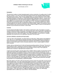
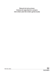
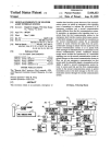
Acronym ICOM = Integrated
Circuit Oscillator Module.
The operating frequency
determining element is the
quartz crystal inside the
ICOM. Shown here is the Tx
“2C” ICOM circuitry with a
crystal, compensator,
oscillator and two frequency
modulators; phase and
direct. The latter is used as
the compensator.
A temperature change
causes the crystal to change
in frequency, such as in a
mobile environment. To
keep it on frequency in this situation a compensation circuit consisting of two thermistors and some
resistors are set up in a voltage divider arrangement with supply from pin 1. With temperature changes
they switch in or out changing the voltage across a varactor diode (reverse bias if you will), which is
paralleled across the crystal, making it a “direct” frequency changer, AKA direct FM. However, this is not
an audio circuit in stock configuration.
All 5Cs and 2C have compensation built-in. Only the 5C’s compensation voltage goes out on pin 4. ECs
do not have any compensation, therefore, depend on compensation voltage from a 5C ICOM via its pin 4.
Besides stability, if there’s no compensation voltage they won’t net on frequency (5-7 KHz low).
Note: the OEM drawing is a little vague to say a 2C’s compensation voltage does not connect to pin 4
(except during factory testing). However, the 5C does, and this line on pin 4 is what drives the other ECs.
The audio input on pin 3 phase modulates the (second) varactor diode, which is in series with the crystal
and oscillator transistor. Since it’s PM, won’t be good for flat audio. The FM will, with some modifications.
The (FM) compensation circuit also can interfere with good (linear) audio so should be to be removed.
There are reputable people that will differ with this practice, so take this into consideration for your own
project. Most SRG stations are located at a temperature controlled site, so compensation is not a major
concern especially, if you add the appropriate temperature compensation capacitor to keep the crystal on
frequency within the .002 PPM spec. (that’s .0002 %)
There were three versions
researched to modify the
ICOM for direct FM
however, only version one
is most successful and
covered here. For 5C and
2C ICOMs remove the
separate (little) daughter
board inside the ICOM. To
greatly improve the FM-AF
TLP change out the input
resistor from the 56K to
1K. Change out the RF
filter cap from .01uf to 100
pf to prevent top end rolloff.
For the 2C you will need to
reconnect the pin 4 run.
Next, you will need a bias
source to run the EC.
5
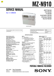
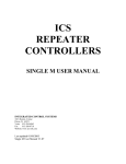
Bias source:
If you have a spare transmitter ICOM (EC, 5C, 2C, etc.) remove the screw on top and pry open tabs on
the bottom edges of the ICOM.
Note: The screw will be either a Torx-6 or a “allen” (hex) type; size of
.050” (about 3/64). The Torx bit (or Torx driver (red handle) (as shown in the image) can be found on the
Inter-net as well as the .050” hex driver (yellow handle). Shown is the Xcelite part LN-20; 050 (Mouser
Elect # 578-LN20).
The PCB has several components including the (fundamental) oscillator, crystal, modulation and
compensation circuits. Strip the necessary components off it to isolate pins 1, 4 and 5. The Author chose
to remove all components for display and research reasons.
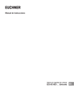
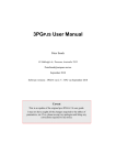
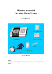
Next, install a 10K trim pot. 10 or 20 turn type is
best. The holes used that line up with the pot’s
leads put it in a great spot for a tool to access
through the top of the can, when completed. You
also will need two jumpers on the ICOMs board; pin
1 to the top of pot (10v) and pin 4 to the wiper. The
low side of the pot goes to ground. One (minor)
twist; the adjustment will be reversed; CCW to
increase the bias voltage. We will now call this the
“bias ICOM”. Shown here is the EC ICOM in
position one and the bias ICOM in eight. Note the
easy access hole for the bias pot adjustment.
6
The Author was concerned about the PCB pins touching
the can. Using a piece of laminate plastic prevents this.
Make a notch for the rivet area.
Assemble the bias ICOM can and screw and install it in
any position other than the channel’s ICOM (which would
be F1). In the picture the bias ICOM is in the F8 slot.
Inject a test tone to deviate the transmitter fully (in the
amateur world is 5 KHz). Tune the bias for best
symmetry. You will have to reset the input test tone to verify its good at TTL. Typical bias will be 3.41v.
The response should easily make 8Hz ~ 10 KHz.
Receiver ICOMs:
Like the transmitter side, the receiver side EC ICOMs will need bias voltage to be on frequency. The two
main differences is the bias in on pin 2 and it will be 5.0v instead. From a spare, old receiver ICOM, strip
the parts, add two jumpers and the trim pot as shown. Adjust the pot for the 5v output on pin 2.
7
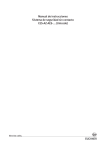
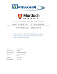
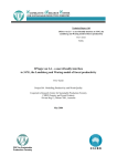
Receiver:
The receiver is easier for flat audio. For start,
the audio will be picked off the discriminator of
U602. There are active components (such as
Q601) to bring the level up however,
complicates maintenance. For example,
adjusting R608 would change the TLP. To
simplify, the “FM DET MTR” audio is used,
which is from the discriminator, going through a
few connections then appearing on P904-3.
From pin 3 there’s no outside connection from
this point, so a jumper was installed from the
IF/audio board’s P904-3 to the oscillatormultiplier board’s P903-3 (old Rx F3 select line).
From this point it goes out the (old) F3 Rx line
and ends up at J2-3 on the back of the chassis.
The Rx F3 line is not planned to be used, plus
there appears no components on this line to
affect the audio, making this an ideal circuit for
audio output. Optionally, remove the bottom
cover and shield to gain better access to the
points to the jumper.
The (stock) TLP for this point was found to be
too low (around –25) therefore, R607 value is
changed from the 180K to 1K. This brings the
TLP up to a (typical) –16 which the (external)
cor/af board can handle this level (see separate
document on that device).
Next, the receiver’s cor (signaling) can be
obtained from the (stock) CAS from U603 that appears on P904-9 and ends up at J1-13 on the back of
the chassis. Using unused lines is a “cleaner” way instead of the audio and cor wires running through the
chassis.
Below is a close-up of that jumper showing it from the discriminator point. One nice feature (over the
Motorola) is the little shield is not soldered to the board, making removal a snap.
8
Transmitter control option:
The OEM drawings can cause some confusion with parts identification. For example, on the exciter
board, Q114/Q113 ID is grouped together (with the slash) on the schematic diagram. Also, on the board
layout drawing, the first significant digit of these parts is deleted. For example “Q114” becomes Q14. SRG
will use the latter part identification.
The receiver’s ICOM “runs” continuous but the transmitter does not, causing the latter crystal aging to be
longer. This can be changed. The Station control card on the shelf provides both continuos and keyed
10v. On the exciter board the continuos 10v appears on pin 7 of P902, while the keyed 10v appears on
pin 12. Continuos 10v supply inputs Q13 at its emitter. Keyed 10v to R56 turns on Q13; its collector goes
low and turns on Q14. Q14’s collector is the (switched) output which goes to a 5v regular and also
filter/divider R54, C55 and R59. This goes to the Tx ICOM’s pin 2; activating RF out on the same pin and
paralleled to the RF filter, FL101, then to the multiplier stages.
To make the transmitter’s ICOM run continuously, lift one side of R54 (lead towards ICOM pins) and
install a common diode in series with its anode on pin 1 of Y4. The diode lowers the supply on pin 1
“close” to what the OEM circuit did (9.6v). Q13 and the 5v regulator will be isolated from this and still
function as a keyed circuit, allowing normal transmitter control while keeping the ICOM live all the time.
The Author choose not to do this option as of 2014.
9
Receiver signaling options:
There are two thoughts to the process:
•
Conventional, stand alone repeater with linking. This would be the configuration most amateur
repeaters are set up, with its receiver audio & PTT going into a (on site) repeater controller and it’s
output going to the associated (on site) transmitter, including any IDer audio. This would be a singlesite station, with possible linking into another repeater, group or service. Also, both the repeater
control and repeater audio cards would be used on the station shelf.
•
Flat audio, 4-wire drop-in station, with full-time link support. This is the normal configuration for SRG,
with its receiver audio & PTT downlinked to another station, typically a (distant) HUB (repeater) or
MCP, with the uplink (return) audio & PTT from that HUB or the MCP. Therefore, the 2-meter station
is not stand-alone; the audio (and carrier) path goes through the distance end. Only the regulator card
would be used in this case. Many of the OEM circuits and idea are discarded and bypassed.
Local monitor audio:
(for conventional stations)
For SRG packages much of the audio, COR PL decoder and PLI paths are custom set up, ignoring most
of the OEM circuits used in the station. However, for a conventional station (not flat audio) it would be
helpful for you to know some points. For remote site receivers, you need to have three outputs:
•
•
•
Audio, to feed a conventional controller and finally the associated transmitter.
“COR” (RUS) to drive the controller and/or repeater control card, etc.
“PLI”; (CG decode output) an indication there is a valid tone (CTCSS) on frequency to control the
station’s audio and PTT circuits. Obviously, for receivers on carrier squelch this last item won’t apply.
The main point is, for a simple way the on-site technician can hear the receiver’s local audio (speaker) for
checking interference and/or dynamic sensitivity checks, while not affecting the normal station’s operation
(i.e. keying the station’s transmitter to check for receiver desense.
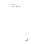
For stations that don’t use the repeater
control card take out the jumper H41H42. This prevents the CG output
(signal) from providing a “low” at the
receiver’s P904-7 line (which controls
U603 and U604 there).
For stations that do use the repeater
control card the above cut won’t work.
This is because the PLI (CG output) goes
into the control card on pin A3. This
signal goes back out of the control card
on A6, to mute the receiver’s COR and
local audio. The best place to change this
was found to make a cut on the run from
J904-7 and H42. The run-cuts are then
tinned in this image for easy identification
only.
This prevents any CG signal from muting the local speaker. Therefore, the local speaker will always be on
carrier squelch. This also prevents the local or remote PTT switches or the regulator card (H18 area) from
muting the local speaker audio as well. However, there still is another issue, which is addressed on the
next page.
10
Repeat audio “AND Squelch”:
In times of carrier squelch operation (no interference) is simple to operate a repeater. In times of
interference (or other reasons) tone control will complicate the repeater’s control however, is doable.
The repeater PTT can be an “AND squelch” via the repeater control cards “OR” gate of CR12 and CR8
from the inputs of RUS and CG Detector voltage, respectively. However, the (conventional) repeat audio
will still be on carrier squelch (via Q13 on the repeater audio card). For a repeater with a significant long
tail and having some RFI this can be rather annoying to listen (until the PTT/carrier line drops out the
transmitter).
To fix this issue, the repeat audio also needs to be an AND squelch. Some explanation may help you in
this next task. The RUS is an open collector line with a pull-up; same as the CG decoder line. The latter
get’s its (10K) pull-up from R24 on the repeater control board. Therefore you can’t tie the line lines
coming into the board otherwise the R24 will raise the RUS line enough to keep the transmitter keyed
continuously.
The solution is a buffer circuit from the CG line to the RUS line. This allows the RUS to be “0” during
standby and to a “1” during activity with the CG decoder only controlling the “0” state, thus, creating an
“AND squelch”. Both lines have to go high to activate the PTT circuits.
Therefore, a simple dual transistor buffer
was installed on the System board’s P935,
which provided 4 spots:
•
•
•
•
A power source (10v) (pin 1)
A ground (A-) (pin 5)
A CG decoder signal (H41)
A place to control the RUS line.
Shown here is a convenient location to tiemount the two transistors and resisters.
Remember: These design ideas are for a
conventional repeater only. For SRG (flat)
equipment the next section applies.
11
COR/AF Board mount:
This board is an independent, custom board designed by the Author for many different interface
applications for SRG projects. In this case it takes both the RUS and CG decoder lines to make an AND
squelch either for the PTT, audio or both. The PTT and audio lines then will drive a downlink transmitter.
This task is to mount the cor board on a station card. The
line driver (remote audio) card was selected
(19A129924G3) because several were available and the
stock card would not be used in any SRG projects. First,
remove all the components except for the front pots.
There’s about 120 components and 5 jumpers typically,
so this will be labor intensive. The (daughterboard) pins
in the center can be removed; however, in most cases
this destroys the runs as well. An alternative is to cut
them off, flush with the board. The board on the left is
the stock, right with the components removed. The pins
are yet to be cut or removed in the picture below.
The OEM repeat audio and repeat control cards are not
used in this case (only the reg/control card is used).
F1 control (single frequency):
This repeater is set up for single-frequency
operation (F1) for both transmit and receive.
OEM strapping is done in two separate
locations and may be difficult to find without a
detailed search of the drawings and their
functions. Both are tied “low” via “A -“. A- is the
same as ground. Each jumper location is:
For the transmitter, is located inside Tx-Rx
“drawer” unit and inside the exciter section.
There’s a jumper on the back of J933 pin 8 to
12
pin 4; the latter being ground. It’s usually a short, white wire sometimes behind the blue (F1) wire and
may be hard to find.
For the receiver, is located inside the Tx-Rx
“drawer” unit and on the “system” board, A901.
There’s a jumper between points H47 and H48;
the latter being ground (right image).
More difficult circuitry:
Another circuit that’s hard to trace physically (wires) and in the OEM manual, are a couple of jumpers for
the “VOL SQ HI” circuit. Inside the drawer unit (Tx-Rx chassis) the receiver outputs this circuit on P904
pin 11 which plugs into J904 pin 11 on the System board. The System board’s run takes this over to J951
pin 8. (J951 is the closest jack to the chassis edge). P951 pin 8 plugs into this. Within the short wiring
hardness a white wire takes this to J932 pin 16. P7 plugs into J932. P7, pin 16, has a little bare jumper
(DA) on the outside going to its pin 17 (left image). This goes back inside to J932 on pin 17, now. A white
wire takes this to the top of the squelch adjustment pot (located in the chassis of the drawer unit). There
is also a short (yellow) jumper (called DA) from J932 pin 17 to 3 for other functions (right image). Wow,
what a wild circuit !
13
Below is the schematic locations (from the OEM manual) for the Rx F1 jumper, the “VOL SQ HI” jumper
DA and the discriminator jumper to be added.
The OEM manual shows most of the connection lines between various components of the station, such
as the system board, motherboard, etc. You will need to do a lot of back - and – forth tracing since these
lines appear on several pages of the manual. The Author provided a simplified block and level set of
diagrams that are supplements to this document. It greatly clarifies the circuits to someone just starting
out understanding this radio.
This material may be copied in complete form only for non-profit purposes, such as for the knowledge for
the amateur radio service, with AK2O credited as designer. For other arrangements please contact the
Author.
Copyright: AK2O 2014
14