1
USOO5444433A
United States Patent [191
Gropper
[54] MODULAR EMERGENCY OR WEATHER
ALERT INTERFACE SYSTEM
[76] Inventor:
Daniel R. Gropper, 9908 Dale Ridge
Ct., Vienna, Va. 22181
[21] Appl. No.: 207,537
[22] Filed:
Mar. 7, 1994
[51]
Int. Cl.6 ............................................ .. G01W 1/00
[52]
US. Cl. .................................. .. 340/601; 340/539;
[58]
Field of Search ................. .. 340/601, 539, 309.15;
[56]
455/382, 38.4, 67.7, 57.1; 379/37, 38, 39, 40,
41, 48, 49, 50, 51; 381/119
References Cited
Patent Number:
Date of Patent:
5,444,433
Aug. 22, 1995
weather alert interface system between a ?rst communi
cation system, on which an emergency alert signaling
tone is transmitted to indicate the occurrence of an
emergence condition, and a second communication
system, different from the ?rst communication system.
In operation, an emergency alert signaling tone is re
ceived from the ?rst communication system by the
emergency alert interface system which causes a prere
Lee ...................................... .. 379/51
Meadows ..
.. 348/460
corded alert message to automatically be transmitted on
the second communication system for an adjustable
number of cycles wherein the audio from the prere
corded alert message is mixed with the audio from the
second communication system so as to permit both
audio messages to simultaneously be transmitted on the
second communication system. Additional features
taught herein include the transmission of a subaudible
signaling tone on the second communication system to
permit listeners on the second communication system to
6/1977 Singleton ..
. 45 5/ 57.1
6/ 1985 Shapiro ............................... .. 379/ 38
9/1992 Sakamoto et al. ................ .. 381/119
system until the subaudible signal is transmitted and the
ability to permit a second communication system lis
340/309.15; 455/57.1; 379/37
U.S. PATENT DOCUMENTS
3,626,098 12/1971
3,975,583 8/1976
4,031,467
4,524,243
5,148,491
[11]
[45]
OTHER PUBLICATIQNS
The “Bearcat Alert” receiver-User’s manual-1994.
ACC Reporter Controller Owner’s Manual p. 8-4, Apr.
1 987.
?lter out all non emergency communication on that
tener to access and link and the ?rst communication
system to the second communication system to permit
immediate access to the alert message on the ?rst com
munication system through the second communication
system.
Primary Examiner——John K. Peng
Assistant Examiner-Julie Lieu
[57]
ABSTRACT
This invention relates to an automatic, emergency or
38
0 6
‘
/
IX RAIIO TRANSIIT
ANTHIIA
/4
INS FGIECAST OFFICE
20 Claims, 5 Drawing Sheets
US. Patent
Aug. 22, 1995
Sheet 1 of 5
5,444,433
N
f
4 5x,53
<25;
_
\5
i25 7!2:
w22x3E25:
K00
3a: oma:
v\
ma:agma.
_| L
._
um
_
_
=32%5:: =2:
:2(wv
9555w;5%
US. Patent
Aug. 22, 1995
Sheet 2 of 5
mssnow e
5 comm
VOLTAGE
common //
1mm“
5,444,433
FLIP-FLOP
[
0-0UTPUT
i RESET
BOUTPIJT
sues
mm: 1
‘
V
| snouun
l
AUDIO [56 H“I050 Hz smswAvrz,1
8 AMA /\ mm?
D
5 L/UUWWUUUU
E
<!
TIME -—-—>
5s
.
1* | g _
6
US. Patent
Aug. 22, 1995
|_9' FROM ALERT ———1
CYCLE TIMER
Sheet 4 of s
‘ 5,444,433
4A
(+5'ro+|5v)
/
'4
J
'2
OUTPUT PULSES +5‘,
RI
_?.>_.._
'
'
ALERT
IESSAGE
U-mtLLtz 0v STORAGE
l8]
R2‘
HI ,4 M2
'
CHARGE on 0|
0|
0|
(pf)
.
Hz
I
H2
H2
H2
KHz
FREQUENCY
I0
KHz
KHz
US. Patent
Aug. 22, 1995
Sheet 5 of s
s,
2:8%.95a?” .
“w” “W4NR5
\
E|
“<2
Z
2
E
2WEE
.8:
,433
1
5,444,433
2
spheric Administration’s (NOAA) Weather Radio, as
MODULAR EMERGENCY OR WEATHER ALERT
INTERFACE SYSTEM
the ?rst communication system, and numerous second
ary communication systems, including, but not limited
to, school, of?ce building or hospital public address
systems, public utility and public safety (such as ?re and
FIELD OF THE INVENTION
An object of this invention is to provide an automatic
police) radio systems, commercial land mobile commu
nication systems, commercial AM or FM broadcast
radios, marine band radio communication systems, ama
teur radio communication systems or just about any
emergency alert interface system between a ?rst com
munication system and a second communication system
to automatically alert listeners on the second communi
cation system to check for an alert message on the ?rst l0 other type of communication system.
communication system.
NWS forecast of?ces around the United States con
Another object of this invention is to create a reliable,
tinuously broadcast taped weather messages which are
inexpensive, totally automatic and modular emergency
repeated every four to six minutes and are routinely
alert interface system between the two communication
revised every one to three hours, or more frequently if
15
systems.
Another object of this invention is to alert listeners on
the second communication system of the alert issued on
the ?rst communication system while simultaneously
not disrupting communication in progress on the second
communication system.
needed. Most of the stations operate twenty-four hours
a day. Under a January 1975 White House policy state
ment, NOAA Weather Radio was designated as the sole
20
Another object of this invention is to create a simple,
versatile, modular alert interface system which will
easily connect to existing second communication sys
government operated radio system to provide direct
warnings into private homes for both natural disasters
and nuclear attack. This capability is to supplement
warnings by sirens and by commercial radio and televi
sion. Due to the expense, unreliability and ineffective
ness of warning sirens, many siren systems around the
tems without much, if any, modi?cation to the second
country have been deactivated.
25
communication system.
The NWS operates about three hundred and eighty
Another object of the invention is to incorporate
(380) NOAA weather radio stations. Approximately
subaudible signaling tones to remotely activate receiv
ninety (90%) percent of the nation’s population is
ers on the second communication system upon activa
within listening range of NOAA Weather Radio broad
tion of the emergency alert interface system by the ?rst
casts.
A similar network of about ?fteen stations using
communication system.
the same frequencies broadcast continuous weather
Another object of the invention is to provide a means
information across much of southern Canada.
for using the emergency alert interface system on sec
NOAA Weather Radio broadcasts are made on one
ond communication systems, including radios, public
address systems, commercial AM or FM broadcast
radios, public safety (?re and police) communication
35
of seven high band FM frequencies ranging from
162.400 to 162.55 megahertz (MHz). These frequencies
systems and other communication devices such as cellu
are not found on the average home radio now in use.
lar telephones.
However, a number of radio manufacturers offer special
weather radios to operate on these special frequencies,
with or without the emergency warning alarm.
Another object of this invention is to create an emer
gency alert interface system in which the alerting agen
During severe weather, NWS forecasters can inter
rupt the routine weather broadcast and substitute spe
cial warning messages. The forecasters will transmit an
alert tone of 1050 Hertz (Hz) to activate specially de
cies, such as the National Weather Service, need to
make no changes in their equipment or procedures cur
rently in use to activate the emergency alert interface
system.
signed NOAA weather radio warning receivers tuned
Another object of this invention is to create an emer
gency alert interface system wherein listeners on the 45 to special NOAA weather radio frequencies. A single
alert tone is normally transmitted for up to thirteen (13)
second communication system need to make no changes
seconds for selected watches and warnings.
Special alert receivers, upon detecting the NWS sin
to their communication receiving equipment to be
alerted to the emergency condition.
Another object of this invention is to permit the sec
ond communication system operator to select and
gle alert tone, are usually con?gured to activate an
audible siren alarm in the radio and/or open the squelch
of the radio to let the listener hear the alert message
change the warning message on the emergency alert
interface system to meet the system’s speci?c needs.
Another object of this invention is to permit listener
and/or ?ash a signaling light, usually a light emitting
diode or LED, to alert the listener that an alert has been
Another object of this invention is to save lives and
issued.
The radios can be set in a latching mode meaning that
the siren or light will flash or sound continuously until
property through the noti?cation of the public of the
manually reset, or be set in an automatic reset mode,
issuance of a weather or emergency warnings when
which will reset shortly after the alert tone is detected.
Each of these alert modes has disadvantages. If the
radio latches in the siren mode, the siren will sound
continuously until the radio is manually reset. If the
owner of the radio is away, the siren will be sounding
unnecessarily for hours or even days. The usefulness of
the alert is usually for a short period of a few minutes
access to the alert message on the ?rst communication
system through the second communication system.
they are outside and away from shelter, but still have
access to a second communication system.
SUMMARY AND BACKGROUND OF THE
INVENTION
55
Although this invention may be used as an interface
between numerous emergency ?rst communication 65 for a tornado or thunderstorm, up to a few hours for a
systems, a primary application of this invention is be
winter storm. Therefore, since the majority of impor
tween the United States Government’s National
tant alerts are useful for only a short time frame, it is not
Weather Service’s (NWS) National Oceanic and Atmo
useful having the alert sound continuously for many
3
5,444,433
hours or days. The siren tends to aggravate pets. The
4
tance of the alert requires a response time often mea
sured in minutes, the fact that the alert was issued an
latching light is not audibly aggravating, but since these
radios have no time stamp, the listener will not know
lier. Finally, the NWS tests the system at least once per
unknown time (possibly hours or days) before being
discovered makes the warning close to meaningless.
The time when a weather alert becomes extremely
week. Therefore, a latching alert system would latch in
urgent is when people are away from their usual shel
when the alert was issued, one minute or one day ear
the alert setting at least once a week until reset.
ters and are out in their cars, boats, airplanes or are
If the system is not set in a latching mode, the listener
will most likely miss the alert if the listener is not near
simply outside. In these circumstances, a weather alert
radio sitting at home or in the of?ce is essentially worth
less.
Even if the weather radio is in an attended of?ce,
the radio at the time an alert or test signal is issued.
These operational problems tend to drastically de
crease the effectiveness of the alerting system. These
such as the principal’s of?ce of a school, it still takes a
defects will tend to cause the listener to turn off or
knowledgeable person to understand the meaning of the
ignore a potentially lifesaving time critical warning,
weather alert alarm, to find out the details of the alarm
which in the case of a tornado may be less than ?ve
minutes.
and to issue the appropriate warning over the public
address or other alerting system. Often the knowledge
NOAA Weather Radio broadcasts can usually be
heard as far as forty miles from the NWS transmitter
site. The effective range depends on many factors in
able person, for example the principal or secretary, will
be away from the radio or will be busy with other mat
ters when the alarm sounds thereby creating a poten‘
cluding the height of the broadcasting antennae, the 20 tially critical delay in relaying the weather alert mes
average surrounding terrain, quality of the receiver and
sage to the relevant public.
type of receiving antennae. As a general rule, listeners
The invention described herein overcomes the major
beyond the forty mile range need a good quality re
ity
of the above described handicaps in the NOAA
ceiver system if they expect to get reliable reception.
An outside antennae may be required in these fringe 25 weather radio alert system in a simple, inexpensive, and
reliable manner.
areas. To reliably receive NWS alerts, listeners more
Previously disclosed alerting systems, such as those
than 40 miles from the transmitting antenna often need
disclosed
in US. Pat. No. 4,031,467, entitled Alerting
to spend a signi?cant amount of extra money and effort
Process and System of Apparatus Therefor, usually
setting up an outside antenna. Many NOAA weather
radio listeners do not have the time, patience, money 30 require the use of expensive and dedicated special radio
receivers and additional trained personnel to activate
and/or expertise to put up such an antenna and accord
the
special alerting system. For the reasons set out
ingly may miss the warning message. Many dwellings
above, these are the very defects in the current alerting
do not permit outside antennas.
system.
Another problem is that the reliability of the radios
available to the general public is at best moderate due to
a number of economic and engineering factors. The
Some repeater controllers have the capability of
being modi?ed to provide a weather alert feature. The
weather radios are required to be moderately priced by
the requirement that the price needs to be low enough
so that people will consider buying a special radio. If
the price were extremely high, fewer people would be
able to afford this important communication warning
RC-85 Repeater Controller, manufactured by Ad
vanced Computer Controls, Inc. of Santa Clara, Calif,
system. Since the receivers are required to be moder
ately priced in an effort to encourage wide distribution
thereof, the engineering sensitivity and selectivity tends
40
Owner’s Manual, page 8-4, describes, in general terms, a
weather alert feature. While the described weather alert
feature will transmit an alert on the second communica
tion system in response to an NWS tone alert, this sys
tem suffers from many defects.
The RC~85 alert message is transmitted once every
to be similarly moderate.
45 ?fteen (15) seconds. This period is non adjustable. It
was found in trials that this was too often and was ex
The invention taught herein overcomes many of the
tremely annoying to the listeners. The invention de
above described radio reception problems by placing a
scribed herein permits the user to adjust alert message
weather radio receiver at a central location with good
timing cycle. From experience this was found to be
reception, for example at a transmitter site. These sites
optimally approximately once per minute.
are usually in high locations such on top of large build
The audio mix level between the alert message audio
ings or mountains. Since only one installation needsyto
level and the second communication system audio is not
be set up, it becomes cost effective to invest in a special
independently adjustable on the RC-85. In practice, the
directional or yagi antenna to increase reception, if
needed. Additionally, where applicable law permits the
RC-85 alert message level effectively blocked commu
retransmission of weather radio on other frequencies, 55 nication on the second communication system during
the second communication system effectively acts as a
each alert message, which occurred each 15 (?fteen)
repeater for the NWS weather radio thereby increasing
seconds during the alert cycle. For the alert system to
the effective range and coverage of the NWS transmit
be accepted by the users of the second communication
ter without further cost or equipment. Instead of being
system, it must not interfere with potential emergency
limited to approximately a forty mile radius coverage 60 communication on the second communication system.
from the NWS transmit antenna, the new area of cover
The feature of setting the audio level of the alert mes
age becomes the second communication system’s area
sage at a level to not interfere with ongoing communi
of coverage!
cation is not disclosed in the controller manual. Addi
From experience, it has been found that most people
tionally, the feature on the controller to be used for the
who purchase weather radios locate them in their home 65 weather alert is primarily for a latching repeater site
or in an unattended office where the listener may not
alarm which is meant to be loud to catch listener’s atten
?nd out about an alert for hours or days after the alert
until that person returns to the radio. When the impor
tion.
tion without respect to permitting ongoing communica
5
5,444,433
The RC-85 alarm, once activated, can only be deacti
vated by the use of a usually secure code usually held
only by control operators of system. In most cases, the
control operators will not be available to reset the sys
6
is designated 6. It will be understood that the described
emergency alert interface system 2 will work with any
type of warning device which can be detected, whether
it emanates from the NWS or from any other agency on
tem in the event of a malfunction or a test of the system. 5 any means including hardwire and radio.
The proposed invention permits the alert to be instantly
reset through the push of a button which can be conve
niently (physically or functionally) located near the
users to permit the system to readily be reset as needed.
For clarity, the remainder of this speci?cation will
relate to NWS/NOAA weather radio.
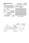
The emergency alert interface system 2 has a number
of components. They include a commercially available
Although not disclosed in the description of the
alarm function, it is possible to preset the duration of the
NWS/NOAA weather alert radio receiver 8 having an
alert signal detector 10 and a receive antenna 36. The
site alarm as a controller function, but it is not possible
alert signal detector 10 should be capable of detecting
the alert signal from the ?rst communication system,
generally 38, and producing a voltage logic output
(usually +5 volts or 0 volts) in response thereto. It will
to set the repetition cycle which is ?xed at ?fteen (15)
seconds.
The RC-85 has a limited digital prerecorded vocabu
lary and does not have the ability to record special alert
messages such as those containing subaudible signaling
be understood that the weather alert radio receiver 8
and alert signal detector 10 can be any past, present or
tones or discrete alert messages to alert management of
future communications technology capable of receiving
the alert without causing undo concern to the listening
and detecting an alert signal and producing a logic
public. In practice, these customizing features are ex~ 20 output in response thereto. The standard weather alert
tremely important to making the alert system accept
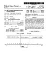
tone is a sine wave having a 1050 Hertz frequency. FIG.
6 is a representative drawing of an electrical signal, as
viewed on an oscilloscope, having one section of audi
ble audio 56 and one section of a modulated tone 58
The alert feature on the RC-85 is one subfeature of a 25 with a frequency of 1050 Hz.
repeater controller which usually costs near one thou
The logic output of the alert radio receiver is input
sand dollars. It would not be realistic to purchase a
into an alert cycle timer 12. The alert cycle timer 12
able to listeners by not causing harmful interference to
ongoing communication on the second communication
system when the alert sounds.
repeater controller only to receive weather alerts. The
proposed invention likely has a cost of a small percent
age of the cost of a repeater controller thereby making
the proposed invention more likely to be adopted and
used by the public.
governs the length of time that the emergency alert
interface system is in the alert mode, as opposed to
being in the standby or ready mode. The alert cycle
timer 12 may be of any conventional type of timer that
can be activated by a logic signal, now known or here
inafter invented. As shown in FIGS. 2 and 3A, an inex
similar controllers are not an acceptable substitute for
pensive and reliable alert cycle timer 12 can be based on
the proposed invention. The terse description in the 35 a 555 (or equivalent) timer integrated circuit wired in a
controller’s owner’s manual does not suggest the impor
standard and known monostable one shot mode. In
tant features of the instant invention which have been
practice, con?guring the alert cycle timer 12 with an
found in practice to be the features that make the inven
R-C circuit with a one megaohm potentiometer 78 and
tion useful and acceptable to the listening public.
a 470 microfarad capacitor 80 will permit an adjustable,
In view of the above disadvantages, the RC-85, and
BRIEF DESCRIPTION OF THE DRAWINGS
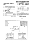
FIG. 1 is a system block diagram of the emergency
alert interface system.
FIG. 2 shows 555 speci?cations and an internal block
diagram of the 555 integrated circuit.
FIG. 3A shows the basic monostable timer circuit.
FIG. 3B shows the resistor/capacitor circuit reset
cycle for the 555 timer in the monostable mode.
approximately ten (10) minute, alert timing cycle upon
receiving a simple logic signal from the detector 10. A
ten minute cycle, per alert, has been found to be the
upper end of optimum for the alert cycle. FIG. 3B
shows the resistor/capacitor circuit reset cycle for the
45 555 timer in the monostable mode.
For ease of servicing and for users to readily deter
mine the status of the emergency alert interface system
2, status light emitting diodes 40 and 20 (LED) may be
connected to the input and output of alert cycle timer
555 integrated circuit.
50 12. LED 40 is connected to the input of alert cycle
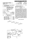
FIG. 4B shows the resistor/capacitor reset cycle for
timer 12 and shows that the alert system is powered up
FIG. 4A shows a basic astable circuit based on the
the 55S timer in the astable mode.
FIG. 5 is a schematic of a simple play/record circuit
for the ISD 1000A DVR integrated circuit and the
and ready to respond to an alert message. LED 20 is
attached to the output of alert cycle timer 12 and shows
that the system is in the alert mode. LED 20 will turn
logic interface to the second communication system. 55 off when the alert cycle timer 12 resets.
FIG. 6 is a representative drawing of an electrical
A power shut down switch 24 for the alert cycle
signal, as viewed on an oscilloscope, having one section
timer 12 should be included in the circuit between the
of audible audio and one section of a modulated tone
alert detector 10 and the alert cycle timer 12. This
with a frequency of l050 Hz.
switch should be remotely operable in the event that the
alert
system malfunctions. The switch can be any
DESCRIPTION OF THE PREFERRED
known type or hereinafter invented including relays
EMBODIMENT OF THE INVENTION
and semiconductors. This is extremely important where
FIG. 1 is a system block diagram of the emergency
the alert system is placed at a transmitter site which may
alert interface system 2. Block 86 in FIG. 1 represents
be a great distance from the listeners. By shutting down
the components in FIG. 1 on which greater detail is
power to the alert cycle timer 12, power is also instantly
shown in FIG. 5.
shutdown to the alert message timer 14 and the alert
A representative NWS forecast of?ce is designated 4
tone for the second communication system 16 thereby
and the NWS/NOAA weather radio broadcast antenna
effectively and ef?ciently disabling the entire emer
7
5,444,433
gency alert system 2. The emergency alert system 2 is
con?gured to permit the passive passage of audio from
the second communication system 22 through the emer
gency alert system 2 even when the emergency alert
system 2 is powered down in order to maintain the
reliability of the second communication system 22 de
spite the status of the emergency alert system 2.
A 555 type integrated circuit can produce an output
logic voltage and will also act as a source of output
current. Using these features of the 555 integrated cir
cuit, the output of the alert cycle timer 12 is used as a
current source input for the alert message timer 14 as
well as a current source for the alert tone for the second
communication system 16.
8
It has been found that a digital voice recorder (DVR)
chip is very effective for recording alert message 18.
Many such chips are available and this technology is
advancing forward at a dramatic rate. Any such chip
now known or hereinafter invented in which approxi
mately twenty (20) seconds of warning message may be
placed upon and which will run thorough one message
each time a logic signal is sent from alert message timer
14 can be used in emergency alert interface system 2.
For reference, FIG. 5 is a schematic of a simple play/~
record circuit the ISD (Information Storage Devices)
DVR integrated circuit called the ISD 1000A which
may be used in the herein disclosed invention.
FIG. 4 shows a basic astable circuit based on the 555
It is preferable to have the ability to record and
change alert message 18 onto the DVR through press
integrated circuit. FIG. 3B shows the resistor/capacitor
reset cycle for the 555 timer in monostable mode.
ing record button 60 and placing audio into electret
microphone 44 connected to the DVR board. This
The alert message timer 14 is set up in a commonly
known astable multivibrator mode. The alert message
enables the control operators to record custom mes
sages for speci?c listening audiences. In commercial,
timer 14 is powered up only during the time the alert 20 amateur radio and public service (?re, police, ambu
cycle timer 12 is active. The alert message timer 14
generates a logic pulse to the alert message 18 inte
lance, utility etc.) a two second audible alert tone fol
lowed by the words “Check for weather alert on 162.55
grated circuit to start the transmission of a message
Megahertz” has been found to be an understandable and
cycle. It will be understood that any continuously cy
ef?cient alert message. The message may be customized
cling logic activated message recording device, such as 25 for various services as needed. For example, acknowl
a tape recorder, may be used in this circuit. A manual or
edging that the system is tested at least once a week, it
remote alert cycle timer 12 reset switch 42 should be
may be preferable to have a more discrete alert message
included in the system to reset the timer as needed,
such as “Manager, check for code 99” where it is impor
especially during the weekly test of the system. If the
tant to not unnecessarily frighten or panic speci?c lis
555, or equivalent, timer is used, the standard timer reset
switch con?guration may be used as is shown in FIG.
3A.
The alert message timer 14 may be a 555 (or equiva
teners, such as shoppers in a department store. In such
an instance, a manager or a clerk would be trained to
check the NOAA weather radio to determine if the
situation was a test or an actual emergency that would
lent) integrated circuit with the circuitry to permit ap
need to be tactfully publicly announced. The versatility
proximately a one (1) minute timing cycle during the 35 of this emergency alert interface system 2 is the ability
time when alert cycle timer 12 is activated. Use of a one
to adapt itself for numerous situations to be useful with
megaohm potentiometer 82 and a 47 microfarad capaci
out being unnecessarily annoying or frightening.
tor 84 in a common astable multivibrator format as
It has been found that a battery back-up is important
shown in FIG. 4A will permit an approximate one min
to preserve the readiness of the DVR recorded mes
ute cycle, which has been found to be optimum. In this
sage, as well as to avoid false alerts due to momentary
manner, the coordination of the ten minute cycle of the
power failures. Placing a twelve volt lantern battery 46
alert cycle timer 12 and the one minute alert message
in parallel with the power supply where the positive
timer 14 permits the optimum output of an alert message
terminals of the lantern battery and the power supply
generated on the second communication system 22 of
are fed through a diode junction has been found simple
once per minute for the ten minutes following the alert 45 and cost effective. In this manner, when the power
signal on the ?rst communication system 12.
supply drops below twelve volts due to a power failure,
The alert tone 16 for the second communication sys
the twelve volt battery maintains the logic and integrity
tem 22 is generated for the entire time (usually ten min
of the DVR, and the weather alert radio. Since the
utes) that the alert cycle timer 12 is active. In this man
weather alert radio runs on nine volts instead of twelve
ner, any communication during the ten minute alert
volts, a simple nine volt ?xed regulator may be used to
period also has a subaudible alert signaling tone 16 as
convert twelve volts to nine volts to power the radio.
part thereof. In this manner, any listener who has the
During each alert cycle, three audio signals are
equivalent of tone squelch set on his or her radio re
mixed. They are (l) the audio from the second commu
ceiver and who hears the receiver unsquelched, even
nication system 26 by mix adjustments 30; (2) the alert
during the approximately forty (40) seconds of each
tone for the second communication system 16 by mix
minute that the alert message 18 is not “playing” will
adjustment 50; and the (3) alert message 18 by mix ad
immediately know that a tone alert has been issued on
justment 52. The relative balance of these three audio
the ?rst communication system 12. This is especially
levels is critical to the successful operation of the inven
important where there is a time critical warning such as
tion. The audio from the second communication system
for a tornado.
26 is set- at the normal level for effective communica
Subaudible alert tone 16 may be generated by any
tion. The alert tone for the second communication sys
known or hereinafter invented means including a spe
tem 16 is set at about twenty percent (20%) deviation so
cial CTCSS tone generating board such as one pro
as to reliably open squelches, but not so loud as to be
duced by Communications Specialists. These boards are
noticeable to the listeners. The alert message 18 audio
commonly commercially available in a multitude of 65 level is to be set at a level so as to mix into the back
frequencies. Such boards have a level adjust potentiom
ground of any ongoing communication on the second
eter to set the subaudible level to the correct overall
communication system 26, but not so high as to interfere
output level.
with ongoing communication. A ?fty percent (50%) to
5,444,433
seventy percent (70%) deviation level of the alert mes
sage 18 relative to the audio level of the second commu
nication system 26 has been found effective. The com
bined and adjustably mixed audio is designated 48 and
are input into the second communication system 22 and
transmitted from the second communication system
antenna 32. Any type of audio mixer now known or
hereinafter invented in which the relative amplitude
input levels are independently adjustable may be used
with the invention taught herein.
To be completely automatic, the emergency alert
interface system 2 must also key the second communica
tion system transmitter 22 when the alert message 18 is
10
ing with any primary communication on secondary
communication system 22. In practice, it has been found
that setting the rebroadcast to be completely and auto
matically overridden by audio on second communica
tion system 22 to be acceptable since the rebroadcast
information is a continuous tape which will repeat
every few minutes and since this information is also
available from a number of media sources.
From the above, it is apparent that this interface
system is extremely simple to construct, is extremely
versatile, and can easily be installed in a multitude of
communication systems without much modi?cation.
Such a system would be extremely useful if placed at
playing. A simple method to accomplish this coordina
the transmitter of a public safety communications sys
tion is to derive the necessary logic 28 from the output
tem such as police, ?re or ambulance, or public utility
voltage of alert message 18 digital voice recorder. Fur
communications system such as telephone, electric, or
ther reference is had to FIG. 5 an logic interface section
gas company. This system will enable the weather ser
28 having the legend, “To Xmitter Press To Talk Logic
vice to automatically alert the members of these vital
Line Second Communication System.” The reference
public services of a impending weather alert without
line shows a connection from the press to talk logic line 20 interfering with two way communications already in
28 of second communication system 22, to the collector
progress. An emergency alert interface system 2 may
68 voltage of transistor 01. This voltage is normally
easily be placed on amateur radio repeaters, AM and
held at logic high (normally + 5 V) by Vcc 62 through
FM commercial transmitters, marine band, land mobile,
47K resistor R8 64. When 01 is energized, through Ol’s
aviation, and any other conceivable communication
base 66, the logic output 28 connection to Ol’s collector 25 systems to automatically alert listeners to an impending
68 is brought to a logic low state (0 V). 01 can be ener
weather emergency which may directly affect the lives
gized manually, through playback switch 54 S1 and
and property of listeners.
47K resistor R5 70, or automatically, through the out
It will be apparent that numerous modi?cations of the
put voltage provided by Sp+72 (speaker+), when
above invention may be made without departing from
audio is present at the speaker output, as applied
the nature, intent, or spirit of the invention as claimed
through 47K resistor R7 74. Thus, when 01 is ener
herein.
'
gized, collector 68 voltage at 01 drops from 5 V to 0 V
What I claim is:
and press to talk logic line 76 for second communication
1. A weather or emergency alert interface system
system 22 is activated to permit alert message 18 to
comprising:
automatically be retransmitted on second communica 35
a. a ?rst communication system;
tion system 22. Second communication system 22 is
b. a signaling tone transmitted on said ?rst communi
automatically unkeyed when alert message 18 has ?n
cation system;
ished playing as a result of the voltage dropping to zero
c. a receiver, tuned to said ?rst communication sys
at SP+72 at the end of each play cycle.
tem, further comprising a detector to detect said
From experience in actual high RF environment
signaling tone, wherein said detector generates a
repeater sites, it is imperative that the commercially
available weather alert radio intended for home use be
encased in a RF resistant metal box to prevent desense
and intermodulation from other strong, nearby trans
mitters which will potentially interfere with the recep 45
tion by that receiver of NCAA Weather Radio. Using
normal radio engineering techniques, it may be prefera
ble to take the commercially available weather alert
radio out of its plastic housing and to mount the pc
board directly in a metal RF resistant metal enclosure. 50
Many commercial radio services, including the ama
teur radio frequencies, may permit the retransmission of
NCAA Weather Radio broadcasts directly on second
communication system 22. This may be accomplished
by connecting speaker outputs of the NOAA weather
alert radio 8 to second communication system 22 auxil
changed logic level output in response to detecting
said signaling tone;
. an alert cycle timer, having a controlled logic level
output, wherein said alert cycle timer is activated
by said changed logic level output from said detec
tor, and wherein said logic level output of said alert
cycle timer changes for a set period after said alert
cycle timer has been activated by said changed
logic level output from said detector;
e. an alert message timer, having a controlled logic
level output, wherein said alert message timer is
activated by said changed logic level output from
said alert cycle timer, and wherein said logic level
output of said alert message timer periodically
pulses at preset intervals during the period when
said alert cycle timer has been activated;
iary input. Any presently or hereinafter invented
f. an audible prerecorded alert message, having an
method may be used to initiate the retransmission of
NOAA weather radio over second communication
adjustable outgoing audio level, wherein said audi~
ble prerecorded alert message plays a complete
message cycle in response to each logic pulse from
said alert message timer;
system 22, generally designated 34. These may include 60
a listener operated signal, such as DTMF, or another
signaling tone or sequence. A timer should be placed in
line to automatically terminate the rebroadcast after a
set period of time. Means should also be provided to
permit listeners to manually terminate the retransmis 65
. a second communication system for transmitting an
outgoing message, further comprising means for
adjusting the audio level of said outgoing message;
h. means for mixing said adjustable outgoing audio
sion. Finally, the rebroadcast should be set to be in a
levels of said audible prerecorded alert message
subservient role to any other ongoing communication
and said outgoing message on said second commu
on second communication system 22 to avoid interfer
nication system in such a manner as to enable listen
11
5,444,433
12
ers to said second communication system to simul
-
10. A weather or emergency alert tone interface sys
taneously hear both audio messages;
i. means, electronically initiated by the activation of
tem, as recited in claim 1, wherein said alert message
further comprises an outgoing subaudible signaling alert
said alert message timer, for automatically keying
tone.
the transmitter of said second communication sys
11. A weather or emergency alert tone interface sys
tem, as recited in claim 1, wherein said second commu
tem during the period when said audible prere
corded alert message is playing; and,
j. means for transmission of said audible prerecorded
alert message, mixed with said second communica
nication system is a maritime radio frequency.
12. A weather or emergency alert tone interface sys
tem, as recited in claim 1, wherein said second commu
nication system is a public address system.
tion system audio, on said second communication
system, when said second communication system is
keyed, for the duration of the activation of said
alert cycle timer in time periods determined by said
alert message timer.
13. A weather or emergency alert tone interface sys
tem, as recited in claim 1, wherein audio information
from said ?rst communication system may be accessed
by listeners on said second communication system
through said second communication system.
2. A weather or emergency alert tone interface sys
tem, as recited in claim 1, wherein said ?rst communica
14. A weather or emergency alert tone interface sys
tem, as recited in claim 1, wherein said second commu
tion system is radio.
3. A weather or emergency alert tone interface sys
tem, as recited in claim 1, wherein said second commu
nication system is radio.
nication system is a public safety communication sys
tem.
20
4. A weather or emergency alert tone interface sys~
15. A weather or emergency alert tone interface sys
tem, as recited in claim 1, wherein said second commu
nication system is a public utility communication sys
tem, as recited in claim 1, wherein said alert cycle timer
tem.
is an electronic timer.
5. A weather or emergency alert tone interface sys
16. A weather or emergency alert tone interface sys
tem, as recited in claim 1, further comprising a listener
activated alert cycle timer reset switch.
tem, as recited in claim 4, wherein said alert cycle timer
is based on a 555 timer.
6. A weather or emergency alert tone interface sys
17. A weather or emergency alert tone interface sys
tem, as recited in claim 1, wherein said ?rst communica
tion system is NOAA weather radio.
tem, as recited in claim 1, wherein said alert message
timer is an electronic timer.
30
18. A weather or emergency alert tone interface sys
7. A weather or emergency alert tone interface sys
tem, as recited in claim 1, wherein said second commu
tem, as recited in claim 6, wherein said alert message
nication system is land mobile radio.
timer is based on a 555 timer.
19. A weather or emergency alert tone interface sys
8. A weather or emergency alert tone interface sys
tem, as recited in claim 1, wherein said audible alert
tem, as recited in claim 1, wherein said signaling tone
has a frequency of 1050 hertz.
message is electronically recorded.
20. A weather or emergency alert tone interface sys
tem, as recited in claim 1, wherein said audible prere
9. A weather or emergency alert tone interface sys
tem, as recited in claim 8, wherein said audible alert
message is electronically recorded on a digital voice
recorder.
corded alert message may be changed by the system
control operator.
*
45
55
60
65
*
=l=
*
*
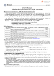
UNITED STATES PATENT AND TRADEMARK OFFICE
CERTIFICATE OF CORRECTION
PATENT NO. : 5 ,444 ,433
DATED
I August 22, 1995
|NVENTOR(S) : Daniel R. Cropper
It is certi?ed that error appears in the above-indenti?ed patent and that said Letters Patent is hereby
corrected as shown below:
On the title page, under item [56] Reference Cited: line 13,
Insert —-—Attorney — Daniel R. Gropper——
Signed and Sealed this
Second Day of January, 1996
Arrest:
6%“ W
BRUCE LEI-{MAN
AIIESIiHg Officer
Commissioner of Parents and Trademarks