1
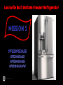
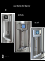
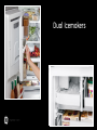
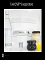
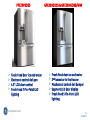
2012 French Door Refrigerator Louisville Built Bottom Freezer Refrigerator Large Stainless Steel Dispenser GE GE Profile GE Cafe Industry First Hands Free AutoFill Industry First Advanced filtration with Filter in the Door Temperature Controlled Drawer with Colored LED Lights Drop Down Tray Space-Saving Icemaker Dual Icemakers Showcase LED Lighting TwinChill™ Evaporators Winning Features TwinChill™ Showcase LED Lighting Space-Saving Icemaker Drop Down Tray Hands Free AutoFill Advanced Filtration with the Filter in the Door Temperature Controlled Drawer Large Sleek Dispenser 3 Freezer Drawers PFE29PSDSS Fresh Food door ice and water Electronic control deli pan 4.3” LCD door control Fresh Food 7 Pin-Point LED lighting GFE29HSDSS & GFE29HGDBB/WW Fresh Food door ice and water 2nd icemaker in the freezer Mechanical control deli damper Segment LED door display Fresh Food 5 Pin-Point LED lighting 13 5/4/2012 IMPORTANT SAFETY NOTICE The information in this presentation is intended for use by individuals possessing adequate backgrounds of electrical, electronic, & mechanical experience. Any attempt to repair a major appliance may result in personal injury & property damage. The manufacturer or seller cannot be responsible for the interpretation of this information, nor can it assume any liability in connection with its use. WARNING To avoid personal injury, disconnect power before servicing this product. If electrical power is required for diagnosis or test purposes, disconnect the power immediately after performing the necessary checks. RECONNECT ALL GROUNDING DEVICES If grounding wires, screws, straps, clips, nuts, or washers used to complete a path to ground are removed for service, they must be returned to their original position & properly fastened. 14 5/4/2012 GE Factory Service Employees are required to use safety glasses with side shields, safety gloves & steel toe shoes for all repairs Dyneema® Cut Resistant Glove Plano Type Safety Glasses Electrically Rated Glove and Dyneema® Cut Resistant Glove Keeper Prescription Safety Glasses Safety Glasses must be ANSI Z87.1-2003 compliant Steel Toe Work Boot Brazing Glasses 15 5/4/2012 16 5/4/2012 Fresh Food Section 17 5/4/2012 Upper Hinge Cover Removal Remove three ¼” screws from the top hinge cover Open both fresh food doors to 90˚ Move the cover slightly forward to release the tabs from the hinges and slide back. 18 5/4/2012 Fresh Food Dispenser Door Removal Remove the hinge cover assembly and lay the cover back onto the cabinet to access the top hinge screws, wiring and water tubing. Cabinet water tubing conduit 19 5/4/2012 Disconnect the Water Line Remove the tube clamp from the hinge Disconnect the top side of the quick connector located at the rear of the cabinet, 15” down from the top. 20 5/4/2012 Door Removal Pull the water line from the cabinet conduit. Disconnect the wiring connectors and ground wire. Remove the three 3/8” screws from the top hinge. Lift the hinge bracket up to release and remove from the door. 21 5/4/2012 Door Removal Open the door to a 90 degree angle from the case and lift to remove the door from the lower hinge bracket. 22 5/4/2012 Fresh Food Door Stop The door stop is held in place by two T20 screws 23 5/4/2012 Fresh Food Door Closer The door closer is removed by first removing the door stop, then the T20 mounting screw. 24 5/4/2012 Fresh Food Door Hinge and Closer The door closer has a spring loaded pin The right hinge bracket mounted to the case has an adjustable ¼” set screw so the fresh food doors can be leveled If the left door needs to be raised, shims will be available as a service part 25 5/4/2012 Freezer LED Lighting Two LEDs located in the bottom of the LEFT fresh food door illuminate the interior of the freezer when the freezer drawer is opened. The LEDs are snapped into a bracket that is accessed by removing a T20 screw. 26 5/4/2012 Articulating Mullion The articulating mullion is mounted to the left fresh food door The mullion uses a 12 VDC heater operated by the door control board. Operation is based on room temperature and humidity. 27 5/4/2012 Room Ambient Thermistor The room air thermistor is located in the cover on the top of the cabinet, this thermistor is used to set the duty time of the sweat heaters and adjust the cooling system based on room temperature. 28 5/4/2012 RJ45, Ambient Thermistor and Humidity Board The ‘Zigbee™’ board is located on the top of the case in the hinge cover. It contains the sensor to monitor the humidity level of the room and the RJ45 connector for computer diagnostics. J 4 Ambient Thermistor Humidity Sensor R J 4 5 29 5/4/2012 Fresh Food Cabinet Interior 30 5/4/2012 Fresh Food Cabinet Interior PFE29 MULLION STRIKE FRESH FOOD THERMISTOR COLD AIR DISCHARGE AIR DUCT WATER FILTER MULTIPLE PINPOINT LEDS ELECTRONIC CONTROL DAMPER AND FAN ADJUSTABLE RIGHT LOWER HINGES SHIMS USED ON LEFT 31 5/4/2012 Fresh Food Cabinet Interior GFE29 WATER FILTER MULLION STRIKE FRESH FOOD THERMISTOR COLD AIR DISCHARGE AIR DUCT MECHANICAL DAMPER MULTIPLE PINPOINT LEDS EVAPORATOR COVER ADJUSTABLE RIGHT LOWER HINGES SHIMS USED ON LEFT 32 5/4/2012 Fresh Food Showcase Pin-Point LEDs The Pin-Point LEDs are in either a 5 or 7 LED series circuit. If one LED fails (but the LED’s resistor is still OK), that LED will not be lit while the others will be dim. When one LED fails completely, none of the LEDs will light. With a voltmeter, 5VDC – 20VDC can be read across the terminals of the completely failed LED assembly. To remove the LED, pry up at the rear and slide to rear to release the tab. Each LED has a 2-pin connector for easy replacement. 33 5/4/2012 Air Flow 34 5/4/2012 Fresh Food and Freezer Thermistors The Fresh Food thermistor is located in the ceiling and the freezer thermistor is located on the right hand side wall. 35 5/4/2012 Thermistor Replacement The thermistor grille uses an alignment tab to ensure proper grille placement. The grille also uses two snap tabs to lock it into the liner. 36 5/4/2012 Thermistor Replacement To replace the air thermistor; remove the thermistor from the grille and cut the thermistor wiring as close to the thermistor as possible. Strip the outer insulation from the thermistor case harness back 1”. Strip the two internal wires back 3/16” for splicing. GE Factory Service Technicians are required to always wear cut resistant gloves prior to commencing the repair. 37 5/4/2012 Thermistor Splicing Prepare the replacement thermistor (WR55x10025) by cutting the wiring 4” back from the thermistor and strip the wires back 3/16”. Using two WR01X10466, splice the wiring. After the splices are complete, fill the bell connectors fully with WR97X163 silicone grease. Note: Service kit coming with heat seal connectors WR01X10466 38 5/4/2012 Thermistor Splicing Snap the thermistor into the grill and place excess wiring into the thermistor pocket, then snap the grille back into the liner taking note of the alignment pin. 39 5/4/2012 Fresh Food Fan Testing The fresh food fan is located at the base of the fresh food air duct. The fresh food evaporator cover must be removed to access the fan, but can easily be checked at the electrical connector. Remove the right vegetable bin. Removing the electrical cover (A) will expose the electrical connector (B) for testing with a multi-meter. 1. LOW SPEED = 2700 RPM* The fresh food fan operates at 3 speeds 2. MEDIUM SPEED = 3000 RPM* 3. HIGH SPEED = 3300 RPM* Note: Fan speed range of 1500–4100 RPM is acceptable B A FAN color code: RED – 12vdc+ BLACK – 12 VDCYELLOW – PWM SPEED BLUE – RPM FEEDBACK * Values are approximate and preliminary 40 5/4/2012 Deli Pan Cover Removal Remove both vegetable bins and deli pan. It is not necessary to remove the upper glass shelves. Remove the Phillips screw on each side of the deli pan cover. 41 5/4/2012 Deli Pan Cover Removal Slide the front part of the deli pan cover forward Disconnect the electrical connector at the left slide assembly 42 5/4/2012 Deli Pan Board On Cover The deli pan board sends the customer setting to the main board to control the pan temperatures based on the deli thermistor value. Temperature is controlled by opening or closing the deli damper, varying fan speeds and turning on a 5 watt heater as needed. The consumer presses a single button (tactile switch) to scroll through the settings. LEDs on the control will light the selected mode. White LEDs will also light the pan area. Colored LEDs will light the pan area on the Café models. L e d s L e d L e d L e d L e d s Tactile Switch 43 5/4/2012 Deli Pan Set Points The selections that show ‘OFF’ are not available at the fresh food set points on the left. Example is meat is not available when fresh food temp is set to 39˚F or higher. 44 5/4/2012 Deli Pan Thermistor 45 5/4/2012 Deli Pan Slide Removal Remove the screws from both of the deli pan slide assemblies. Pull the assembly forward to disengage the tab from the wall liner post. 46 5/4/2012 Mechanical Deli Damper (GFE29 only) The mechanical deli damper is also located on the fresh food evaporator cover and is accessed the same way. The damper is operated by a lever in the left slide assembly. Moving the lever up closes the damper while moving it down opens it. C L O S E O P E N O P E N C L O S E 47 5/4/2012 Fresh Food Evaporator Cover Remove the fresh food fan connector cover by pressing down at the upper right, then slide it straight out. P R E S S Remove 5 Phillips screws. 1 screw is behind the connector cover. 48 5/4/2012 Deli Pan Fan, Heater and Damper Pull up on the fresh food evaporator cover and lay it forward. Disconnect the fan and damper assembly connector. Remove the gasket and Styrofoam retainer, then remove the assembly from the evaporator cover. DAMPER HEATER Fan speed range is 3000 – 6000 RPM FAN color code: RED – 12vdc+ BLACK – 12 VDCYELLOW – PWM SPEED BLUE – RPM FEEDBACK * Values are approximate and preliminary 49 5/4/2012 Fresh Food Fan Removal Disconnect the motor harness connector. FAN color code: RED – 12vdc+ BLACK – 12 VDCYELLOW – PWM SPEED BLUE – RPM FEEDBACK Pull the Styrofoam cover out from the lower left corner and remove. Slide the fan assembly forward and out of the fan mounting bracket. 50 5/4/2012 Fresh Food Evaporator Thermistor The fresh food evaporator thermistor is mounted to the suction line, its sole purpose is to monitor the evaporator temperature for defrost control. 51 5/4/2012 Fresh Food Defrost Heater The fresh food defrost heater is located at the bottom of the evaporator between the rows of coils, attached to the end plates. It is a 165 watt glass tube radiant heater. The heater can be dismounted by removing the center support. Bend the tabs on the end plates inward then pull it down and forward. There is a drip shield mounted just above the heater. There is a 140˚F safety thermostat in the neutral line of the heater circuit. Note: The evaporator is shown inverted for illustration. Bend tab inward 52 5/4/2012 Freezer Interior 53 5/4/2012 Freezer Interior GFE29 ICEMAKER FREEZER FAN UPPER BASKET SLIDES ICE BOX AIR RETURN UPPER BASKET SLIDES LOWER BASKET SLIDES FREEZER THERMISTOR LOWER BASKET SLIDES Note: PFE29 interior is the same but does not have freezer icemaker 54 5/4/2012 Freezer Drawer Removal Open the drawer and remove three 3/8” screws from the left and right hand slides. 55 5/4/2012 Freezer Drawer Removal Lift the drawer front off of the slides – releasing the two tabs from the slide tab slots. GE Factory Service Technicians are required to lift with the legs and not the back. 56 5/4/2012 Freezer Drawer Adjustment The adjustment knob(s) can be rotated to change the horizontal drawer plane. 57 5/4/2012 Freezer Fan The freezer fan is mounted to the freezer evaporator cover and uses a grille to direct the air flow. The freezer fan will operate at 3 speeds with RPM feedback to the control: 1. LOW SPEED = 2200 RPM* 2. MEDIUM SPEED = 2400 RPM* 3. HIGH SPEED = 2500 RPM* Note fan speed range is 1500 – 2900 RPM* The fan connector can be accessed for multi-meter checks by removing only the grille. * Values are approximate and preliminary 58 5/4/2012 Freezer Fan Grille Removal Insert a screwdriver into the slot and pry down to raise the tab and release the grille. The grille will now slide down to disengage the top tabs. 59 5/4/2012 Freezer Fan Removal SLIDE RIGHT Flex the tab at the lower right to release the fan from the evaporator cover. Slide the fan to the right to disengage the left retainer tabs. Disconnect the electrical connector. 60 5/4/2012 Ice Box Air Flow RETURN AIR SUPPLY AIR RETURN AIR 61 5/4/2012 Ice Box Fan The ice box fan is located at the top left rear of the freezer, above the evaporator. The ice box fan circulates air into the left fresh food door ice box via ductwork foamed into the case. The fan has 3 possible speeds, depending on the ice box cooling temperature and is controlled by the main board. 1. LOW SPEED = 1500 RPM* 2. MEDIUM SPEED = 1700 RPM* 3. HIGH SPEED = 1800 RPM* Note fan speed range is 1000 – 2500 RPM* Top tabs Bottom tabs FAN color code: RED – 12vdc+ BLACK – 12 VDCYELLOW – PWM SPEED BLUE – RPM FEEDBACK Removal: Disconnect the electrical connector. Note: This connector contains the freezer evaporator thermistor connections Remove the ¼” mounting screw. Gently flex the top or bottom tabs to release the fan from the ice box air supply duct. * Values are approximate and preliminary 62 5/4/2012 Ice Box Fan Removal The upper freezer compartment divider must be removed to access the evaporator cover. Remove the 2 retainers by flexing them outward and pulling toward the front to release. Slide the divider backward to disengage from the retainer mounted to the ceiling. GFE29- icemaker must be removed (see icemaker removal) 63 5/4/2012 Evaporator Cover Removal Remove the 2 Phillips screws at the top of the evaporator cover. Push the cover up to release the tabs at the bottom, then pull the bottom outward. Disconnect the fan connector. NOTE: The freezer fan does not have to be removed from the cover 64 5/4/2012 Evaporator and Ice Box Fan Evaporator Thermistor Ice Box Fan Freezer Evaporator 65 5/4/2012 Freezer Evaporator Thermistor The freezer evaporator thermistor is mounted to the suction line. The purpose of the thermistor is to monitor the evaporator temperature for defrost control. 66 5/4/2012 Freezer Defrost Heater The freezer defrost heater is located at the bottom of the evaporator between the rows of coils, attached to the end plates. It is a 420 watt glass tube radiant heater. The heater can be dismounted by removing the right end and center support. Bend the tabs on the end plates inward then pull it down and forward. There is a drip shield mounted just above the heater. There is a 140˚F safety thermostat in the neutral line of the heater circuit. Bend tab inward Note: The evaporator is shown inverted for illustration. 67 5/4/2012 Machine Compartment 68 5/4/2012 Machine Compartment location – PFE29 INVERTER VARIABLE SPEED INVERTER COMPRESSOR FREEZER DRAIN TUBE 3-WAY VALVE CONDENSER FAN JELLY ROLL CONDENSER FRESH FOOD DRAIN TUBE ISOLATION VALVE 69 5/4/2012 Machine Compartment location – GFE29 RELAY AND OVERLOAD SINGLE SPEED COMPRESSOR 3-WAY VALVE CONDENSER FAN CONDENSER FREEZER DRAIN TUBE FRESH FOOD DRAIN TUBE ISOLATION, FREEZER ICEMAKER AND WATER DISPENSER VALVE ASSEMBLY 70 5/4/2012 Isolation Valve Water to the filter in the fresh food door is supplied by the isolation valve. The valve prevents the filter from being under constant house water pressure. The isolation valve is operated by the main control board. 71 5/4/2012 3-Way Valve ISOLATION VALVE The 3-way valve is located in the machine compartment between the compressor and condenser fan. 72 5/4/2012 3-Way Valve The 3-way valve is used to direct refrigerant flow. The valve has four different positions. They are referred to by the letters ‘A’, ‘B’, ‘C’ and ‘D’ A = Open to the Fresh Food and Freezer evaporators in series (refrigerant flows through the fresh food evaporator and then into the freezer evaporator). This is also called the (Home Position) B = Open to the Freezer evaporator only C = Open to both the Fresh Food and Freezer evaporators via the individual capillary tubes (this position is not currently used on these models) D = Closed to both Fresh Food and Freezer evaporators during the off cycle 73 5/4/2012 Freezer Only Cooling FREEZER FAN 74 5/4/2012 Fresh Food and Freezer Only Cooling FREEZER FAN FF FAN 75 5/4/2012 Condenser Fan Motor The condenser fan operates within a range of 1000–2100 RPM* To remove: Remove the rear access cover Disconnect the harness connector Pull the fan assembly toward the rear to disengage from the bracket * Values are approximate and preliminary FAN color code: RED – 12vdc+ BLACK – 12 VDCYELLOW – PWM SPEED BLUE – RPM FEEDBACK 76 5/4/2012 Operational Overview 77 5/4/2012 Normal Operating Characteristics Liner protection mode will turn on either the fresh food or freezer fan if the doors or drawer are open for more than 3 minutes* respectively. The condenser fan may run without the compressor operating* Dispenser will not operate with either fresh food door open* Fan(s) running without the compressor operating is normal. The variable speed compressor uses an inverter like previous variable speed. The compressor will start at high speed for 1 minute, then may change to a lower speed based on fresh food and freezer temperature. This may be perceived as a noise issue. There is a 20* second compressor delay on power up, but fans will start immediately if cooling is required. Compressor maximum run time is limited to 6* hours and the minimum compressor off time is 3* minutes. * Values are approximate and preliminary 78 5/4/2012 Normal Operating Characteristics continued If either fresh food door is open when the freezer drawer is opened, the freezer LEDs on the bottom of the left fresh food door will not come on. When either the fresh door(s) or freezer drawer is opened, the fans will turn off. The “box type” fans used on these models have different sound characteristics than fans used on previous models. Consumers may perceive this as a noise issue. On power-up, if the icemaker rake is not in the home position, the icemaker heater will turn on for 2 minutes before power is applied to the rake motor. Currently, this is only protected by the 210°F TCO on the mold.* THE MOLD CAN GET VERY WARM! The duct door is operated by a motor and the consumer may notice a very distinct motor sound when the duct door opens and closes. When either fresh food door is opened while dispensing, the dispenser will stop. After the door(s) are closed, the dispenser will not restart until the dispenser paddle switch is released and pressed again. * Values are approximate and preliminary 79 5/4/2012 Liner Protection Mode Liner Protection mode is controlled by two timers. Timer #1 monitors door-open time. A 3-minute door-open count begins when the door is opened. If 3 minutes elapse before the door is closed, the liner protection mode will become active. Once the door is closed, timer #1 resets and liner protection mode goes into standby. In standby, normal fan operation resumes and timer #2 begins a 3-minute door-closed count. If 3 minutes elapse without a door opening, liner protection mode will reset. If a door is opened within the timer #2 door-closed count, the remaining time in the door-closed count will be deducted from the timer #1 door-open count. 80 5/4/2012 Refrigerator Operation Both of these models operate in the following states: Pull Down Cooling Operation Fresh food Cycle defrost Pre-Chill Fresh Food Only Heated Defrost Fresh Food & Freezer Heated Defrost Dwell Post Dwell 81 5/4/2012 Pull Down Pull down occurs any time the refrigerator is plugged in and the freezer temperature is above 60˚F*. The 3-way valve moves to the ‘B’ position. Compressor start is delayed for 20* seconds. The compressor will start and run at high speed for 1 minute, then change to low speed (variable speed models only). The freezer fan will run at HIGH* speed. When the freezer temperature falls to approximately 12˚F*, the compressor will change to HIGH* speed and the 3-way valve will move to the ‘A’ position, delivering refrigerant to both the fresh food and freezer evaporators. The fresh food fan will begin running at HIGH speed and the freezer fan will continue to run at HIGH* speed. Compressor and fan speeds will vary with cabinet temperatures until the set temperature is obtained. After 6* hours of compressor run time (door openings not counted), both the fresh food and freezer will enter a heated defrost cycle. * Values are approximate and preliminary 82 5/4/2012 Cooling Operation When cooling is required, the main control board moves the 3-way valve to either ‘A’ position (supplying refrigerant to both fresh food and freezer evaporators) or ‘B’ position (supplying only the freezer evaporator), depending upon compartment temperatures. The compressor and fan(s) are delayed for 3* minutes before restarting. The compressor will start at high speed for 1 minute, then may change speeds depending upon the temperature of both the fresh food and freezer. When only the fresh food temperature is satisfied, the 3-way valve will move to the ‘B’ position (supplying only the freezer evaporator) to continue cooling the freezer. Fresh food cycle defrost will begin. When the freezer and fresh food temperatures are satisfied, the compressor and fans will turn off. The 3-way valve will move to the ‘D’ position, shutting off refrigerant flow to both evaporators to reduce refrigerant sounds. After the accumulated compressor run time (including door openings) has been reached, the unit will begin the defrost pre-chill cycle. ( 1 second of door opening = 100 seconds of compressor run time*) * Values are approximate and preliminary 83 5/4/2012 Fresh Food Cycle Defrost Fresh food cycle defrost occurs between heated fresh food defrost cycles to reduce excessive frost accumulations on the fresh food evaporator. During fresh food cycle defrost, the evaporator fan runs and there is no refrigerant flow through the evaporator. Fresh food cycle defrost does not use the fresh food defrost heater. Fresh food cycle defrost will occur any time the 3-way valve is moved from the ‘A’ position to the ‘B’ position. The fresh food fan will run at LOW* speed for 10* minutes, then cycle off if fresh food temperatures are satisfied. The fresh food cycle defrost does not occur when the compressor cycles off. * Values are approximate and preliminary 84 5/4/2012 Defrost Pre-Chill (Single and Variable speed compressor) After accumulating 96* hours of compressor run time (actual compressor run time and door openings), the operating system will enter pre-chill. Pre-chill will occur whether the last freezer defrost was normal or abnormal. Pre-chill time will vary from 10 to 60* minutes, depending on door openings and compartment temperatures during pre-chill. Any compressor run time prior to the beginning of pre-chill does not count in the pre-chill time. There is a 6* second delay after the compressor cuts off at the end of pre-chill before energizing the defrost heaters. The ice box fan will run at high speed whenever ice box cooling is needed during the pre-chill cycle. Pre-chill ends when either the maximum time expires (60 minutes*), evaporator pre-chill temperatures are met (-30F*) or freezer pre-chill temperatures are met (-10F*). * Values are approximate and preliminary 85 5/4/2012 Fresh Food Only Heated Defrost Fresh food only heated defrost occurs after 32* hours of compressor run time. Fresh food only heated defrost does not use a pre-chill cycle. Door openings are factored into the compressor run time. 1 second door opening = 100 seconds of compressor run time* Providing previous freezer or fresh food only heated defrost cycles were normal the freezer will defrost every 3rd* fresh food defrost. * Values are approximate and preliminary 86 5/4/2012 Freezer and Fresh Food Heated Defrost Following pre-chill, the heated freezer and heated fresh food defrost cycle is initiated where both heaters will be on at the same time. The 3-way valve will move to the ‘A’ position. The compressor will turn off. The condenser, freezer, fresh food, and ice box fans will turn off. The freezer defrost heater remains on until the freezer evaporator is 50˚F* (defrost termination temperature) or the maximum defrost time of 45* minutes is reached. The fresh food defrost heater remains on until the fresh food evaporator is 45˚F* (defrost termination temperature) or the max defrost time of 45* minutes is reached. If either the fresh food or freezer defrost heater’s on time exceeds the normal defrost threshold of approximately 20 minutes*, the defrost is considered abnormal. (Abnormal defrost forces both the fresh food and freezer into pre-chill after 6* hours of compressor run time -door openings not counted). During defrost, if power is interrupted, the refrigerator will restart in the dwell state if the freezer evaporator temperature is above 50˚F* (defrost termination temperature). After the defrost heaters turn off, the refrigerator will enter the dwell cycle. * Values are approximate and preliminary 87 5/4/2012 Dwell Cycle After both defrost heaters have cycled off, the unit will enter the dwell cycle. During the dwell cycle, the compressor and fans will remain off. The 3-way valve will move to the ‘A” position (both fresh food and freezer open) and remain there for the entire cycle. Dwell cycle will terminate after 10* minutes. At the end of the dwell cycle, the compressor run timer for adaptive defrost is reset to 0 hours and the refrigerator enters the post-dwell cycle. If power is interrupted during the dwell cycle and the freezer temperature is greater than 50˚F* (the freezer defrost termination temperature), the dwell cycle will start over. Note: Pull down will start if the freezer temperature is over 60°F * Values are approximate and preliminary 88 5/4/2012 Post Dwell Cycle Upon completion of the dwell cycle, the unit will enter the post dwell cycle. The 3-way valve will move to either the ‘A’ or ‘B’ position, depending upon whether the fresh food temperature is satisfied. The compressor and condenser fan will start, but the fresh food fan, freezer fan and ice box fan will remain off. Post dwell will end when the freezer and fresh food evaporators reach the post dwell exit temperature of -10˚F*, or the post dwell time of 10* minutes has expired. Upon exit of post dwell, the control system will now operate all cooling components by it’s logic and restarts the compressor run timer for adaptive defrost. * Values are approximate and preliminary 89 5/4/2012 Refrigerator Operation Summary Both of these models operate in the following states: Pull Down occurs when the refrigerator is powered up and freezer is above 60˚F Cooling Operation is the normal cycling of temperatures whether the last defrost was normal or abnormal. Fresh Food Cycle Defrost occurs when the 3-way valve turns off refrigerant flow to fresh food evaporator, but the freezer continues to cool. Pre-Chill occurs before freezer heated defrost. Fresh Food Heated Defrost occurs every 32 hours of compressor run time. Freezer Heated Defrost occurs every 96 hours of compressor run time. Dwell occurs after every heated defrost cycle. Post Dwell occurs after every dwell cycle. 90 5/4/2012 User Interface (UI) Controls 91 5/4/2012 Consumer Control Board (PFE29) Power & Communication Cup Switch ULTRASONIC SENSOR CONNECTORS FOR SENSOR FILL SOUND MODULE CONNECTOR 92 5/4/2012 Consumer Control LCD Models (PFE29) 93 5/4/2012 Consumer Control Board (PFE29) J4 J5 J3 J3 and J4 UPPER ULTRASONIC SENSORS J2 8- UNUSED 7- HOT H20 CUT SW 6- BOARD GND 5- 12VDC – J2 4- 12VDC + 3- HOT H2O LED 2- COMMUNICATION 1-UNUSED J4 J4 3- PADDLE SWITCH 2- PADDLE SWITCH 1- PADDLE SWITCH J5 LOWER ULTRASONIC SENSORS J7 SOUND MODULE J7 USB PORT A blinking green LED means the board’s DC power supply is on and operating. 94 5/4/2012 Consumer Control Temperature Adjustment Note the LCD customer control does not incorporate pads for temperature adjustment. To change compartment temperatures; touch the screen to wake the control up and change temperatures directly on the LCD screen. 95 5/4/2012 Consumer Control Temperature Controls Once ‘Temp Control’ is pressed, the adjustment screen will appear in the display. After adjusting to the desired temperature setting, press ‘Done’. The customer also has the option to change the displayed temperature from ‘°F’ to ‘°C’ from this screen. 96 5/4/2012 Consumer Control Dispenser Functions When the customer changes the dispenser functions, the display will show a short animation of the dispenser selection. 97 5/4/2012 Consumer Control Express Modes The ‘Express Modes’ option allows the consumer to turn on or off the ‘Turbo Cool’ and ‘Turbo Freeze’ functions. 98 5/4/2012 Consumer Control Precise Fill Options There are two modes of operation for water dispense. Standard ‘Precise Fill’ where the customer selects the amount of water and ‘Sensor Fill’ where the dispenser uses sensors to automatically fill the container to 90% full. In ‘sensing fill’, if no container is in the dispenser, the unit will not operate and notify the consumer. 99 5/4/2012 Hands Free AutoFill Industry First Hands free auto fill uses 3 ultrasonic sensors to measure the height, width, volume and shape of the container and will fill it to approximately 90% of its capacity. Ultrasonic sensors work in much the same way as back-up sensors used on many automobiles. This system is operated by the LCD control and the door control board. If there is a failure, the ultrasonic sensors and LCD control are replaced as an assembly. ULTRASONIC SENSORS 100 5/4/2012 Consumer Control System Settings When the consumer selects ‘Settings’ from the main screen, they can change or reset functions on the unit by scrolling through the screens. Reset the water filter Turn the icemaker on and off Turn the door alarm on and off Turn the control sound on and off Turn the cooling system on and off Change the temperature display to ‘F’ or ‘C’ Change the water dispenser from US Imperial to Metric 101 5/4/2012 Dealer Demo Mode Enter demo mode by pressing the ‘Lock’ and ‘Precise Fill buttons’ Exit demo mode by pressing the same buttons again or cycling refrigerator power. 102 5/4/2012 Dealer Demo Mode When Dealer Demo mode is active the following will occur: The compressor is off at all times. All heaters will be disabled. The icemaker(s) are turned off, but control will operate the display function. The fans and dampers may run if prompted by a user setting change. Opening the doors will not turn on the fans. Liner protection mode is active. The deli pan LED lighting will work normally. The deli fan will turn on at the heating mode speed. 103 5/4/2012 Dealer Demo Mode continued The deli pan settings will remain the same between door openings, as the set points are not reset. LED lighting will come on when the door or drawer is opened and stay at full power for 8 minutes if the door remains open. After 8 minutes, the LEDs will start to lower their intensity in a smooth transition over the next three minutes to 75% of their original power and remain there until the door(s) is closed. Closing and reopening the doors will restart the timer. The user can activate and deactivate the Door Alarm, Lock, Dispenser Light, and Reset Filter functions. The user can adjust the temperatures, but the cooling components will not operate. 104 5/4/2012 Dealer Demo Mode continued The user interface will display the actual compartment temperatures. Paddle and switch will not operate dispenser components if pressed. The Precise Fill feature can be selected and amount of water set, but water valve will not be activated. The Auto Fill can be set but will not activate water valve. An instructional video will play for 49 seconds and then return to the home screen. Turbo Cool and Turbo Freeze can be turned on and off, but no cooling action will be initiated. 105 5/4/2012 RJ45, Ambient Thermistor and Humidity Board The ‘Zigbee™’ Board is located on the top of the case in the hinge cover and monitors the ambient air temperature and humidity level of the room. This board also contains the RJ45 connector for the Brillion Technology ACM and computer diagnostics. J 4 106 5/4/2012 NewFI The ‘Zigbee™’ Board RJ45 connector allows the Factory Service technician to connect to the refrigerator to perform diagnostics on their laptop computer. The technician will be able to access error codes, current functions, operational history and operate loads for diagnosis. Remove the plastic plug to access. 107 5/4/2012 Sabbath Mode To enter or exit Sabbath mode; press the ‘Lock Control’ and ‘Dispenser Light’ buttons for three seconds. 108 5/4/2012 Sabbath Mode This feature was designed for use on the Jewish Sabbath Holiday. The Sabbath Mode feature will override typical interaction with the refrigerator. In Sabbath Mode the refrigerator will still cool normally, but will not respond to user’s actions. The LCD display will change to a screen prompting the consumer to enter or exit Sabbath mode. The display will show “Entering Sabbath Mode” or “Exiting Sabbath Mode” for 3 seconds and then disappears. The display will show “Sabbath Mode” while the control is in Sabbath mode. All of the displayed icons will be turned off. All of the sounds and tones will be turned off. The Sabbath mode will expire 76 hours after being activated by the consumer. 109 5/4/2012 Sabbath Mode continued The fan may or may not be running when the door is opened; however, this is not a result of the user’s actions. There is a delay on all control changes (fans and compressor) while the door is open. This includes any fan action as a result of doors opening. After a power outage, the refrigerator will power back up in the Sabbath Mode. The temperature settings of the refrigerator will remain as set prior to turning on Sabbath Mode and will return to those setting after Sabbath Mode is turned off. The door alarm is disabled. All of the button actions on the dispenser will be ignored by the control during Sabbath mode. The dispenser auto fill ultrasonic sensors for ‘Sensor fill’ are disabled. The water valve, auger motor and duct door motor are disabled. The icemakers are inoperative during Sabbath Mode. Door openings are not counted for adaptive defrost, so the user has no influence on the defrost process. The time between defrost cycles is fixed at 8 hours. The defrost heater termination is controlled by temperature. 110 5/4/2012 Sabbath Mode GFE29 UI FUTURE MODELS 111 5/4/2012 GFE29 LED User Interface Note: DC ground is extremely important on all control boards. On this model you could see ‘0’s moving in a racetrack pattern. 112 5/4/2012 GFE29 LED User Interface The Warmer/Colder buttons adjust the fresh food and freezer temperatures. The 7-segment display shows the “Actual Temp” or “Set Temp” of the fresh food and freezer temperatures. The Ice Maker button is toggled to turn on or off the fresh food door and freezer icemakers. “Ice Top” is the indicator for the fresh food door icemaker and “Ice Bottom” is the indicator for the freezer icemaker. The Turbo Cool button is toggled to activate the fresh food “turbo cool” and/or the freezer “turbo freeze” features. The fresh food 7-segment displays “tc” when in “turbo cool” and the freezer 7-segment displays “tf” in “turbo freeze” mode. If the water filter timer has expired, the “Replace Water Filter” display will be on. The Reset Filter button will reset the water filter timer. The Door Alarm button will activate and deactivate the door alarm. The Lock Control will prevent the consumer from interfacing with the refrigerator. The Dispenser Light button will turn on or off the dispenser light. The Water/Crushed/Cubed functions are exclusively linked by the system logic. Pressing one button selects the function and turns off the other two functions. The appropriate LED is lit when a function is selected. When the door switches are closed and the cup switch is depressed, dispensing occurs according to the selected function. 113 5/4/2012 Control Block Diagram DC Loads AC Loads Icemaker Door Control Board LED Lighting Sensors Icemaker Dispenser / Internal Temperature Control Board Main Control Board LED Lighting Deli Pan Control Board Sensors DC Loads AC Loads Inverter Main Control Board 115 5/4/2012 Main Control Board The main control board operates some or all of the following outputs depending on the model identification used: Freezer temperature control using compressor, fans and 3-way valve Fresh Food temperature control using compressor, fans, 3-way valve and damper (single evaporator models) Ice Box temperature control Deli pan control using the damper, fan and heater Variable fan speed control with RPM feedback for the condenser, fresh food and freezer evaporator, ice box and deli pan fans Freezer and fresh food evaporator defrost control Icemaker control for models with an icemaker in the freezer Control of the isolation water valve Control of mullion and ice port heaters based on external temperature and relative humidity Control of the fill tube heater for the icemaker located in the freezer Control of the interior LED lighting in the fresh food compartment 116 5/4/2012 Main Board Location MAIN CONTROL BOARD 117 5/4/2012 Main Control Board Block Diagram Zigbee Board convertible drawer fan Door Board Personality UI Board IM Arm Deli Pan Board IM Rake FZ Door Switch FF LH Door Switch FF RH Door Switch FZ Fill Tube Heater FF Fan DC Input Comm Comm FZ IM Heater AC Input FZ Evap Fan 5 V PWM Driver FZ IM Water Valve Cond Fan Ice Box Fan FZ IM Rake Motor Deli Pan Heater Feature / Deli Fan µP 3-Way Valve IM Supply Duct Port Heater µP Horizontal Mullion Heater Controller µP µP Air Duct Supply Heater 12 V PWM Driver Feature / Deli Damper FF/ Convertible Damper LED FF1 FF Defrost Heater Isolation Water Valve LED FZ Power Supply Inverter FZ Defrost Heater Input Vertical Mullion FZ Temp FF Evap Temp FZ Evap Temp Deli Pan Temp Ambient Temp Convertible Temp FZ IM Mold Temp L1 FF2 Temp Neutral GND FF 1 Temp %RH 118 5/4/2012 Main Control Board A blinking green LED means the board’s DC power supply is on and operating. J 1 4 J 1 3 J 1 2 J 1 1 J 9 J 1 0 J 8 DC J 7 J6 AC J5 J 1 J 2 J 3 J 4 119 5/4/2012 Main Control Board DC PIN 1 – ZIGBEE BUS PIN 2 – UI & DOOR BUS PIN 3 – ZIGBEE & UI BRD GND PIN 4 – DOOR BRD GND PIN 5 - 12 VDC ZIGBEE BRD + PIN 6 – 12 VDC UI BRD + PIN 7 – 12 VDC DOOR BRD + PIN 1 PIN 2 PIN 3 PIN 4 PIN 5 PIN 6 PIN 7 PIN 8 - 12VDC DELI + DELI BUS DELI BRD GND OPEN OPEN OPEN DELI THERMISTOR 5VDC DELI THERMISTOR PIN 9 - FF EVAP THERMISTOR 5VDC PIN 10 - FF EVAP THERMISTOR PIN 11 – 5VDC THERMISTOR OPEN PIN 12 – OPEN THERMISTOR PIN 14 – FF THERMISTOR 5 VDC PIN 16 – FF THERMISTOR J11 PIN 1 – COND FAN 12 DC + PIN 2 – COND FAN GND PIN 3 – COND FAN PWM PIN 4 – COND FAN RPM PIN 5 - MAIN BRD HTR PIN 6 – MAIN BRD HTR 12VDC+ PIN 7 – FINVERTER SIGNAL PIN 8 – INVERTER SIGNAL + PIN 9 - AMBIENT THERMISTOR 5 VDC+ PIN 10 – HUMIDITY 5 VDC + PIN 11 – AMBIENT THERMISTOR PIN 12 – HUMIDITY SENSOR SIGNAL PIN 13 – MUMIDITY SENSOR GND J9 J13 PIN 6 – FF LED s PIN 7 – FF LEDs + J14 PIN 8 - 3 WAY VALVE PIN 10 - 3 WAY VALVE PIN 12 - 3 WAY VALVE PIN 14 - 3 WAY VALVE PIN 16 - 3 WAY VALVE PIN 1 – 5VDC FZ THERMISTOR PIN 2 – FZ THERMISTOR PIN 3 – 5VDC FZ EVAP THERMISTOR PIN 4 – FZ EVAP THERMISTOR PIN 5 - THERMISTOR 5VDC PIN 6 – CNDVR PIN 7 – FZ IM THERMISTOR 5VDC PIN 8 – FZ IM THERMISTOR PIN 9 - RAKE SENSOR 5VDC PIN 10 – RAKE SENSOR PIN 11 - GND PIN 12 – FEELER ARM SENSOR * Indicates a wire in the connector at that location J12 J10 120 5/4/2012 Main Control Board DC continued: Future use PIN 1 – PIN 2 – PIN 3 – PIN 4 – PIN 5 PIN 6 – PIN 7 – PIN 8 – 12 VDC FZ FZN+ 12 VDC ICE BOX FAN + GND FZ FZN GND ICE BOX PWM FZ FAN PWM ICE BOX FAN RPM FZ FAN RPM ICE BOX J8 PIN 1 – 12VDC DELI FAN + PIN 2 – 12VDC FF FAN + PIN 3 – GND DELI FAN PIN 4 – GND FF FAN PIN 5 - RPM DELI FAN PIN 6 – RPM FF FAN PIN 7 – PWM DELI FAN PIN 8 – PWM FF FAN PIN 9 - DELI DAMPER PIN 10 – DELI DAMPER PIN 11 - DELI DAMPER PIN 12 – DELI DAMPER PIN 13 – OPEN PIN 14 – OPEN J6 PIN 15 – OPEN PIN 16 - OPEN MODEL ID * Indicates a wire in the connector at that location 121 5/4/2012 Main Control Board AC PIN 1 – LEFT FF DOOR SW PIN 2 – FZ DRAWER SW PIN 3 – RT FF DOOR SW PIN 4 - OPEN PIN 1 – HOT WATER INTERLOCK PIN 2 – AC GROUND PIN 3 – AC NEUTRAL PIN 4 – FZ DEFROST HTR PIN 5 – S SPD COMP PIN 6 – AC LINE 1 J1 J4 PIN 1 – ISOLATION VALVE PIN 2 – FF DEFROST HTR PIN 3 – ICE PORT HTR PIN 4 – MUL HTR PIN 5 – ICE DUCT HTR PIN 6 – DELI PAN HTR PIN 1 – FZ IM RAKE MTR PIN 2 – FZ IM HTR PIN 3 – FZ IM WTR VALVE PIN 4 - OPEN J3 * Indicates a wire in the connector at that location J2 122 5/4/2012 PFE29PS Main Board Schematic 123 5/4/2012 Door Control Board 124 5/4/2012 Door Control Board The door control board operates some or all of the following outputs depending on the model identification used: A/C outputs: Dispenser water valve Ice in door icemaker heater Ice in door icemaker rake motor Ice in door icemaker water valve D/C outputs Auger motor Duct door motor Recess / duct door heater Articulating mullion heater Door IM fill tube heater Ice box gasket heater Freezer LED interior lighting 125 5/4/2012 Door Control Board DC J3 PIN 1 - ICE BOX GASKET HTR PIN 2 - OPEN PIN 3 – FZ LED PIN 4 – ART. MULLION PIN 5 - FZ LED + PIN 6 – IM FEELER AREM SENSOR PIN 7 - DUCT DOOR MTR + PIN 8 – FLOW METER PIN 9 – RECESS HTR PIN 10 - OPEN PIN 11 – IM EJECTOR RAKE SENSOR PIN 12 – PADDLE SWITCH PIN 13 – FILL TUBE HTR PIN 14 – IM SENSOR GROUND PIN 15 – DUCT DOOR MTR PIN 16 - OPEN PIN 17 - 13VDC SUPPLY + PIN 18 – GEABUS (COMMUNICATION) PIN 19 – FLOW METER 5VDC PIN 20 – BOARD GOUND J5 PIN 1 – IM THERMISTOR PIN 2 – 5VDC PIN 3 – ICE BOX THERMISTOR PIN 4 – 5VDC PIN 5 – HOT WATER 1 PIN 6 – 5VDC PIN 7 - HOT WATER 2 PIN 8 – HOT WATER LED J3 J5 J 8 J 4 J 5 J 3 AC DC A blinking green LED means the board’s DC power supply is on and operating. * Indicates a wire in the connector at that location 126 5/4/2012 Door Control Board AC THIS WILL BE THE HEATER CONNECTOR FOR HOT WATER ON CAFÉ MODELS J8 J 8 PIN 1 – L1 A/C POWER SUPPLY PIN 2 – IM RAKE MOTOR PIN 3 – IM WATER VALVE PIN 4 – SWITCHED L1 AUGER INPUT PIN 5 - OPEN PIN 6 – AUGER MOTOR DC PIN 7 – DISPENSER WATER VALVE PIN 8 – AUGER MOTOR DC+ PIN 9 - IM MOLD HEATER PIN 10 - OPEN PIN 11 - OPEN PIN 12 - OPEN PIN 13 - OPEN PIN 14 - OPEN PIN 15 – OPEN PIN 16 – A/C NEUTRAL J 4 AC J4 J 5 J 3 DC * Indicates a wire in the connector at that location 127 5/4/2012 Door Control Board The dispenser board controls all AC and DC functions of the left hand fresh food door. This board is accessed at the top of the door after removing the three cover screws. J 8 J 4 AC J 5 J 3 DC 128 5/4/2012 PFE29PS Door Schematic 129 5/4/2012 13.6 VDC from Main Board Neutral L1 Switched Door Control Board Block Diagram L1 5 Volt Regulator Relay Relays Driver Door Fill Tube heater Relay 5 VDC Duct Door Motor Vertical Mullion Heater 13.6 VDC PWM Driver Ice Box gasket heater Recess / Duct Door Heater Controller Relay Door IM Water Valve Relay Door IM Rake Motor Relay Door IM Heater Relay Auger Motor Relay Main Board Relay Comm Dispenser Water Valve User Interface Input Ice Mold Thermistor Ice Box Thermistor 13.6 VDC Input 5VDC - Input IM Rake IM Arm Flow meter Cup Switch 130 5/4/2012 Dispenser Door Components 131 5/4/2012 Ice-in-Door Components Icemaker assembly Auger bucket assembly Auger motor Ice box door & gasket Air ducts and gaskets Water tank Water valve Flow meter Water filter Water filter manifold LCD/LED control assembly Duct door Duct door motor Ice funnel Ice & water paddle and switch assembly Door control board Sensor fill components Freezer drawer LEDs Articulating mullion Ice box thermistor 132 5/4/2012 Ice and Water in Door ICE BOX Pull lever out to open WATER TANK AND VALVE U P Lift slightly “up” to remove bucket 133 5/4/2012 Ice Box Door Gasket The gasket is easily removed by pulling the retainer out of the groove 134 5/4/2012 Ice Box Air Flow SUPPLY AIR RETURN AIR 135 5/4/2012 Ice Box Ports Ice Box air supply gasket Ice Box port gaskets are removed by pushing inward with a putty knife to release the retainer tab from the duct groove. Ice Box air return gasket 136 5/4/2012 Auger Bucket CCW FOR CRUSHED ICE CW FOR CUBED ICE 137 5/4/2012 Ice Box Components ICEMAKER ELECTRICAL COVER AUGER MOTOR Prior to working on the ice maker and associated components, GE Factory Service Technicians are required to properly lockout the unit and control the cord. That may require the application of the LOTO box, lock and tag. 138 5/4/2012 Ice Box and Icemaker Thermistors Both Ice Box and freezer icemakers contain thermistors Ice Box thermistor located in the electrical cover 139 5/4/2012 Icemakers The icemakers are similar to previous icemaker designs. Although similar, they are NOT interchangeable with each other (between door and freezer models) or any other service icemaker! PFE29/GFE29 ICEMAKER door mounted GFE29 ICEMAKER freezer mounted 140 5/4/2012 Icemakers The icemakers operate in much the same way as previous bottom freezer models with one significant difference: the icemakers are controlled by either the main control board or the door control board. The board inside the icemaker does NOT control operation. The icemaker in the door is controlled by the door control board. The icemaker in the freezer is controlled by the main control board. These boards will monitor the mold thermistor, rake and feeler arm sensors to operate the rake motor, heater and water valve. Like previous electronic icemakers, these new icemakers will run “Power On Diagnostics”, however, this will occur if the mold temperature is above 40˚F* rather than 50˚F like previous models. The thermistor has the same resistance value as previous electronic icemakers. * Values are approximate and preliminary 141 5/4/2012 Icemakers Power On Diagnostics If the icemaker thermistor temperature is 40°F (4.4°C) or higher* when the icemaker is connected to power, the control will perform a Power On test before entering the freeze cycle. The test consists of the following: Turn on the motor and rotate until it reaches home again Turn on the water valve for 1/2 second Turn on the heater for 1/2 second Verify that the feeler arm was in the “IN” and then in the “OUT” position Verify the motor was rotating by checking the motor was not in the home position and then returned to the home position Verify the motor does not remain on after being turned off Proceed to the freeze cycle * Values are approximate and preliminary 142 5/4/2012 Icemaker Sequence The normal icemaker sequence is to fill the mold with water, wait until the water is frozen, harvest the ice and then repeat the cycle. To accomplish this sequence, three cycles are defined: Freeze, Harvest and Water Fill. The Freeze cycle begins after a fill, when the mold temp drops below 32˚F* and will last for a minimum of 50 minutes*. After the Freeze cycle conditions have been met and the feeler arm is in the “out” position, a harvest cycle will be initiated. At the start of the Harvest cycle, the heater will turn on and remain on until the mold temperature is at least 36˚F* (minimum heater time is 1 minute)*. The heater will cycle to maintain at least 36˚F* during harvest. Once 36˚F* is reached, the rake motor will turn on, making one revolution to eject the cubes while the control monitors rotation through the home position. When the rake motor is back at the home position, the Water Fill cycle starts by cooling the mold to 40˚F*. The icemaker then fills with water for 5.1 seconds (no additional fills are used)* The icemaker then starts another Freeze cycle. Average time from fill to fill is 60-70 minutes. * Values are approximate and preliminary 143 5/4/2012 Icemaker Diagnostics At any time during the first 15 seconds of power up, the service diagnostic test may be entered. The service test is entered by pushing the feeler arm from the “out” position to the “in” position and back again 3 times within 15 seconds (only 3 times!). Note: If the icemaker had already started into the harvest cycle before being disconnected from power, it may be impossible to properly move the arm. The service test will consist of a harvest cycle followed by a water fill cycle. The harvest cycle will be entered immediately, regardless of mold temperature or feeler arm position. The mold heater will be turned on for a minimum of 20 seconds. At the end of the harvest cycle, a water fill cycle will be initiated for 5.1 seconds* After the water fill cycle, the icemaker will enter the freeze cycle. During the service diagnostic test, the feeler arm position sensor and motor position sensor are tested by the control board software. The motor and water valves are energized and can be visually observed for diagnostic purposes. * Values are approximate and preliminary 144 5/4/2012 Icemaker Schematic 145 5/4/2012 Ice Box control The door control board monitors the ice box thermistor to control temperatures in the ice box. The ice box fan circulates cold air from the freezer evaporator through the cabinet ducting to achieve the desired temperature. The temperature in the ice box will vary based on the freezer set point and the state of ice production or storage. Based on freezer temperature and assuming the ice box has not been opened before testing, the maximum expected temperature in the ice box is shown in the table below. Example: At a 0˚F freezer set point, the expected maximum temperature observed would be 15˚F . The temperature range is approximately 5˚ - 15˚F. Ice Box thermistor is located in the electrical cover 146 5/4/2012 Icemaker and Auger Motor Removal Remove 5/16” screw Remove Phillips screw to expose connectors Disconnect both Molex connectors Note: Ice Box thermistor is mounted to cover GE Factory Service Technicians are required to always wear cut resistant gloves prior to commencing the repair. 147 5/4/2012 Icemaker Removal Lift the icemaker up and off of the 2 mounting tabs L I F T L I F T 148 5/4/2012 Auger Motor Removal Disconnect 2 pin Molex connector Remove Phillips screw Pull the auger motor assembly straight out to remove Note: Icemaker does not have to be removed Remove Phillips screw 149 5/4/2012 Auger Motor Assembly CCW FOR CUBED ICE CW FOR CRUSHED ICE 150 5/4/2012 Water Valve, Flow Meter and Water Tank 151 5/4/2012 Access Cover Removal On the lower part of the left fresh food door, remove the three T20 screws holding the access panel T20 screw T20 screw T20 screw 152 5/4/2012 Water Valve and Water Tank Location The water valve is located in the lower part of the left fresh food door and supplies water to both the icemaker and the water dispenser. Water Valve Flow Meter The flow meter operates the same as previous models with the ‘Precise Fill’ feature. The water tank capacity is 16 ounces. All of the quick connects have RED retainer clips that must be removed to disconnect tubing. Water Tank Note: RED clips must be reinstalled after reinserting tubing. When disconnecting hose connections always use great care so that when the hose releases your hand does not forcefully contact another component in the refer. 153 5/4/2012 Water Valve and Flow Meter Assembly Remove Phillips screw The flow meter is attached to the water valve with a Phillips screw and quick connector. To separate the water valve from the flow meter, remove the Phillips screw and push in on collar to release the quick connector. FLOW METER Quick Connector The flow meter will be available in the future as a separate part. PUSH WATER VALVE 154 5/4/2012 Water Filter Location The water filter is located on the right side of the left fresh food door. To open the filter compartment, press the bottom of the cover to release and swing open the cover, exposing the filter. 155 5/4/2012 Water Filter Removal Lift and rotate the water filter upward until it stops. Maintaining that same angle, pull the water filter straight out. DO NOT TWIST OR TURN. Removing the water filter turns off the water to the door water valve. A bypass cartridge is installed in the water filter manifold for shipping. The water filter should be installed when the refrigerator is delivered to the consumer. 156 5/4/2012 Water Filter Manifold Removal Remove three ¼” screws from the top hinge cover Open both fresh food doors to 90˚ Move the cover slightly forward to release the tabs from the hinges and slide back. 157 5/4/2012 Water Filter Manifold Removal Remove the hinge cover assembly and lay the cover back onto the cabinet to access the top hinge screws, wiring and water tubing. Cabinet water tubing conduit 158 5/4/2012 Water Filter Manifold Removal Remove the tube clamp from the hinge Disconnect the top side of the quick connector located at the rear of the cabinet, 15” down from the top. 159 5/4/2012 Water Filter Manifold Removal Pull the water tubing out of the conduit. Slide the spring and clamp off of the tubing. 160 5/4/2012 Water Filter Manifold Removal Pry either tab inward slightly to release and remove the cover assembly. Use tape on a small screw driver to prevent damage. Note: If the filter door is left open and the door is closed the assembly will pop off rather than break. 161 5/4/2012 Filter Manifold Removal S L I D E REMOVE Disconnect tubing from the flow meter inlet Remove the screw Slide the manifold up to release it from the upper and lower tabs Pull down to remove the tubing from the door 162 5/4/2012 Filter Manifold Assembly (manufacturing diagram) NOTE: The manifold comes as an assembly 1. Outer Spool 2. Inner Spool 3. Retainer 4. Lock out stem 5. Spring 6. Ferrules 7. ¼” Outlet tube 8. ¼” Inlet tube 9. Ferrule/ Outer Spool o-rings 10. Gasket Note: Bypass plug and o-ring not shown 163 5/4/2012 Routing of Water Filter Manifold Tubing From Door Hinge TO WATER VALVE TO DOOR HINGE Water valve BACK VIEW 164 5/4/2012 Water Filter GFE29 The water filter is located in the top left of the fresh food cavity Water is supplied from the isolation valve powered by the main control board The GE model uses the same water filter as the Profile 165 5/4/2012 Dispenser Access Remove the 2 Phillips screws from the bottom of the control panel 166 5/4/2012 Ice Funnel Removal Push up on both the right and left retainers to release the funnel Slide the funnel forward to remove 167 5/4/2012 Duct Door and Duct Door Motor Removal The motor opens and closes the duct door. The spring is used to keep the duct door closed. Take note of how the spring is installed before disassembly. 168 5/4/2012 Duct Door and Duct Door Motor Removal Gently pry the motor forward to release 169 5/4/2012 Duct Door and Duct Door Motor Removal Pull the motor out of the bracket Move the motor and duct door to the right to release the spring and pin NOTE: The duct door and motor are available separately 170 5/4/2012 Dispenser Actuator Paddle and Switch Dispenser Actuator Paddle & Switch The paddle switch is a 2 position switch with 3 wires. It has a common with a normally open and normally closed contact. Both the door board and user interface board (UI) look for a change of state of both contacts when the paddle is depressed before the selected function is activated. The door board monitors one of the contacts and the user interface board (UI) monitors the other contact. 171 5/4/2012 Dispenser Actuator Paddle and Switch Bottom Tabs 172 5/4/2012 Dispenser Actuator Paddle and Switch Flex either tab inward to disengage the pin from the hole in the tab. Then pull up to release the bottom tabs. 173 5/4/2012 Questions? 174 5/4/2012