1
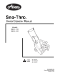
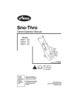
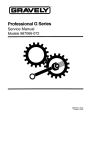
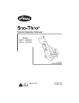
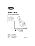
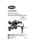
TABLE OF CONTENTS
Section 1 - Introduction . . . . . . . . . . . . . . . . .
1.1 The Manual . . . . . . . . . . . . . . . . . . . . . . .
1.2 Service and Replacement Parts . . . . . . .
1.3 Product Registration . . . . . . . . . . . . . . . .
1.4 Unauthorized Replacement Parts . . . . . .
1.5 Disclaimer . . . . . . . . . . . . . . . . . . . . . . . .
1.6 Technical Service Communications . . . . .
1-3
1-3
1-3
1-3
1-3
1-3
1-3
Section 2 - Safety . . . . . . . . . . . . . . . . . . . . . .
2.1 Safety Alerts . . . . . . . . . . . . . . . . . . . . . .
2.2 Signal Words . . . . . . . . . . . . . . . . . . . . . .
2.3 Notations . . . . . . . . . . . . . . . . . . . . . . . . .
2.4 Practices and Laws . . . . . . . . . . . . . . . . .
2.5 Required Operator Training . . . . . . . . . . .
2.6 Preparation . . . . . . . . . . . . . . . . . . . . . . .
2.7 Cleaning and Storage . . . . . . . . . . . . . . .
2.8 Safety Rules . . . . . . . . . . . . . . . . . . . . . .
2-4
2-4
2-4
2-4
2-4
2-4
2-4
2-4
2-5
Section 5 - Engine . . . . . . . . . . . . . . . . . . . . . .5-13
5.1 Engine Troubleshooting . . . . . . . . . . . . . .5-13
5.2 Storage . . . . . . . . . . . . . . . . . . . . . . . . . .5-14
5.3 Check Fasteners . . . . . . . . . . . . . . . . . . .5-14
5.4 Clean Engine Cooling System . . . . . . . . .5-14
5.5 Remove Engine . . . . . . . . . . . . . . . . . . . .5-14
Section 6 - Auger and Discharge Chute . . . .6-15
6.1 Auger . . . . . . . . . . . . . . . . . . . . . . . . . . . .6-15
6.2 Discharge Chute Deflector. . . . . . . . . . . .6-15
6.3 Unit Upgrades . . . . . . . . . . . . . . . . . . . . .6-16
Section 7 - Drive Train . . . . . . . . . . . . . . . . . .7-17
7.1 Replace Drive Belt . . . . . . . . . . . . . . . . . .7-17
7.2 Replace Wheels. . . . . . . . . . . . . . . . . . . .7-17
Section 8 - Electrical . . . . . . . . . . . . . . . . . . . .8-18
8.1 Electric Starter . . . . . . . . . . . . . . . . . . . . .8-18
8.2 Sno-thro Cable Routing . . . . . . . . . . . . . .8-18
Section 3 - Specifications . . . . . . . . . . . . . . . 3-7
Section 9 - Chute Crank Kit . . . . . . . . . . . . . .9-20
9.1 Chute Crank Kit . . . . . . . . . . . . . . . . . . . .9-20
Section 4 - General Maintenance &
Adjustments. . . . . . . . . . . . . . . . . . . . . . . . 4-9
4.1 Controls and Features . . . . . . . . . . . . . . . 4-9
4.2 Filling The Fuel Tank . . . . . . . . . . . . . . . .4-10
4.3 Service Position . . . . . . . . . . . . . . . . . . . .4-10
4.4 Adjust Discharge Chute Deflector . . . . . .4-10
4.5 Check Clutch Function. . . . . . . . . . . . . . .4-10
4.6 Adjust Auger Controls . . . . . . . . . . . . . . . 4-11
4.7 Adjust Clutch . . . . . . . . . . . . . . . . . . . . . . 4-11
4.8 Impeller Control Cable Adjustment . . . . . 4-11
4.9 Adjust Idler Position . . . . . . . . . . . . . . . . . 4-11
4.10 Adjust Belt Finger . . . . . . . . . . . . . . . . .4-12
2
SECTION 1 - INTRODUCTION
1.1 THE MANUAL
1.3 PRODUCT REGISTRATION
It is the purpose of this manual to provide complete
instructions for service, maintenance, disassembly,
repair, and installation of the mechanical components
for the 932 Sno-Thro.
A warranty registration card must be filled out, signed,
and returned at the time of purchase. This card
activates the warranty. Claims meeting requirements
during limited warranty period will be honored.
Dealer trained service personnel should use this
manual as a supplement to and reminder of the training
sessions conducted by the company.
1.4 UNAUTHORIZED REPLACEMENT
PARTS
Use only Ariens replacement parts. The replacement of
any part on this vehicle with anything other than an
Ariens authorized replacement part may adversely
affect the performance, durability, or safety of this unit
and may void the warranty. Ariens disclaims liability for
any claims or damages, whether warranty, property
damage, personal injury, or death arising out of the use
of unauthorized replacement parts.
Read all information for servicing a part of system
before repair work is started to avoid needless
disassembly.
Operation
Before operation of the unit, carefully and completely
read manuals supplied with the unit. The contents will
provide you with an understanding of safety
instructions and controls during normal operation and
maintenance.
1.5 DISCLAIMER
Directional Reference
Ariens reserves the right to discontinue, make changes
to, and add improvements upon its products at any
time without public notice or obligation. The
descriptions and specifications contained in this
manual were in effect at printing. Equipment described
within this manual may be optional. Some illustrations
may not be applicable to your unit.
All reference to left, right, front, or rear are given from
the operator in the operator position and facing the
direction of forward travel.
1.6 TECHNICAL SERVICE
COMMUNICATIONS
Safety Messages
For your safety and the safety of others always read,
understand, and follow all DANGER, WARNING, and
CAUTION messages found in manuals and on safety
decals.
1.2 SERVICE AND REPLACEMENT PARTS
When ordering publications, replacement parts, or
making service inquiries, know the Model and Serial
numbers of your unit and engine.
Numbers are located on the product registration form in
the unit literature package. They are printed on a serial
number label, located on the frame of your unit.
Serial Number
Ariens Technical Service communicates information to
the field using Service Letters, Service Bulletins,
Product Notices, and Campaigns. Each
communication signifies a type of information and
priority. The dealer is responsible to carry out the
directive provided in the communication. The types of
communication are:
Service Letter - General technical information for the
dealer. Technical information on how to service the
product and product improvements.
Service Bulletin - Notification to update products to
resolve certain issues or a notification of a policy
change.
Product Notices - Notification of limited product
located in a certain region. This is a limited distribution
to only those who received the product involved.
Campaigns - Notification of a safety related issue. All
product must be updated and are tracked by the
factory until all units are corrected.
Figure 1
1-3
SECTION 2 - SAFETY
2.1 SAFETY ALERTS
rented or sold, ALWAYS provide this manual and any
needed safety training before operation.
Look for these symbols to point out
important safety precautions. They
mean:
2.6 PREPARATION
Before starting any removal of parts, proper
preparation is very important for efficient work. A clean
work area at the start of each job will allow you to
perform service repairs easily and quickly.
Attention!
Personal Safety Is Involved!
Become Alert!
Obey The Message!
To reduce the incidence of misplaced tools or parts,
place removed components with all attaching hardware
in the disassembly order on a clean work surface.
Organization is a key part of proper reassembly.
2.2 SIGNAL WORDS
The safety alert symbol is used in decals on the unit
and with proper operation procedures in this manual.
They alert you to the existence and relative degree of
hazards.
Tools, instruments, and parts needed for the job should
be gathered before work is started. Interrupting a job to
locate tools or parts is a needless delay. A list of
required special tools has been included in this
manual.
Understand the safety message. It contains important
information about personal safety on or near the unit.
DANGER: IMMINENTLY HAZARDOUS
SITUATION! If not avoided, WILL RESULT in
death or serious injury.
CAUTION: Remove enough fuel so that no
spillage will occur. Remove battery to prevent
spillage of electrolyte.
WARNING: POTENTIALLY HAZARDOUS
SITUATION! If not avoided, COULD RESULT
in death or serious injury.
2.7 CLEANING AND STORAGE
WARNING: AVOID SHARP EDGES which
can cut. Movement of parts can cut off fingers
or a hand. Wear gloves, and use extreme
caution when servicing.
CAUTION: POTENTIALLY HAZARDOUS
SITUATION! If not avoided, MAY RESULT in
minor or moderate injury. It may also be used
to alert against unsafe practices.
2.3 NOTATIONS
NOTE: General reference information for proper operation and maintenance practices.
IMPORTANT: Specific procedures or information
required to prevent damage to unit or attachment.
2.4 PRACTICES AND LAWS
IMPORTANT: Never spray unit with water or store unit
outdoors to help prevent sealed bearing rust or
corrosion. Water can seep into sealed bearings and
reduce component life. Bearings are sealed against dirt
and debris only.
A unit that is excessively dirty should be cleaned
before work starts. Cleaning will occasionally uncover
trouble sources. Dirt and abrasive dust reduce the
efficient work life of parts and can lead to costly
replacement.
Practice usual and customary safe working
precautions, for the benefit of yourself and others.
Understand and follow all safety messages. Be alert to
unsafe conditions and the possibility of minor,
moderate, or serious injury or death. Learn applicable
rules and laws in your area.
2.5 REQUIRED OPERATOR TRAINING
Original purchaser of this unit was instructed by the
seller on safe and proper operation. If unit is to be used
by someone other than original purchaser; loaned,
2-4
NEVER fill fuel tank when engine is running, hot, or unit
is indoors.
When taking unit out of extended storage:
1. Check for any damage or loose parts. Repair,
replace, or tighten hardware before operation.
2.8 SAFETY RULES
Abnormal Vibrations are a warning of trouble. Striking a
foreign object can damage unit. Stop unit and engine.
Wait for all moving parts to stop. Remove wire from
spark plug. Inspect unit and make any necessary
repairs before restart.
Walk Around Inspection
Hazardous Slopes
Complete a walk around inspection of unit and work
area to understand:
DO NOT operate on steep slopes. Avoid operating on
slopes. When you must operate on a slope, travel up
and down the slope. Never operate cross a slope.
Never operate on a slope greater than 10 degrees.
2. If a preservative fluid was used in fuel tank, drain
and discard. Fill fuel tank with fresh new fuel.
• Work area.
• Your unit.
Child Safety
• All safety decals.
NEVER allow children to operate or play on or near
unit. Be alert and shut off unit if children enter area.
Work Area
ALWAYS check overhead and side clearances
carefully before operation. ALWAYS be aware of traffic
when operating along streets or curbs.
ALWAYS keep hands and feet within the limits of the
unit.
Keep children, people, and animals away. Keep
children out of work area and under watchful care of a
responsible adult.
Keep area of operation clear of all toys, pets, and
debris. Stay alert for hidden hazards.
DO NOT run engine in an enclosed area. Always
provide good ventilation.
Unit
ALWAYS keep protective structures, guards, and
panels in good repair, in place and securely fastened.
NEVER modify or remove safety devices.
Personal Safety
Only trained adults may operate unit.
Training includes actual operation.
NEVER operate unit after or during the use of
medication, drugs or alcohol. Safe operation requires
your complete and unimpaired attention at all times.
NEVER allow anyone to operate the unit when their
alertness or coordination is impaired.
DO NOT operate unit without wearing adequate outer
garments. Wear adequate safety gear and protective
gloves. Wear proper footwear to improve footing on
slippery surfaces.
Protect eyes, face, and head from objects that may be
thrown from unit. Wear appropriate hearing protection.
Operation
Avoid Sharp Edges. Sharp edges can cut. Moving
parts can cut or amputate fingers or a hand. Wear
gloves to service unit when handling sharp edges.
Understand:
ALWAYS keep hands away from any pinch points.
• How to operate all controls
• The functions of all controls
• How to STOP in an Emergency
DO NOT touch unit parts which might be hot from
operation. Allow parts to cool before attempting to
maintain, adjust or service.
Before starting engine, disengage auxiliary power.
NEVER place your hands or any part of your body or
clothing inside or near any moving part while unit is
running.
Always back up slowly. Always look down and behind
before and while backing.
DO NOT wear loose clothing or jewelry and tie back
hair that may get caught in rotating parts.
Never leave a running unit unattended. ALWAYS shut
off auxiliary power, lower throttle setting, and stop
engine before leaving unit. ALWAYS remove key to
prevent unauthorized use.
Keep children and people away from unit during
operating.
• Speed ranges
ALWAYS operate unit in good visibility and light.
Fuel is highly flammable and its vapors can explode.
Use ONLY approved RED fuel containers.
NO Smoking!
NO Sparks!
NO Flames!
Allow engine to cool before servicing.
Never direct discharge towards persons or property
that may be injured or damaged by thrown objects. Use
extreme caution on gravel surfaces. Stay alert for
hidden hazards or traffic.
Deflected materials can cause injury and property
damage.
Always stand clear of the discharge area when
operating this unit.
2-5
Fumes from engine exhaust can cause injury or death.
DO NOT run engine in an enclosed area. Always
provide good ventilation.
Allow hot parts to cool.
Keep unit free of dirt, stones, and other debris. Clean
up oil or fuel spills.
Service
Before cleaning, removing clogs or making any
inspections, repairs, etc.: disengage clutch(es), stop
unit and engine, remove key, allow moving parts to
stop. Allow hot parts to cool.
Before tipping unit up onto housing, remove enough
fuel so no spills will occur. Ensure unit is secure and
will not tip over during maintenance.
Fuel is highly flammable and its vapors are explosive.
Handle with care. Use an approved fuel container.
NO smoking, NO sparks, NO flames. ALWAYS allow
engine to cool before servicing.
NEVER fill fuel tank when engine is running or hot from
operation.
NEVER fill or drain fuel tank indoors.
Replace fuel cap securely and clean up spilled fuel.
ALWAYS maintain unit in safe operating condition.
Damaged or worn out muffler can cause fire or
explosion.
Keep all hardware properly tightened.
Cleaning
Keep unit free of ice or other debris. Clean up oil or fuel
spills.
Storage
For unit storage or extended storage:
• NEVER store with fuel in fuel tank, inside a building
where any ignition sources are present.
• Allow engine to cool completely.
• For extended storage, clean unit thoroughly. See
Engine Manual for proper storage.
Transport
Use extra care when loading or unloading unit onto
trailer or truck.
Secure unit chassis to transport vehicle. NEVER
secure from rods or linkages that could be damaged.
DO NOT transport machine while engine is running.
Spark Arrester
This product is equipped with an internal combustion
type engine. DO NOT use unit on or near any
unimproved, forest-covered or brush covered land
unless exhaust system is equipped with a spark
arrester meeting applicable local, state or federal
laws.A spark arrester, if it is used, must be maintained
in effective working order by operator.
2-6
SECTION 3 - SPECIFICATIONS
Model Number
Engine
Fuel to Oil Mix
Fuel Tank Capacity - qt (L)
Fast Idle RPM
938001
938002
938301
938302
HSK-600
HSK-850
HSK-850
HSK-600
938301
50:01
50:01
50:01
50:01
1.2 (1.1)
1.2 (1.1)
1.2 (1.1)
4300
3600
4300
3600
4300
N/A
2-Cycle
.030/RCJ84 Champion
7.0 x 1.5
7.0 x 1.5
7.0 x 1.5
7.0 x 1.5
7.0 x 1.5
(18 x 3.8)
(18 x 3.8)
(18 x 3.8)
(18 x 3.8)
(18 x 3.8)
1200
1200
Installed
73700100
Discharge Distance - ft (m)
3-30 (0.9-9.1)
Chute Turning Radius
220o
Auger Size (dia) - in (cm)
9.0 (23)
1220
1200
Auger Clutched
1220
Belt Idler Clutched
Blower Housing Height - in (cm)
13.25 (33.66)
Blower Housing Width - in (cm)
Model Number
HSK-600
1.2 (1.1)
Spark Plug Gap-in (cm)/Type
Electric Starter Kit
938006
50:01
Engine Oil Type
Auger RPM
938004
1.2 (1.1)
Crank Case Capacity - oz (L)
Tire Size- in (cm)
938003
22 (56)
73700100
Installed
Installed
938007
938008
938009
938303
Engine
Fuel to Oil Mix
Fuel Tank Capacity - qt (L)
Fast Idle RPM
HSK-600
HSK-850
HSK-600
HSK-850
50:01
50:01
50:01
50:01
50:01
1.2 (1.1)
1.2 (1.1)
1.2 (1.1)
1.2 (1.1)
1.2 (1.1)
3600
4300
3600
4300
3600
7.0 x 1.5
7.0 x 1.5
7.0 x 1.5
(18 x 3.8)
(18 x 3.8)
(18 x 3.8)
1220
1200
73700100
Installed
N/A
Engine Oil Type
2-Cycle
Spark Plug Gap-in (cm)/Type
.030/RCJ84 Champion
7.0 x 1.5
7.0 x 1.5
(18 x 3.8)
(18 x 3.8)
Discharge Distance - ft (m)
3-30 (0.9-9.1)
Chute Turning Radius
220o
Auger Size - in (cm)
Auger RPM
Auger Clutched
9.0 (23)
1200
1220
1200
Belt Idler Clutch
Blower Housing Height - in (cm)
13.25 (33.66)
Blower Housing Width - in (cm)
Electric Starter Kit
938011
938305
HSK-850
Crank Case Capacity - oz (L)
Tire Size- in (cm)
938010
938004
22 (56)
Installed
Installed
3-7
Installed
Model Number
938012
938015
938016
HSK-850
HSK-600
HSK-850
938305
Engine
Fuel to Oil Mix
Fuel Tank Capacity - qt (L)
Fast Idle RPM
50:01
50:01
50:01
1.2 (1.1)
1.2 (1.1)
1.2 (1.1)
3600
4300
3600
Crank Case Capacity - oz (L)
N/A
Engine Oil Type
2-Cycle
Spark Plug Gap-in (cm)/Type
Tire Size- in (cm)
.030/RCJ84 Champion
7.0 x 1.5
7.0 x 1.5
7.0 x 1.5
(18 x 3.8)
(18 x 3.8)
(18 x 3.8)
Discharge Distance - ft (m)
3-30 (0.9-9.1)
Chute Turning Radius
220o
Auger Size - in (cm)
Auger RPM
9.0 (23)
1200
Auger Clutched
Blower Housing Height - in (cm)
1200
13.25 (33.66)
Blower Housing Width - in (cm)
Electric Starter Kit
1220
Belt Idler Clutched
22 (56)
Installed
73700100
3-8
Installed
SECTION 4 - GENERAL MAINTENANCE & ADJUSTMENTS
4.1 CONTROLS AND FEATURES
18
19
22
1
15
16
2
23
3
14
21
20
4
5
OS0241
17
6
7
12
11
8
13
9
10
1. Auger Clutch Bail
2. Recoil Starter Handle
3. Handlebar Knob
4. Chute Deflector Handle
5. Exhaust
6. Discharge Chute Deflector
7. Discharge Chute
8. Auger Housing
9. Auger
10.Scraper Blade
11.Discharge Chute Rotation Handle
12.Fuel Tank and Cap
13.Cowl
14.Auger Control Cable
15.Upper Handlebar
16.Lower Handlebar
17.J - Bolt
18.Primer Bulb
19.Ignition Switch
20.Fuel Level Indicator
21.Starter Button (optional)
22.Power Cord (optional)
23.Choke Control Knob
OS1500
Figure 2
4-9
4.2 FILLING THE FUEL TANK
4.3 SERVICE POSITION
Check fuel level by looking at fuel level indicator on
rear of unit. Add fuel as required.
Place unit on a flat level surface.
4.4 ADJUST DISCHARGE CHUTE
DEFLECTOR
WARNING: FLAMMABLE FUEL and its
EXPLOSIVE VAPORS can result in death or
serious injury.
DANGER: ROTATING PARTS will cause
serious injury or death. NEVER reach into
discharge chute or housing while engine is
running.
Handle fuel with extreme care.
ALWAYS use an approved fuel container.
No Smoking! No Lighted Materials! No Open
Flames!
Allow engine to cool before any service.
ALWAYS clean up any spilled fuel.
Add fuel to fuel tank:
IMPORTANT: Two cycle engines require that oil be
mixed with fuel. Failure to mix oil with fuel will result in
seizure and severe damage to engine. DO NOT use
gasohol or gasoline containing alcohol because alcohol
will cause internal parts to deteriorate. See Engine
Manual for correct type and grade of fuel.
If discharge chute deflector does not stay in set
position during operation, adjust chute by tightening
fasteners evenly until deflector stays in position.
NOTE: Use a T30 torx drive or a 3/16" (.19 cm) wide
straight screwdriver to tighten.
1. ALWAYS place unit in open or well ventilated area.
2. Stop engine and allow to cool.
Fasteners
3. See engine manual for proper fuel/oil mixture.
4. Clean fuel cap and surrounding area to prevent dirt
from entering fuel tank.
5. Remove cap.
6. Fill fuel tank with mixture. Tank capacity is 1.2
quarts (1.1 liters).
NOTE: Fuel mixture left standing for prolonged periods
will begin to separate; thoroughly shake mixture before
use.
Figure 3
4.5 CHECK CLUTCH FUNCTION
WARNING: FAILURE OF CLUTCHES OR
BRAKES may result in death or serious injury.
Check clutch and brake function before each
use. Repair or adjust before operation.
7. Replace fuel cap and tighten.
WARNING: ACCIDENTAL ENGINE START
UP can cause death or serious injury.
ALWAYS stop engine, remove key, and wait
for moving parts to stop before performing
maintenance or service.
HOT SURFACES can cause death or serious
injury. DO NOT touch parts which are hot from
operation. ALWAYS allow parts to cool.
CAUTION: FUEL SPILLS may result in minor
or moderate injury and/or damage to unit. If
unit must be tipped, remove enough fuel so
that no spills will occur.
OS0181
With key in "STOP" position, squeeze auger clutch bail
to Engaged position and pull recoil starter handle.
Auger should rotate with the turning of the engine.
Release the auger clutch bail.
If the auger clutch bail moves freely with no resistance
before contacting handlebar, adjust or repair.
NOTE: The unit will require control cable and/or idler
adjustment after 20 hours of operation on a new unit or
new drive belt. See Service and Adjustments for
instructions.
4 - 10
WARNING: IMPROPER ADJUSTMENT
could result in death or serious injury. AUGER
BRAKE MUST DISENGAGE when clutch is
engaged. BRAKE MUST STOP AUGER
WITHIN 5 SECONDS of releasing auger
clutch bail.
4.6 ADJUST AUGER CONTROLS
WARNING: IMPROPER ADJUSTMENT
could result in death or serious injury. AUGER
BRAKE MUST DISENGAGE when clutch is
engaged. BRAKE MUST STOP AUGER
WITHIN 5 SECONDS of releasing auger
clutch bail.
Locknut
Figure 4
OS0011
4.7 ADJUST CLUTCH
For brake to function properly, there must ALWAYS be
some slight, noticeable slack in the control cable inner
wire when the impeller clutch bail is disengaged
(lowered position). This allows extension spring to pull
idler arm/brake, braking belt. Bail should travel 6-3/4 to
7-1/4" (17.1-18.4 cm) before contacting handlebars on
models 938006-938012, 938301, 938303. If brake
does not stop impeller within 5 seconds of releasing
impeller clutch bail, inner wire slack must be adjusted.
1/4 - 3/8"
1
2
Models 938001-938009, 938301-931303
There should be 1/8" to 3/16" extension of cable spring
when clutch bail is held against handlebar.
4
5
Models 938010-938012
3
A properly adjusted clutch must extend control cable
Spring approximately 1/4 to 3/8" before clutch bail
contacts handlebar.
1.
2.
3.
4.
A properly adjusted clutch must show a noticeable
increase in resistance (caused by stretch of control
cable spring) before impeller clutch bail contacts
handlebar. As drive belt seats and wears, increase in
resistance will occur closer to handlebar contact. If no
resistance occurs, inner wire slack must be adjusted.
Control Cable Spring
Adjusting Feature
Locknut
Threaded Section
5. Solid Section
Figure 5
OS1220
4.9 ADJUST IDLER POSITION
4.8 IMPELLER CONTROL CABLE
ADJUSTMENT
The idler must be as close as possible to the drive belt
when the auger clutch is disengaged, but not so close
that it causes auger rotation.
1. Shut off engine, allow to cool and remove cowl.
2. Loosen locknut on threaded section of control
cable adjusting feature (Figures 4 and 5.)
3. Turn solid section to remove almost all slack in
cable.
4. Hold the solid section with a pliers and gently, with
a small wrench, tighten the locknut.
IMPORTANT: If there is still no resistance, the idler
position must be adjusted.
See Figure 6.
4 - 11
WARNING: ROTATING PARTS can cut off
body parts. Keep hands and feet away. Loose
clothing, long hair or scarves can get caught
in rotating parts and cause death or serious
injury.
4.10 ADJUST BELT FINGER
To adjust the idler position:
IMPORTANT: If adjustment cannot be achieved, the
drive belt must be replaced.
3HP units have two belt fingers.
5HP units have one belt finger.
1. Shut off engine, allow to cool, and remove cowl.
With the auger clutch engaged, there should be 1/32 to
1/16" (1-1.6 cm) clearance between the belt finger and
drive belt.
2. Ensure control cable has some slight, noticeable
slack when auger clutch is disengaged (bail in
lowered position).
To adjust:
3. Ensure belt fingers are properly adjusted. See To
Adjust Belt Finger.
1. Loosen bolt holding the belt finger.
4. Loosen idler hardware, reposition idler along slot in
idler arm, and tighten hardware.
5. Check for proper extension of control cable spring.
See To Adjust Auger Control Cable.
2. Rotate the belt finger around the bolt to the correct
position.
3. Tighten bolt.
6. Start engine and ensure auger does not rotate
when auger clutch is disengaged.
7. Shut off engine.
8. Repeat the above steps until proper adjustment is
achieved.
9. Replace cowl.
NOTE: Due to the need for maximum amount of belt
tension to operate the single stage sno-thro and the
slippage that is encountered with the original belt after
the break in period, a new shorter replacement belt has
been put into the parts system. This belt has the original belt number but has the letter "A" after the part
number. The new belt will allow a longer run time
between adjustment intervals. Bail travel should be
4 1/2" to provide proper belt tension. If the 4 1/2" travel
cannot be obtained the original bail may be replaced
with a bail part #03806351.
1
2
1/32" - 1/16"
(1 - 1.6 cm)
3
4
5
5 (3 HP)
1. Idler Arm/Brake
2. Idler
3. Slot
4. Auger Clutch Control
Cable
5. Belt Fingers
Figure 6
OS0053
4 - 12
SECTION 5 - ENGINE
5.1 ENGINE TROUBLESHOOTING
The following troubleshooting chart is to be used to
isolate engine problems and give possible causes and
corrective action responses.
The troubleshooting key is generic for 2 cycle engines
and can be used for several types of engines. Use only
those possible causes and corrective actions that apply
to the unit.
TROUBLE
Black Exhaust
Blue/White Exhaust
Difficult Starting
Erratic Running
Excessive Fuel Consumption
Knocking
Loss of Power or System
Low Cranking Power
Misfiring
Overheating
Poor Compression
Starts and Stops
POSSIBLE CAUSES (Refer to Key Below)
20, 22, 25, 29, 31, 32, 33
4, 20, 25, 31, 33, 34
5, 8, 10, 20, 21, 22, 29, 31, 32, 33
8, 9, 10, 20, 21, 26, 29, 33, 59, 62
20, 22, 25, 31, 32, 33
22, 26, 29, 31, 33, 36, 46, 59
8, 10, 20, 21, 22, 25, 26, 31, 32, 33
2, 3
10, 20, 25, 26, 28, 29, 32
19, 25, 63
25, 28, 29, 31, 32, 33, 34, 59
6, 10, 62
Vibration
Will Not Crank
Will Not Start
20, 25, 26, 29, 33, 48, 49
2, 3
6, 8, 10, 21, 22, 62
CORRECTIVE ACTION
repair or replace
repair or replace
repair or replace
repair or replace
repair or replace
repair or replace
repair or replace
repair or replace
repair or replace
repair or replace
repair or replace
repair or replace
see electrical systems
see engine service manual
repair or replace
charge battery or replace
repair or replace
see electrical systems
see engine service manual
TROUBLESHOOTING KEY
1
2
3
4
Restriction in air cleaner
Bad electrical connection
Faulty starter motor
Incorrect grade of lubricating
oil
Low cranking speed
Fuel tank empty
Controls not in correct
operation position
Blocked fuel feed line
Faulty fuel lift pump
Choked fuel filter
Battery capacity low
Air in fuel system
22
23
24
25
Incorrect grade of fuel
Sticking throttle/restricted movement
Exhaust pipe restriction
Leaking cylinder head gasket
43
44
45
46
Faulty suction pipe
Choked oil filter
Bad solenoid switch
Incorrect piston height
26
27
28
Overheating
Cold running
Incorrect tappet adjustment
47
48
49
29
30
31
32
33
50
51
52
53
54
34
35
36
Worn or damaged bearings
57
Choked breather pipe
Damaged valve stem oil deflector (if
fitted)
Coolant level too low
37
38
Insufficient oil in sump
Bad/defective oil temperature switch
58
59
Blocked sump strainer
Broken valve spring
18
19
Faulty fuel injection pump
Faulty fuel injectors or
incorrect type
Incorrect use of cold start
equipment
Faulty cold start equipment
Broken fuel injection pump
drive
Incorrect fuel pump timing
Incorrect valve timing
Sticking valves
Incorrect high pressure pipes
Worn cylinder bores
Pitted valves and seats
Broken, worn or sticking piston
ring(s)
Worn valve stems and guides
Restriction in air cleaner
Damaged fan
Faulty engine mounting
Incorrectly aligned flywheel and/or
flywheel housing
Faulty thermostat
Restriction in water jacket
Loose fan belt
Choked radiator
Faulty water pump
39
40
Oil pump worn
Pressure relief valve sticking open
60
61
20
21
Poor compression
Blocked fuel tank vent
41
42
Pressure relief valve sticking closed
Broken relief valve spring
62
63
Exhaust or vacuum pipe leak
Bad or defective water temperature
switch
Bad spark plug(s)
Improper amount of oil in fuel mixture
5
6
7
8
9
10
11
12
13
14
15
16
17
5 - 13
55
56
5.2 STORAGE
5.5 REMOVE ENGINE
When storing unit for extended periods of time, remove
all fuel from tank and carburetor (run dry). Refer to
Engine Manual.
5.3 CHECK FASTENERS
1. Remove gas cap and top cowling.
2. Remove fuel line at the engine and drain fuel into a
suitable container. Save for reuse or dispose of
properly.
3. Remove drive belt from engine pulley.
Keep all nuts, bolts, and screws properly tightened.
4. Remove bolt and washer from engine shaft and
slide drive pulley halves from shaft.
5.4 CLEAN ENGINE COOLING SYSTEM
5. Disconnect throttle cable from engine.
Engine is air cooled. Air must circulate freely around
engine to prevent overheating.
Every year (more often if conditions require) remove
cooling shrouds and clean cooling fins. Clean external
surfaces of engine of dust, dirt and oil deposits which
can contribute to improper cooling. Refer to Engine
Manual.
IMPORTANT: DO NOT operate engine with cooling
shrouds removed. Engine overheating and damage will
result.
6. On models with recoil starters, unbolt the bracket
that holds the recoil handle to the lower handle bar.
7. Remove wiring for key switch.
8. Unscrew bolts from shaft side of engine.
9. Unscrew mounting nuts on recoil side.
10.Disconnect choke cable.
11.Remove engine.
Install in reverse order.
The engine on the Sno-Thro is a 2-cycle design. The
lubricating oil is mixed with the gasoline. Consult the
engine manufacturers manual for the proper grade and
mix ratio.
1
2
3
1. Hex Bolt
2. Drive Pulleys
3. Engine Mounting
Bracket
Figure 7
5 - 14
PS0034
SECTION 6 - AUGER AND DISCHARGE CHUTE
6.1 AUGER
6.2 DISCHARGE CHUTE DEFLECTOR
The auger consists of two halves bolted together over
the auger shaft.
(938001, 938003, 938006-938009, 938301,
938303)
To replace the auger:
If chute deflector does not stay in set position, tighten
fasteners evenly until deflector stays in position
(Figure 8). Use a #T30 Torx drive or a 3/16" (.19 cm)
wide straight screwdriver to tighten.
1. Unscrew the twelve self tapping screws.
2. Remove one half.
3. Rotate second half out.
NOTE: The screws tap into a metal plate. Save these
for reassembly.
938002, 938004, 938302
Adjust chute deflector control lever pivot bolt nut until
the control stays in position. (Figure 9).
Check roll pins in auger shaft and replace as needed.
When the chute deflector hits its stop for maximum
down deflection, the chute deflector control lever
should hit its stop on housing at the same time.
Assemble in reverse order.
Lock in position by adjusting and tightening nuts
against bracket. (Figure 9)
Discharge chute may freeze in extreme cold conditions
and not rotate freely. To correct for this condition the
discharge chute handle assembly will need to be
removed from the gear discharge chute segment. The
pocket in the handle assembly for the spring and ball
detent will need to be packed with grease. The metal
ring in which the discharge chute is trapped will need a
liberal coat of grease as well.
1
3
2
3
4
1. Discharge Chute
Rotation Bracket
2. Self-Tapping Bolt Plate
3. Half Auger
4. Auger Shaft
Figure 8
PS0063
6 - 15
Figure 9
6.3 UNIT UPGRADES
Discharge Deflector Control Force (5HP)
938002, 938004, 938302
The discharge deflector control force is dependent on
the bolt through the compression spring in the deflector
handle assembly and by the construction of the
housing assembly. To correct breakage of the housing
alignment pins that go into the handlebar tube, remove
them and replace with a flat head screw. The flat head
screw will hold the deflector housing securely to the
handlebar. The compression spring will then only be
required to control the chute deflector lever force.
Blower Housing Filling With Snow
Snow may enter the engine compartment and get
trapped inside with no exiting points. To control the
amount of snow that would be trapped inside the
engine compartment, two 3" holes will need to be
added to the chassis bottom and allow the snow to exit.
To control the snow from entering the drive belt area,
use 538012 3 HP Update Kit (938001 - S/N 000101 006245, 938003 - S/N 000101 - 002350, 938301 - S/N
000101 -000251) 53801300 5HP Update Kit (938002 S/N 000101 -00 6280, 938004 - S/N 000101 - 003900,
938302 - S/N 000101 - 000241). New holes will need to
be drilled for the two additional screws, in the front of
the blower housing where the right and left bearing
support plates come into contact with the impeller
housing.
6 - 16
SECTION 7 - DRIVE TRAIN
7.1 REPLACE DRIVE BELT
7.2 REPLACE WHEELS
1. Remove fuel cap.
1. Support unit with wheels off the ground.
2. Remove cowl and replace fuel cap.
2. Remove hub cap.
3. Disconnect extension spring on idler arm/brake.
3. Pry E-ring clip from shaft.
4. Remove cap screw and washer from end of auger
shaft and pull off auger drive pulley.
4. Remove wheel.
Assemble in reverse order.
5. Remove old belt.
6. Install new belt onto pulleys.
7. Reinstall auger drive pulley and secure with
washer and cap screw.
2
8. Reconnect extension spring to idler arm/brake.
9. Ensure belt finger(s) and auger clutch control cable
are properly adjusted. See To Adjust Belt Finger
and To Adjust Auger Control Cable in General
Maintenance & Adjustments.
1
10.Remove fuel cap and replace cowl.
11.Replace fuel cap.
1
1. Hub Cap
2. External Retaining
Ring
1/32"-1/16" (1-1.6 cm)
3
2
4
6
5
7
5
9
1.
2.
3.
4.
5.
8
Extension Spring
Idler/Arm/Brake
Idler
Slot
Belt Fingers
6. Auger Clutch Control
Cable
7. Drive Belt
8. Auger Drive Pulley
9. Cap Screw, Washer,
Auger Shaft
Figure 10
OS0053
7 - 17
Figure 11
SECTION 8 - ELECTRICAL
8.1 ELECTRIC STARTER
tank neck. Measure 10" of fuel line from carburetor and
trim off excess (reference A), see Figure 12.
Electric starter is not equipped with a thermal cutout
switch. DO NOT crank engine for more than a total of
20 seconds without allowing electric starter to cool
down for 10 minutes. Failure to do this can severely
damage electric starter.
Turn eyelet on top of engine containing the green
ground wire to the two o’clock position (reference B)
and wrap a 2" piece of electrical tape 2" up from the
eyelet, taping the two wires together (reference C). On
electric start unit the green wires should be routed over
the electric start cable.
8.2 SNO-THRO CABLE ROUTING
IMPORTANT: This procedure should be done on all
units to prevent wiring from getting caught in the chute
crank gears.
Place the Sno-Thro on a raised work surface. Remove
ignition key, and drain all fuel from the fuel tank.
Remove the gas cap and remove the engine cowl part
#38005. Retain all hardware for reassembly later.
Remove the cable tie from the two green ignition wires
and from fuel tank support bracket. Remove the fuel
tank from the unit and retain the cable tie around the
ref. H
chute cable
Measure and drill a 1/8" hole in the upper right corner
of the engine blower housing 5/8" from each edge
(reference D) Figure 13. Cover carburetor before
drilling to keep particles out of carburetor throat.
Measure and drill a 3/8" hole for the primer hose 2"
down and 5/8" out of the corner (reference E). Remove
primer hose from carburetor and reroute through the
new hole and reattach to the carburetor (reference F),
see Figure 12.
ref. I
cable tie
ref. M
cable tie
ref.A
gas line hose
ref. E
drill 3/8" hole
ref. C
electric tape
ref. B
eyelet
ref. F
primer hose
Upper photo of cable routing and anchor point.
Figure 12
8 - 18
Install cable clamp onto remote deflector cable 25"
from handlebar and at the start of the black protective
covering (reference G), see Figure 13. The hole for the
clip should be in the down position. Attach the clip to
the engine blower housing with the self-tapping screw.
Excess cable should be pulled up and out of blower
behind discharge chute (reference H).
Reinstall fuel tank into Sno-Thro with hardware
removed earlier, place cable tie around fuel tank neck
with green ignition wires. Check location of green
ignition wires to chute crank gear for proper clearance
(reference 1) see Figure 12.
On 938004, the electric start cable will need to be held
in place with a cable tie to clear chute crank gear. Drill
a 1/4" hole by measuring 1/4" down and out 1/4" from
recess in center of Sno-Thro frame (reference J), see
Figure 14.
Attach cable ties in the proper locations shown in the
photos as references K, L, and M. Recheck cable and
wiring routings before reinstalling engine cover. Return
machine to stock or customer.
ref. L
cable tie
ref. G
install cable clamp
ref. D
drill 1/8" hole
Right side photo of cable routing and anchor point.
Figure 13
ref. K
cable tie
ref. J
drill 1/4" hole
Rear photo of cable routing and anchor points.
Figure 14
8 - 19
SECTION 9 - CHUTE CRANK KIT
9.1 CHUTE CRANK KIT
Instructions
1. Remove cowl from unit by loosening 8 screws at
lower front sides. Remove two screws at rear
corners and remove fuel cap. After removing cowl,
replace fuel cap to avoid spills and fumes.
(for use on models 938010, 015, 016, 305)
WARNING: FAILURE TO FOLLOW
INSTRUCTIONS could result in personal
injury and/or damage to unit.
2. Install flange bushing in discharge chute rotation
bracket with flange toward centerline of chute.
Then hold the 18 tooth chute pinion in place in front
of the bushing by rolling it in place in mesh with the
chute gear. The identification marks on pinion and
gear must line up with each other, see Figure 15.
Read, understand, and follow all safety
practices in Owner/Operator Manual before
beginning.
View alignment marks through this slot.
7
6
8
1
2
3
1.
2.
3.
4.
4
5
1
Pinion-Discharge Chute 18 T
Flange Bushing
Crank Pinion 12 T
Chute Crank Shaft
5.
6.
7.
8.
Internal Hair Pin
Chute Assembly Crank
Knob
Crank Gear 48 T
Figure 15
space and tooth identification marks. Align if
necessary. Insert cotter pin (taped to chute crank
assembly) through 48T gear and chute crank shaft.
Minor movement of the crank Shaft or discharge
chute handle may be needed to align holes. Rotate
chute crank to access cotter pin and secure pin by
bending ends over. Reinstall nut, securing chute
crank and starter handle brackets to lower handle
bar.
3. Install the 12 tooth pinion on the transfer shaft so
that the drive tang/stops are seated in the notches
in the pinion. Insert the shaft through the hole in
the chassis, through the flange bushing and finally
through the 18 tooth chute pinion. Align the hole in
the shaft with the holes in the pinion. Install the
small hair pin through the holes so that it seals
over the hub of the pinion.
4. Remove nut from bolt that holds recoil starter
Handle bracket in place. Install the chute crank
assembly beneath the lower handlebar by starting
end through hole in chassis. Hold crank spacer
and then 48 tooth gear in place, sliding only as far
as needed to get them started. With crank knob
straight up and discharge chute straight forward,
check that 48T gear meshed with 12T pinion at
OS1650
5. You will note that too much effort is required to
rotate the chute. To reduce that effort, remove the
three bolts that hold the discharge chute onto the
ring and remove the chute. Then remove the four
screws that attach the ring to the chute gear, and
remove the ring. Now you can remove the detent
ball and spring and replace the above parts in
9 - 20
neck of the fuel tank with the large tie-wrap. The
wires and primer hose must be held together with
the small tie-wrap. Turn the crank stop-to-stop
several times to ensure there is no rubbing or
pinching possible.
reverse order. Check to ensure that the gear and
pinion marks have not lost their alignment from
step 2.
6. Great care must be taken to ensure that the
ignition switch wires, primer hose, and electric
starter cable (if applicable) do not rub on or
become entangled in the chute crank gears. The
electric start cable must be secured with the
medium tie-wrap to the corner of the chassis. The
ignition switch wires must be tie-wrapped to the
7. Remove the fuel cap, install the cowl and fasten in
place with all 10 screws.
8. Replace fuel cap.
Space and Tooth
Identification Marks
6
4
3
5
1
1. Crank Spacer
2. Crank Gear 48 T
3. Lower Handlebar
2
4. Recoil Starter Handle Bracket
5. Chute Crank Bracket
6. Chute Crank Assembly
Figure 16
9 - 21
IS0211
Ariens Company
655 West Ryan Street
P.O. Box 157
Brillion, WI 54110-0157
920-756-2141
Fax 920-756-2407
www.ariens.com