1
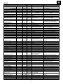
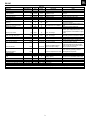
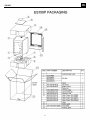
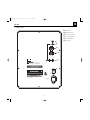
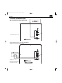
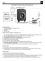
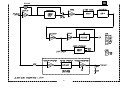
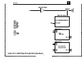
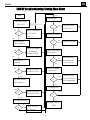
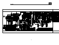
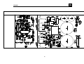
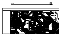
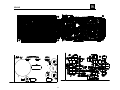
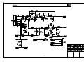
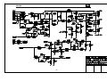
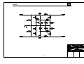
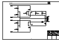
ES Series
ES150P
Powered Subwoofer
Service Manual
JBL Consumer Products
250 Crossways Park Dr.
Woodbury, New York 11797
Released 2008
Discontinued XXXX
Rev0
3/2008
ES150P
- CONTENTS BASIC SPECIFICATIONS …………….……..…………..1
DETAILED SPECIFICATIONS ……….……..…………..2
PACKING……..……………………………….….….….....4
CONTROLS/CONNECTIONS………………..…...…..…5
OPERATION ……..………………….……...…….….…...7
EXPLODED VIEW/PARTS LIST…….….….…………....8
TEST SET-UP AND PROCEDURE….….……………....9
AMPLIFIER BLOCK DIAGRAM…….………….……..…10
DETAILED TROUBLESHOOTING..……………… ……12
P.C.B. DRAWINGS….…………………………………….13
ELECTRICAL PARTS LIST ..……….……….……….…18
IC/TRANSISTOR PINOUTS..……..….…….….….….….23
SCHEMATICS…………………………………………….24
ES150P SPECIFICATIONS
Amplifier Power (RMS):
300 Watts
Peak Dynamic Power *:
500 Watts
Driver:
10" (254mm) PolyPlas™
Inputs:
Line Level (switchable to LFE)
Low-Pass Frequency:
Variable from 50Hz to 150Hz
(24dB/octave, continuously variable)
Frequency Response:
27Hz – Low-pass crossover setting
Dimensions (H x W x D):
18" x 13-1/4" x 15-1/4" (457mm x 337mm x 387mm)
Weight:
39 lb/17.7kg
JBL continually strives to update and improve existing products, as well as create new ones. The
specifications and details in this and related JBL publications are therefore subject to change without notice.
* The Peak Dynamic Power is measured by recording the highest center-to-peak voltage measured across the output of a resistive load equal to
minimum impedance of the transducer, using a 50Hz sine wave burst, 3 cycles on, 17 cycles off.
1
ES150P
JBL ES150P 225W Powered Sub Amp
LINE VOLTAGE
US 120vac/60Hz
EU 230vac/50-60Hz
Parameter
Amp Section
Type (Class AB, D, other)
Min. Load Impedance (speaker)
Yes/No
Yes
Yes
Hi/Lo Line
108-132
207-253
Nom.
120
230
Specification
Unit
QA Test
Limits
D
4
n/a
Ohms
n/a
n/a
5.18
225
Ohms
Watts
AVG System impedance
Rated Output Power
Unit
Vrms
Vrms
Conditions
Nominal
AP Computed based on system
Reference impedance curve
210
245
0.5
0.2
10
Watts
%
%
mV-DC
240
1
0.3
30
22k filter
22k filter
@ Speaker Outputs
Damping factor
>50
DF
20
Measured at amplifier board
Input Sensitivity
Input Frequency
L or R Inputs
LFE mode using L or R inputs
System Gain
50
11
11
45
Hz
mVrms
mVrms
dB
Signal to Noise
SNR-A-Weighted
SNR-unweighted
80
65
dBA
dBr
50
Nominal Freq.
±1dB
To 1 Watt
±1dB
To 1 Watt
Reference
Residual Noise Floor
<2.0 mVrms(max)
2.5
relative to 1W
relative to 1W
Volume @max, w/ A/P Swept
Bandpass Measurement (Line
freq.+ harmonics) (BW=20 KHz)
Input Impedance
Line Input (L, R,LFE)
10K
ohms
n/a
Nominal
Hz
± 10
Filters
LP filter Variable
Subsonic filter (HPF) 2nd Order
Friend circuit
LFE Low pass
50-150
Fixed
Fixed
200>LP<500
Notes
Over the BW of 20 to 500Hz
Average RMS power, 3/20 Cycles 50 Hz,
Driven 6dB above its input sensitivity ,
average of the first 4 consecutive peaks
AVG RMS Dynamic Power
THD @ Rated Power
THD @ 1 Watt
DC Offset
75
60
Notes
Normal Operation
Normal operation, MOMS required
Measured at the speaker cable. 189 Watts
@ THD < 0.1 % @ 50 Hz
Single input driven
Single input driven, LFE switch ON
Single input driven Normal or LFE mode
A-Weighting filter
22K filter
Line level inputs must be terminated using
1KOHM
4th Order variable-24 db/Octave
LFE input driven only
Hz
Limiter
13
THD at Max. Output Power
Features
Volume pot Taper (lin/log)
Phase switch
LP Filter defeat switch
LED indicator
%
Drive unit 6dB above the required
level to obtain full power
Maximum THD as a result of limiting.
functional Approximately 208mV
-LOG
0-180
YES
-deg
YES
functional
functional
functional
A Taper
functional
Disables LP filter, intended for LFE
Bicolor LED located in top of the cabinet,
RED-Standby, GRN-Active
Input Configuration
Line In (L,R) & LFE
YES
--
functional
Dual RCA jack, for LFE use either L or R inputs
Signal Sensing (ATO)
Auto-Turn-On (yes/no)
ATO Input test frequency
ATO Level LFE Input
YES
50
2
Hz
mV
functional
functional
functional
Maximum acceptable level.
Amp connected and AC on, then
functional input signal applied
T before muting, after signal is
5-15
removed
Auto turn of time (T) must be 5 > T < 15
Minutes
ATO Turn-on time
Auto Mute/ Turn-OFF Time
Power on Delay time
5
5-15
3
ms
minutes
sec.
4
After AC Power is applied
2
ES150P
Unit
QA Test
Limits
0.5
0.5
0.5
V-peak
V-peak
V-peak
0.5V
0.8V
0.8V
Efficiency
61
%
60
Efficiency at 1/8 of rated power
Off state input power
45
12
%
Watts
42
14
Test conducted at 31.25 WRMS
Stand-by Input Power
18
Watts
18
@ nom. line voltage
Nominal Line voltage
Nominal Line voltage-Rated impedance 4
Ohms
Nominal Line voltage RED LED
Maximum allowable input power under
nominal Input voltage and frequency, HOT
or COLD operation. LED GREEN no signal
applied
367
Watts
375
@ nom. line voltage
225 Watts @ 4 Ohms nominal line voltage
Parameter
Specification
Conditions
Notes
Transients/Pops
ATO Transient
Turn-on Transient
Turn-off Transient
@ Speaker Output
@ Speaker Output
@ Speaker Output
Amplifier activated by signal presence at the
Line input
AC Line cycled from OFF to ON
AC Line cycled from ON to OFF
Efficiency
Power Cons. @ rated power
Test conducted at rated power
250W
Protections
Short Circuit Protection
YES
Thermal Protection
YES
DC Offset Protection
Line Fuse Rating
USA-Domestic
YES
EU
Amplifier should resume operation after
short circuit condition removal
Temperature rise in accessible metal parts
should not exceed 35K rise for domestic
@1/8 max unclipped Power at
version or 30K rise for European versions
functional 1.06 times the input voltage
(refer to requirements sheet).
Design must insure no Offset at the speaker
output under any operating condition
DC present at Speaker Out leads including abnormal operation
functional Direct short at output
3.15
Amps
3.15
2
Amps
2
Type-T or Slo Blo-250 V
Type-T or Slo Blo-250 V, Low
Breaking capacity
Internal fuse with UL/SEMKO rated holder
Internal fuse with UL/SEMKO rated holder
Other Parameters/Notes:
1. Limiter circuit response must be clean sounding with no apparent pops, noises, or pumping.
2. Plate dimensions not to exceed 11.81"H x 7.87"W and the plate must be airtight with no possibility of air leaks (plastic cover required).
3. Volume control should be at the input buffer stage in order to lessen the possibility of clipping the input section with highly dynamic audio material.
4. ALL SPECS SHOULD BE MEASURED AT NOMINAL LINE VOLTAGE.
3
ES150P
4
ES150/250P (12V) OM
6/21/07
3:03 PM
Page 6
ES150P
CONTROLS AND CONNECTIONS
Rear Panel
¡ Phase Switch
™ LFE/Normal Selector
£ Subwoofer-Level Control
¢ Crossover Adjustment
∞ Line-Level/LFE Input
§ Power Switch
¡
™
£
¢
∞
§
AC 120V~60Hz
2A
4
5
ES150/250P (12V) OM
6/21/07
3:03 PM
Page 7
ES150P
SYSTEM CONNECTIONS
If you have a Dolby® Digital or DTS® receiver/processor
with a low-frequency-effects (LFE) or subwoofer output:
Set LFE/Normal switch to “LFE.”
If your receiver/processor does not contain a Dolby Digital
or DTS processor, but has subwoofer outputs:
Set line-level/LFE switch to
“Normal.”
NOTE: If your receiver/processor
has only one sub out, you may
use either the L or R input.
6
5
ES150/250P (12V) OM
6/21/07
3:03 PM
Page 8
ES150P
OPERATION
MAINTENANCE AND SERVICE
Power On
Plug your subwoofer’s AC cord into a wall outlet. Do not use the outlets on the
back of the receiver.
Initially set the Subwoofer-Level Control £ to the “min” position.
The enclosure may be cleaned using a soft cloth to remove fingerprints or to
wipe off dust.
Turn on your sub by pressing the Power Switch § on the rear panel.
All wiring connections should be inspected and cleaned or remade periodically.
The frequency of maintenance depends on the metals involved in the connections,
atmospheric conditions and other factors, but once per year is the minimum.
The grille may be gently vacuumed. Stains may be removed with an aerosol
cleaner, following its instructions. Do not use any solvents on the grille.
Turn on your entire audio system and start a CD or movie soundtrack at
a moderate level.
If a problem occurs, make sure that all connections are properly made and
clean. If a problem exists in one loudspeaker, reverse the connection wires to
the left and right system. If the problem remains in the same speaker, then the
fault is with the loudspeaker. If the problem appears in the opposite speaker,
the cause is in another component or cable. In the event that your subwoofer
ever needs service, contact your local JBL dealer, or visit www.jbl.com for
a service center near you.
Auto On/Standby
With the Power Switch § in the ON position, the Status LED on the
top will remain lit in red or green to indicate the On/Standby mode
of the subwoofer.
RED = STANDBY (No signal detected, Amp Off)
GREEN = ON (Signal detected, Amp On)
The subwoofer will automatically enter the Standby mode after approximately
10 minutes when no signal is detected from your system. The subwoofer will
then power ON instantly when a signal is detected. During periods of normal
use, the Power Switch § can be left on. You may turn off the Power Switch
§ for extended periods of nonoperation, e.g., when you are away on vacation.
Adjust Gain
Turn your Subwoofer-Level Control £ up to the halfway position. If no sound
emanates from the subwoofer, check the AC-line cord and input cables. Are the
connectors on the cables making proper contact? Is the AC plug connected to
a “live” receptacle? Has the Power Switch § been pressed to the “On” position?
Once you have confirmed that the subwoofer is active, proceed by playing a
CD, record or cassette. Use a selection that has ample bass information.
Set the overall volume control of the preamplifier or stereo to a comfortable
level. Adjust the Subwoofer-Level Control £ until you obtain a pleasing blend
of bass. Bass response should not overpower the room but rather be adjusted
so there is a harmonious blend across the entire musical range. Many users
have a tendency to set the subwoofer volume too loud, adhering to the belief
that a subwoofer is there to produce lots of bass. This is not entirely true.
A subwoofer is there to enhance bass, extending the response of the entire
system so the bass can be felt as well as heard. However, overall balance
must be maintained or the music will not sound natural. An experienced
listener will set the volume of the subwoofer so its impact on bass response
is always there but never obtrusive.
Phase Control
The Phase Switch ¡ determines whether the subwoofer speaker’s pistonlike
action moves in and out with the main speakers, 0˚, or opposite the main
speakers, 180˚. Proper phase adjustment depends on several variables such
as room size, subwoofer placement and listener position. Adjust the phase
switch to maximize bass output at the listening position.
Crossover Adjustment
The Crossover Adjustment Control ¢ determines the highest frequency at
which the subwoofer reproduces sounds. If your main speakers can comfortably
reproduce some low-frequency sounds, set this control to a lower frequency
setting, between 50Hz and 100Hz. This will concentrate the subwoofer’s
efforts on the ultradeep bass sounds required by today’s films and music.
If you are using smaller bookshelf speakers that do not extend to the lower
bass frequencies, set the Crossover Adjustment control to a higher setting,
between 120Hz and 150Hz.
NOTE: This control will have no effect if the LFE/Normal Selector ™ is set
to LFE. If you have a Dolby Digital or DTS processor/receiver, the Low-Pass
Frequency is set by the processor/receiver. Consult your owner’s manual
to learn how to view or change this setting.
6
7
ES150P
8
ES150P
ES150P Test Set Up and Procedure
Equipment needed:
• Function/signal generator/sweep generator
• Integrated Amplifier
• Multimeter
• Speaker cables
General Unit Function (UUT = Unit Under Test)
1) From the signal generator, connect line level (RCA) cables to the Subwoofer Line Level Input jacks L/R on
the UUT. Use a Y-cable from a mono source if necessary to connect to both inputs.
2) Turn the CROSSOVER control to maximum (150).
3) Turn the LEVEL control on the UUT to completely counterclockwise (MIN).
4) LFE/NORMAL switch should be in NORMAL position.
5) PHASE switch position does not matter.
6) Turn on generator; adjust to 75mV, 50 Hz.
7) Plug in UUT; turn the power switch ON. LED should switch from Red to Green.
8) Turn LEVEL control full clockwise (MAX); immediate and vigorous bass response should be heard and felt
from port tube opening on the bottom.
9) Turn off generator, turn LEVEL control full counterclockwise (MIN), and disconnect RCA cable.
Sweep Function
1) Follow steps 1-8 above, using a sweep generator as a signal source.
2) Sweep generator from 20Hz to 300Hz. Listen to the cabinet and drivers for any rattles, clicks, buzzes or
any other noises. If any unusual noises are heard, remove woofer and test.
Driver Function
1) Remove woofer from cabinet; detach + and - wire clips.
2) Check DC resistance of woofer; it should be 3.4 ohms ±10%
3) Connect a pair of speaker cables to driver terminals. Cables should be connected to an integrated amplifier
fed by a signal generator. Turn on generator and adjust so that speaker level output is 5.0V.
4) Sweep generator from 20Hz to 1kHz. Listen to driver for any rubbing, buzzing, or other unusual noises.
9
ES150P
10
ES150P
11
ES150P
ES150P Troubleshooting Testing Flow Chart
yes
Start
Test protection
Dc voltage check
±Vcc,±15V
no
O
no
yes
Check transformer
C168,C169,D123,
O
Check U107.R237
±15Vcc etc
Test limiter circuit
D124,C170
yes
no
Power on check
LED red &green
O
Check U106.Q107etc
yes
Check vol module
no
Check THD output
& connector
cable& ±15V.etc
O
power, noise
yes
no
Test frequency
Response
no
O
yes
Auto off Function
Hi pot test
Check U102,uR133,
C121,R135,C122.etc
O
yes
no
Test phase sw,low
pass sw rabos vr
Listening test
no
Check sw103,102,
R158,163,177 etc
no
O
yes
yes
Test input sensitivity
The Amp ass’y ok
END
no
O
Check U101,R117,
R112,R114 etc
12
Check U103.Q101.
Q102.C131.R142;Ac
cord, Transformer.
O
yes
O
Check pre board
& power board ,
±Vcc,±15V etc
ES150P
13
ES150P
14
ES150P
15
ES150P
16
ES150P
17
ES150P
ES150P (120v) Electrical Parts List
Part Number
Description
Qty Reference Designator
INPUT/PREAMP PCB & DAUGHTER BOARD PCB
Resistors
110-14392J26-E
110-16000j26-e
110-16101J26-E
110-16102J26-E
110-16103J26-E
110-16105J26-E
110-16151J26-E
110-16183J26-E
110-16203J26-E
110-16221j26-e
110-16223J26-E
110-16274j26-e
110-16432j26-e
110-16472J26-E
110-16473J26-E
110-16474j26-e
110-164r7j26-e
116-161002f26-e
116-161212f26-e
116-161243F26-E
116-161271F26-E
116-161504f26-e
116-162001f26-e
116-162002f26-e
116-162051f26-e
116-162212f26-e
116-162553F26-E
116-162611f26-e
116-162803f26-e
116-163011f26-e
116-164421f26-e
116-164751f26-e
116-164752f26-e
116-164871F26-E
116-164991f26-e
116-166491f26-e
116-168252F26-E
116-169091f26-e
115-h103a101-e
115-h503b405-e
CARBON RESISTOR 3.9K 1/4W ±5% CF (RoHS)
CARBON RESISTOR 0Ω 1/6W ±5% CF (RoHS)
CARBON RESISTOR 100Ω 1/6W ±5% CF (RoHS)
CARBON RESISTOR 1K 1/6W ±5% CF (RoHS)
CARBON RESISTOR 10K 1/6W ±5% CF (RoHS)
CARBON RESISTOR 1M 1/6W ±5% CF (RoHS)
CARBON RESISTOR 150Ω 1/6W ±5% CF (RoHS)
CARBON RESISTOR 18K 1/6W ±5% CF (RoHS)
CARBON RESISTOR 20K 1/6W ±5% CF (RoHS)
CARBON RESISTOR 220Ω 1/6W ±5% CF (RoHS)
CARBON RESISTOR 22K 1/6W ±5% CF (RoHS)
CARBON RESISTOR 270K 1/6W ±5% CF (RoHS)
CARBON RESISTOR4.3K 1/6W ±5% CF (RoHS)
CARBON RESISTOR 4.7K 1/6W ±5% CF (RoHS)
CARBON RESISTOR 47K 1/6W ±5% CF (RoHS)
CARBON RESISTOR 470K 1/6W ±5% CF (RoHS)
CARBON RESISTOR 4.7Ω 1/6W ±5% CF (RoHS)
METAL FILM RESISTOR 10K 1/6W ±1% MF (RoHS)
METAL FILM RESISTOR 12.1K 1/6W 1% MF (RoHS)
METAL FILM RESISTOR 1/6W 124K ±1% MF (RoHS)
METAL FILM RESISTOR 1.27K 1/6W ±1% MF(RoHS)
METAL FILM RESISTOR 1.5M 1/6W ±1% MF (RoHS)
METAL FILM RESISTOR 2.00K 1/6W ±1% MF
METAL FILM RESISTOR 20.0K 1/6W ±1% MF (RoHS)
METAL FILM RESISTOR 2.05K 1/6W MF (RoHS)
METAL FILM RESISTOR 22.1K 1/6W ±1% MF (RoHS)
METAL FILM RESISTOR 255K 1/6W±1% MF (RoHS)
METAL FILM RESISTOR 1/6W 2.61K 1% (RoHS)
METAL FILM RESISTOR 280K 1/6W±1% MF (RoHS)
METAL FILM RESISTOR 3.01K 1/6W±1% MF (RoHS)
METAL FILM RESISTOR 4.42K 1/6W ±1% MF (RoHS)
METAL FILM RESISTOR 4.75K 1/6W MF (RoHS)
METAL FILM RESISTOR 47.5K 1/6W ±1% MF (RoHS)
METAL FILM RESISTOR 4.87K 1/6W ±1% MF (RoHS)
METAL FILM RESISTOR 4.99K 1/6W ±1% MF (RoHS)
METAL FILM RESISTOR 6.49K 1/6W ±1% MF (RoHS)
METAL FILM RESISTOR 82.5k 1/6w ±1% MF(RoHS)
METAL FILM RESISTOR 9.09K 1/6W±1% MF (RoHS)
VARIABLE RESISTOR A10K (RoHS) LEVEL
VARIABLE RESISTOR B50K (RoHS) CROSSOVER
1
1
4
1
7
1
1
1
1
2
2
1
1
1
1
1
1
3
1
1
1
1
1
1
1
6
1
1
1
1
2
3
2
1
1
2
1
4
1
1
129-a222j633-e
129-a273j633-e
129-a274j633-e
129-a473j633-e
129-a563j633-e
129-a823j633-e
130-2b221k503-e
METALIZED CAP. 0.0022u 63V ±5% MSC (RoHS)
METALIZED CAP 0.027uF 63v ±5% MSC(RoHS)
METALIZED CAP 0.27uf 63V ±5% (RoHS)
METALIZED CAP 0.047U 63V ±5% MSC (RoHS)
METALIZED CAP 0.056uF 63V ±5% MSC (RoHS)
METALIZED CAP 0.082U 63V ±5% MSC (RoHS)
DISC CAPACITOR 220P 50V ±10% (RoHS)
2
2
2
1
3
3
2
130-3f104z503-e
DISC CAPACITOR 0.1U 50V +80/-20% (RoHS)
130-3f473m503-e
130-sl101k503-e
130-sl330ja03-e
130-sl470k503-e
135-3105m50-e
135-3106m50-e
DISC CAPACITOR 0.047U 50V ±20% (RoHS)
DISC CAPACITOR 100P 50V SL ±10% (RoHS)
DISC CAPACITORS 33P 100V±5% (RoHS)
DISC CAPACITOR 47P 50V ±10% (RoHS)
ELECTROLYTIC 1U 50V ±20% (RoHS)
ELECTROLYTIC 10uF 50V ±20% (RoHS)
R150,
R191,
R112,R113,R151,R152,
R140,
R263,R118,R133,R136,R146,R149,R199,
R145,
R139,
R147,
R200,
R119,R120,
R141,R148,
R138,
R254,
R144,
R137,
R143,
R153,
R130,R131,R132,
R188,
R190,
R251,
R142,
R202,
R193,
R252,
R209,R231,R232,R296,R204,R206,
R195,
R253,
R201,
R194,
R205,R207,
R109,R110,R134,
R121,R122,
R189,
R265,
R114,R115,
R135,
R197,R198,R173,R178,
R286
R233
Capacitors
18
C181,C182,
C209,C218,
C121,C122,
C138,
C149,C137,C143,
C201,C213,C142,
C107,C108,
C112,C114,C124,C125,C130,C133,C135,
13
C144, C145,C153,C154,C232,C233,
1 C180,
1 C120,
1 C148,
1 C128,
1 C126,
4 C109,C111,C123,C129,
ES150P
Part Number
Description
Qty Reference Designator
INPUT/PREAMP PCB & DAUGHTER BOARD PCB
135-3107m16-e
135-3107m25-e
135-3226m50-e
139-3227m16-e
129-a473j633-e
ELECTROLYTIC 100uF 16V ±20% (RoHS)
ELECTROLYTIC 100U 25V ±20% (RoHS)
ELECTROLYTIC 22U 50V ±20% (RoHS)
LOW LEAKAGE EC 220uF 16V ±20% (RoHS)
METALIZED CAP. 0.047U 63V ±5% MSC (RoHS)
5
1
1
1
1
C113,C115,C132,C134,C136,
C152,
C151,
C131,
C150
transistor 2SC1815GR TOSHIBA(RoHS) NPN
DIODE 500mW 75V 1N4148 Panjit (RoHS)
ZENER DIODE 3.9V 1/2W 52mm (RoHS)
I.C. OPA 4558D (RoHS) DUAL OP-AMP
I.C. TL072N @6.5 (RoHS) DUAL OP-AMP
I.C TL074CN ST (RoHS) QUAD OP-AMP
FET J111 FAIRCHILD TO-92 (RoHS)
3
7
1
2
1
2
1
Q101,Q102,Q103,
D105,D106,D108,D109,D110,D112,D113,
D130,
U101,U103
U105
U102,U106
Q107
Semiconductors
192-027c1815gr-e
197-631n4148-e
199-55000395-e
190-06m4558d-e
190-16tl072n-e
190-16tl074cn-e
192-153j111-e
Miscellaneous
175-1c02v01-e
175-9f40hr2-e
180-T000TS81-E
362-FE-00041-0LAE
162-10169003-e
162-50122004-e
174-0rcb202vag-e
WIRE CONNECTOR&BASE 2PIN PITCH=2.5mm (RoHS)
WIRE CONNECTOR&BASE 40PIN PITCH=2.54mm HR2*40 (RoHS)
TACT SWITCH T2 T8019L-SNQ-E-H+U PHASE, LFE/NORMAL
PCB holder 11.75*8.5*12.5H(RoHS)
WIRE ASS'Y160mm AWG28 WHITE/BLK (RoHS)
WIRE ASS'Y 120mm RED/WHT 2PIN (RoHS)
RCA JACK RCA-209 WITH GOLD (RoHS) INPUT
1
0.5
2
1
1
1
1
P106
D201
SW102,SW103
P105
D201
JK102
MAIN PCB
Resistors
110-12621j15-e
110-20152j20-e
113-50r10j10-e
116-142003f26-e
110-16102J26-E
CARBON RESISTOR 620Ω 1/2W ±5% 15mm (RoHS)
CARBON RESISTOR 1.5K 2W ±5% CF 20mm KINK(RoHS)
CEMENT RESISTOR 0.1Ω 5W ±5% (RoHS)
METAL FILM RESISTOR 200K 1/4W ±1% MF (RoHS)
carbon resistor 1K 1/6W ±5% CF (RoHS)
1
1
2
1
3
110-16103J26-E
carbon resistor 10K 1/6W ±5% CF (RoHS)
9
110-16153j26-e
110-16182j26-e
110-16222J26-E
110-16223J26-E
110-16274j26-e
110-16333j26-e
110-16391j26-e
110-16472J26-E
110-16473J26-E
110-16683j26-e
112-14101j26-e
116-141r00j26x-e
116-161002f26-e
116-161301f26-e
116-161692f26-e
116-162001f26-e
116-162492f26-e
116-166813f26-e
carbon resistor 15K 1/6W ±5% CF (RoHS)
carbon resistor 1.8K 1/6W ±5% CF (RoHS)
carbon resistor 2.2K 1/6W ±5% CF (RoHS)
carbon resistor 22K 1/6W ±5% CF (RoHS)
carbon resistor 270K 1/6W ±5% CF (RoHS)
carbon resistor 33K 1/6W ±5% CF (RoHS)
carbon resistor 390Ω 1/6W CF (RoHS)
carbon resistor4.7K 1/6W ±5% CF (RoHS)
carbon resistor 47K 1/6W ±5% CF (RoHS)
carbon resistor 68K 1/6W ±5% CF (RoHS)
fuseresistor 1/4W 100ohm 5% (RoHS)
metal film resistor 1.00Ω 1/4W±5% MO (fireproofing resistor )
metal film resistor 10K 1/6W ±1% MF (RoHS)
metal film resistor 1.30K 1/6W MF (RoHS)
metal film resistor 16.9K 1/6W MF (RoHS)
metal film resistor 2.00K 1/6W ±1% MF (RoHS)
metal film resistor 24.9K 1/6W ±1% MF (RoHS)
metal film resistor 681K 1/6W ±1% MF (RoHS)
2
1
2
3
1
1
2
4
1
1
2
2
2
3
1
1
2
1
R238,
R208,
R224,R225,
R209,
R210,R239,R264,
R216,R227,R229,R230,R231,R232,R233,
R260, R261,
R247,R249,
R248,
R242,R245,
R218,R220,R223,
R240,
R211,
R243,R246,
R213,R217,R219,R222,
R221,
R212,
R241,R244,
R255,R256,
R234,R235,
R226,R228,R236,
R214,
R215,
R257,R258,
R262,
ELECTROLYTIC CAP. 2200uF 35V ±20%(RoHS)
LARGE ALUMINUM EC 4700uF 80V ±20%85℃ (RoHS)
DISC capacitor 1000P 50V ±10% (RoHS)
DISC capacitor 0.1U 50V +80/-20% (RoHS)
DISC capacitor 100P 50V ±5% (RoHS)
2
2
1
2
2
C170,C171,
C168,C169,
C165,
C163,C164,
C159,C160,
Capacitors
135-4228m35-e
138-5478m80-e
130-2b102k503-e
130-3f104z503-e
130-ch101j503-e
19
ES150P
Part Number
Description
Qty Reference Designator
MAIN PCB
135-3107m16-e
135-3226m50-e
135-3227m10-e
139-3227m16-e
140-RX473KB03-E
140-rx103ka03-e
electrolytic cap 100uF 16V ±20% (RoHS)
electrolytic cap 22U 50V ±20% (RoHS)
electrolytic cap 220U 10V ±20% (RoHS)
low leakage ec 220uF 16V±20% (RoHS)
multi layer cap 47NF 200V X7R ±10% (RoHS)
multi layer cap 10nF 100V X7R 10%立式 (RoHS)
2
2
2
1
2
1
C166,C167,
C161,C162,
C156,C157,
C155,
C172,C173,
C174,
I.C. LM324N (RoHS) QUAD OP-AMP
transistor HI-SINCERITY HSD669A (RoHS) NPN
transistor HSB649T (RoHS) PNP
DIODE 1A 200V DF02MDB103G (RoHS) BRIDGE
DIODE 10A 200V KBU1003(RoHS) BRIDGE
DIODE1N4002TB (RoHS)
ZENER diode GDZJ20D 500mW 20V 2% (RoHS)
1
1
1
1
1
1
1
4
3
1
1
7
1
1
1
U107,
Q116,
Q118,
D124,
D123,
D114,
D115
Q110,Q112,Q114,Q117,
Q111,Q113,Q115,
Q109,
Q108,
D117,D118,D119,D120,D121,D126,D125,
D116,
D122,
D129,
THERMISTOR TSC05103J (RoHS)
WIRE CONNECTOR&BASE 2PIN PITCH=2.5mm (RoHS)
WIRE CONNECTOR&BASE 6 PIN PITCH=2.5mm(RoHS)
WIRE CONNECTOR&BASE 2PIN PITCH=3.96mm(RoHS)
WIRE CONNECTOR&BASE 5PIN 3.96mm (RoHS)
PCB SUPPORT 11.75*8.5*12.5H(RoHS)
RELAY 5A 24V UDH-SS124D(RoHS)
1
1
1
1
1
1
1
R237,
P108,
P107,
P112,
P113,
Semiconductors
190-16lm324n-e
192-991d669a-e
192-992b649t-e
197-00DB103G-E
197-00kbu1003-e
197-101n4002-e
190-16l431clp1-e
192-027c1815gr-e
192-028a1015gr-e
192-1572n5551-e
192-1582n5401-e
197-631n4148-e
199-65000563g-e
199-65001503g-e
199-65002003g-e
IC TL431CLP (RoHS) PROGRAMMABLE VOLTAGE REFERENCE
transistor 2SC1815GR TOSHIBA(RoHS) NPN
transistor 2SA1015GR TOSHIBA(RoHS) PNP
transistor FSC 2N5551 (RoHS) NPN
transistor FSC 2N5401 AI-PNP 350V500mA TO-92 (RoHS)
dilde500mW 75V 1N4148 Panjit (RoHS)
ZENER diode GDZJ5.6B 500mW 5.6V 2% (RoHS)
ZENER diode GDZJ15C500mW 15V 2%ROHM 52mm 1N5245B
Miscellaneous
109-1tsc103j0-e
175-1c02v01-e
175-1c06v01-e
175-1d02v01-e
175-1d05v01-e
362-FE-00041-0LAE
171-udhss124d-e
K101,
CLASS D PCB ASS'Y (RECOMMENDED REPLACE ENTIRE MODULE PART# 051-A05102C-E)
Resistors
118-12061001f-e
118-12061002f-e
118-12061002j-e
118-120610r0j-e
SMD resistor 1K 1206 1% (RoHS)
SMDresistor 10K 1206 1% (RoHS)
SMDresistor 10.0K 1206 5% (RoHS)
SMDresistor 10.0Ω 1206 5% (RoHS)
118-12061501f-e
SMDresistor 1.5K 1206 1% (RoHS)
118-12062002f-e
118-12062201j-e
118-12062204j-e
118-12062211f-e
118-12062550f-e
118-12062701j-e
118-12063300j-e
118-12063301j-e
118-12063321f-e
118-12063922f-e
118-12064700j-e
118-12064701j-e
118-12064751f-e
112-10180j00-e
SMDresistor 20K 1206 1% (RoHS)
SMDresistor 2.20K 1206 5% (RoHS)
SMDresistor 2.20M 1206 5% (RoHS)
SMDresistor 2.21K 1206 1% (RoHS)
SMD resistor 1206 255Ω 1% (RoHS)
SMDresistor 2.70K 1206 5% (RoHS)
SMDresistor 330Ω 1206 5% (RoHS)
SMDresistor 3.30K 1206 5% (RoHS)
SMDresistor 3.32K 1206 1% (RoHS)
SMDresistor 1206 39.2K±1% (RoHS)
SMDresistor 470Ω 1206 5% (RoHS)
SMDresistor 4.70K 1206 5% (RoHS)
SMDresistor 4.75K 1206 1% (RoHS)
FUSE RESISTOR FMF 1W 18Ω 5%(RoHS)
1
1
5
4
R2,
R25,
R29,R30,R30B,R7,R9,
R20,R20B,R22,R23,
R31,R32,R35,R36,R39,R40,R41,R42,R43,
12
R44,R45,R46,
1 R26,
8 R13,R16,R33,R34,R37,R38,R14,R15,
1 R4,
1 R6,
1 R24,
1 R10,
1 R21,
2 R27,R28,
1 R1,
1 R3,
2 R8,R11,
1 R12,
1 R5,
1 R47
Capacitors
128-e106ma01-se
CROSSVER CAP. 10uF 100V 20% of shi xi (RoHS)
20
2
C16,C17,
ES150P
Part Number
Description
Qty Reference Designator
CLASS D PCB ASS'Y (RECOMMENDED REPLACE ENTIRE MODULE PART# 051-A05102C-E)
130-sl681kb03-e
132-104kb50-e
141-D7104KA0-E
141-D7104KB5-E
141-c0101k50-e
141-c0220k50-e
141-c0561k50-e
141-c5104m50-e
141-c7103k50-e
132-105kb50-e
DISC CAPACITOR SL 680PF 200V (RoHS)
SMDcapacitor 0.1uF 100V 10%1210 X7R (RoHS)
SMDcapacitor 0.1uF 250V 10%1210 X7R (RoHS)
SMDcapacitor 100pF 50V 10%1206 NP0 (RoHS)
SMDcapacitor 22pF 50V 10% 1206SMT NPO (RoHS)
SMDcapacitor 560pF 50V 10%1206 NPO (RoHS)
SMDcapacitor1206 Y5V 0.1uF50V ±20% (RoHS)
SMD capacitor 10nF 50V 1%1206 X7R (RoHS)
MYLAR CAPACITOR 1uF 250V ±10% long (RoHS)
1
1
2
2
1
1
1
8
1
1
C21
C20,
C18,C19,
C12,C14,
C4,
C5,
C6,
C2,C3,C7,C8,C9,C10,C11,C15,
C13,
C40,
FET IRF9640 IR P-CH TO220(RoHS)
TRANSISTOR IRF640N INTERNATIONAL(RoHS)
SMD I.C. TL072CDT SGS THOMSON(RoHS) DUAL OP-AMP
SMD transistor 2SC2412K-T146Q/RROHM (RoHS)
SMD transistor 2SC3906K-T146R ROHM(RoHS)
transistor 2SC4672(MPT3) ROHM(RoHS)
SMD transistor 2SA1037K-T146Q/RROHM (RoHS)
SMD transistor 2SA1514K-T146R ROHM(RoHS)
transistor FSC 2N5401 AI-PNP 350V500mA TO-92 (RoHS)
*SMD DIODE RLS4148-TE11 ROHM(RoHS)
SMD ZENER 5.6V 5% PHILIPSBZX84-C5V6 (RoHS)
SMD ZENER 12V 5% PHILIPSBZX84-C12 (RoHS)
2
1
1
2
2
1
2
1
1
8
2
4
Q10,Q10B,
Q11,
IC1,
Q1,Q4,
Q2,Q8,
Q5B,
Q7,Q9,
Q3,
Q6B,
D1,D2,D3,D4,D5,D5B,D6,D20,
Z1,Z2,
Z3,Z4,Z5,Z6,
WIRE CONNECTOR&BASE 2PIN PITCH=2.54mm(RoHS)
WIRE CONNECTOR&BASE 3PIN PITCH=2.54mm(RoHS)
CHOKE SA-500-280(PT1601B*151MAA) (RoHS)
Ferrite core LD1215*300KU±10% (RoHS)
1
2
1
1
HDR3,
HDR1,HDR2,
L1,
L2,
1
1
1
1
1
1
1
1
1
1
1
1
1
1
3
1
1
2
1
1
1
1
1
1
1
2
4
4
On Woofer terminals
MYLAR CAPACITOR 0.1U ±10% 250V long LS-10.mm MD (RoHS)
Semiconductors
192-232irf9640-e
192-233f640n-e
190-16tl072dts-e
192-09124126qs-e
192-09139066rs-e
192-091sc4672-e
192-09210376qs-e
192-09215146rs-e
192-1582n5401-e
197-03rls4148s-e
199-15000563s-e
199-1500120s-e
Miscellaneous
175-9F02H02-E
175-9F03H020-E
122-13151k0190-e
122-14300k4-e
MISC./MECHANICAL & AC INPUT PCB
128-C117JA01-E
electrolytic CAP 110uf 100V
150-R0905505-E
POWER TRANSFORMER 115V/60Hz 300W(RoHS)
152-u60201a06-e
LINE CORD 6FT UL 2PIN WITH PLASTIC BAG (RoHS)
153-vpst101s2-e
AC OUTLET&SOCKET VDE 2PINS INLETSOCKET PRONIC
154-k30005t0-e
FUSE 3A 250V 30mm UL/CSA(RoHS)
155-630r345b-e
FUSE HOLDER UL/CSA ψ6*30mm R3-45B (RoHS)
162-10100023-e
WIRE UL/CSA 1617 #22 100mmBLK (RoHS)
162-10151001-e
WIRE UL1617 150mm 22AWG BROWN6:6 (RoHS)
162-5016d001-e
WIRE 24# 160mm BLK (RoHS)
162-5020d006-e
WIRE UL2468 200mm 2.5mmpitchRED/WHT (RoHS)
162-a055d002-e
WIRE ASS'Y 550mm UL2468 26AWG RED/WHTΦ5LED(RoHS)
166-5070a4bd-e
SPKER WIRE 700mm #18 #205*0.5tBLK/#250*0.8t RED(RoHS)
180-prf1003b-e
SWITCH ROCK RF-1003-BB210(RoHS) POWER
193-0s4211-e
INSULATOR (INSULATION SPACER)42*11 (RoHS)
193-201612tr-e
INSULATOR T0-220 16mm*12mm(RoHS)
302-AL-05123-0BAE REAR BOARD300*200*2.5 BLK ES150P/120V USE (RoHS)
306-ABS-05081-0BAE REAR HOUSMG 198*298*102mm WITH 8piece EVA (RoHS)
311-ABS-00028-0BAE KNOB 46077-W P.V.C.(RoHS) LEVEL, CROSSOVER
323-AL-05000-0LAE HEAT SINK (RoHS)
325-FE-00400-0LAE PCBFLOOR STAND 58*9*13.5T (RoHS)
333-EVA-00188-0BAE EVA GASKET 170x5x1t WITH GLUE (RoHS)
333-EVA-00220-0BAE EVA GASKET LONG 225*15*1t UL(RoHS)
333-EVA-00866-0BAE FIREPROOFING EVA 48*18*1.5T (RoHS)
333-SPG-00860-0BAE FIREPROOFING EVA 450*50*5T (RoHS)
335-NYL-00002-0BAE WIRE CLIP 4K-4 NO-BB(RoHS)
336-RUB-05103-0BAE RUB PAD 97*16*3.0T BLK (RoHS)
350-EM04012D024-E 4¢*12WOOD SCREW BLK (RoHS)
351-AM03008A078-E M3*8 MACHINE SCREW CROSS WITH NICKEL (RoHS)
21
ES150P
Part Number
Description
Qty Reference Designator
MISC./MECHANICAL & AC INPUT PCB
351-AM03008A079-E M3*8 MACHINE SCREWCROSS BLK (RoHS)
351-AM03018A905-E MACHINE SCREW M3.0*18 CROSS with nickel (RoHS)
351-HM03006A1258-EMACHINE SCREW M3*6mm CROSS with nickel (RoHS)
351-HM04010A217-E M4*10 MACHINE SCREWCROSS BLK(RoHS)
352-AM03008D040-E ¢3*8 B TYPE PING SCREW CROSS BLK (RoHS)
352-AM03008D041-E ¢3*8 B TYPE PING SCREWCROSS WITH NICKEL (RoHS)
352-AM03010D065-E ¢3*10 P TYPE PING SCREWCROSS BLK (RoHS)
352-BM03010D064-E ¢3*10 B TYPE PING SCREWCROSS BLK (RoHS)
355-P07049-E
WASHER 7.2*12*0.5t COLOR (RoHS)
361-FE-00002-0LAE HOLDER 90*70*15mm (RoHS)
361-FE-05016-0LAE SECC HOLDER 36*12.5*8.5 (RoHS)
362-FE-00013-0LAE PCB HOLDER L TYPE t=1.6mmS.P.C.C 89*9*1.6T (RoHS)
22
7
2
1
4
2
2
1
2
2
1
1
1
ES150P
23
ES150P
24
ES150P
25
ES150P
26
ES150P
27
ES150P
28
ES150P
29
ES150P
30
ES150P
31
ES150P
32
ES150P
33