1
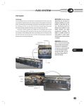
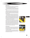
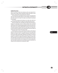
Fuel System Fuel System The Vision’s fuel tank is mounted in the rear overhang between the frame rails and is made of 12-gauge (HRLCCQ–T125) aluminized steel. The fuel system meets the requirements of Federal Motor Vehicle Safety Standard (FMVSS) 301, Fuel Systems Integrity For School Buses. Observe all safety and environmental warnings and precautions in the Introduction chapter of this manual before performing any of the tests and maintenance procedures in the section. [Warning] Blue Bird does not approve or disapprove additions to or modifications of Blue Bird fuel systems. Blue Bird fuel systems are designed and installed to meet federal standards and engine manufacturer’s guidelines. The upfitter or modifier assumes all responsibility for vehicle engine and fuel system if the fuel system is changed or modified. All fuel system components must be a minimum of 7” from any exhaust system component unless properly shielded.. The system includes a flush-mounted inspection plate over the sending unit, mounted in the bus floor and covered with floor covering material. This inspection plate is located near the centerline of the bus and approximately inline with the filler tube neck at the fuel door. The system is designed with either 60- or 100-gallons fuel capacity depending upon wheelbase. The fuel tank is equipped with a ½-inch NPT plug in the bottom. This plug must be removed periodically to allow collected water and sediment to drain. When the discharge is clean fuel, replace the plug. Wheel Base 189 inches 217 inches 238 inches 252 inches 273 inches [Caution] In 2007 diesel engines, use only diesel fuel labeled Ultra Low Sulfer, per the engine manufacturer’s specifications. In Caterpillar, use oils meeting API CJ-4 or Caterpillar ECF-3 compliant. See Caterpillar Operation and Maintenance Manual SEBU8083-08 for details. In Cummins, use oils meeting API CJ-4/SL and Cummins Engine Standard CES-20081. See Cummins Owners Manual ISB 6.7L CM2150 for details. 625 Gallons / Liters 60 / 227.12 60 / 227.12 60 / 227.12 100 / 378.54 100 / 378.54 All fuel system lines and components must be secured a minimum of 7 inches (178 mm) from any exhaust component. Do not repair a damaged fuel line; replace it. The number of clamps required to secure the fuel lines is dependent upon the wheelbase of the bus. When removing a clamp, ensure it is replaced in the proper position. Check with your Blue Bird Distributor for replacement fuel lines. Wheelbase 189 217 238 252 273 Number of Clamps 6 7 8 8 9 L 1 service manual Fuel System Supply Return Loom 626 Fuse Fuse Supply To Engine Plug Fuse Hold fitting with wrench adjacent to fittings being installed to engine. Drain Tank Vent Fuel Sender Fill Vent Not Used Supply 60 Gallon Return From Engine Fitting has a copper gasket which seals against male flares on engine fittings. This gasket must be installed to prevent leaks. Fitting Placement Detail Fuse Fuse Plug Fuse Drain Plug Fuel Sender 100 Gallon Fitting Placement Detail L Fill Vent Not Used Supply 0087409 Tank Vent fuel system Fuel System Assembling Fittings 1. Cut tubing squarely. Maximum of 15° angle allowable. (Use of Parker tube cutter PTC-001 is recommended.) 2. Check that port or mating part is clean and free of debris. 3. Insert tubing into fitting until it bottoms on seat. 4. Tighten nut with wrench until one thread remains visible on the fitting body. (This will allow for a number of remakes.) Or, turn down the nut until finger tight; then tighten as indicated below: tube size 1/4 3/8 & 1/2 5/8 & 3/4 turns beyond hand-tight 3 4 3 1/2 When installing item #10, Tighten one turn beyond finger tight. Then Continue turning to orient barb. 627 L 1 service manual Fuel Filters 628 L The fuel/water separator and primary fuel filter is located just forward of the rear axle, on the inside of the left hand frame rail on the driver’s side. This separator must be drained daily to ensure the fuel is clean and free of water, as it enters the secondary fuel filter. The fuel/water separator and primary filter cartridge (Part Number R90-BB-02) must be changed, at a minimum, at prescribed intervals dictated by the Level 1 Preventative Maintenance Schedule established by Caterpillar. This interval is 11,000 miles (17,700km) or 1,100 gallons (4150 L) of fuel consumption, or 250 hours of engine operation or 6 months; whichever is the first to occur. The spin on filter cartridge replacement is R90-BB-02. This is a 30-micron PRIMARY filter; therefore, secondary/final filtration is required before the fuel reaches the engine. The filter cartridge must be replaced immediately to avoid contamination of the fuel system. Contaminated fuel may make it necessary to change this filter cartridge at any time, not only at scheduled intervals. The secondary fuel filter is located on the left-hand (driver’s) side of the engine, on a mounting bracket just behind the air compressor. This filter must be changed on the PM Level 1 schedule as well. Just one tank of contaminated fuel can cause this filter to need change without regard to the schedule. The secondary fuel filter is also a spin-on canister type filter cartridge that requires periodic maintenance. The replacement filter cartridge (Blue Bird Part Number 0060586) must be replaced periodically. The Level 1 Preventive Maintenance Schedule established by Caterpillar dictates this period. This interval is 11,000 miles (17,700km) or 1,100 gallons (4150 L) of fuel consumption, or 250 hours of engine operation or 6 months; whichever is the first to occur. See appropriate Caterpillar publication for details. The new spin-on filter should not be filled with fuel. This could introduce contaminants into the engine. Prime the fuel system in accordance with instructions in the Caterpillar Operation and Maintenance Manual. fuel system Fuel Level Sending Unit The Fuel Level Sending Unit is mounted in the top of the fuel tank. An access plate located in the floor center aisle provides access to the sending unit for testing and replacement. An electrical terminal in the top center of the sending unit receives signal voltage from the instrument cluster. A ground terminal near the outer edge of the sender connects to ground via the chassis harness. The signal current passes through a mechanical variable resistor, which is actuated by the sender’s float arm. As the float rises and falls with the level of fuel in the tank, it varies the resistance of the unit from 0~3 ohms when the float arm is at its lowest (empty tank) to 85~90 when the arm is fully raised (full tank). This resistance is monitored by the control module of the instrument cluster, which registers it as a percentage and passes it to the fuel gauge. Testing the Fuel Level Sending Unit A multimeter may be used to check the resistance of the sending unit. If the actual fuel level is known, the sender may be tested witout removing it from the fuel tank: 1. Inside the bus, remove the screws securing the access plate. Remove the plate. 2. Disconnect all wires from the sending unit. 3. Set the multimeter to measure ohms. Connect the positive test lead to the terminal in the center of the sending unit. Connect the negative lead to the outer terminal. 4. Turn on the multimeter and note the resistance. If the tank is full, the resistance should be approximately 85~90 ohms. 0).4 629 ¤Ûhafl To further test the sending unit with it removed from the tank: 1. Remove the screws securing the access plate. Remove the plate. 2. Disconnect all wires from the sending unit. 3. Remove the five hex held bolts which secure the sending unit to the tank. Remove the sending unit, being careful to avoid damaging the gasket. 4. Set the multimeter to read ohms. Connect the positive test lead to the terminal in the center of the sending unit. Connect the negative lead to the outer terminal. 5. Hold the sending unit with its mounting plate parallel to the floor, and the float arm hanging free in the empty position. Turn on the multimeter and note the resistance. With the arm in the lowered (empty) position, the resistance should be approximately 0~3 Ohms. 6. Slowly raise the float arm. The resistance should increase proportionally to the movement of the arm until it reaches 85~90 Ohms at the fully raised (full) position. If the reading is out of range, intermittent or sporadic, replace the sending unit. ¤Ûhafl L fuel system Fuel Tank & Barrier Locate in front set of holes on 60 gallon fuel tank. Locate in front & rear sets of holes on 100 gallon fuel tank. 2 631 (Double Nuts) 0068484 Fasteners thru front two holes 60 gallon fuel tank only. Front & rear holes 100 gallon fuel tank. L 1 service manual Fuel Tank Draining the Fuel Tank Caterpillar scheduled Level 1 Maintenance also requires that the fuel tank be drained of accumulated sediment and water. To drain the fuel tank: 1. Observe all safety warnings and environmental cautions. See the Introduction chapter of this service manual. 2. Remove the drain plug from the bottom of the fuel tank. 3. When only clean fuel is being discharged from the tank, replace the drain plug. Install finger tight. Wipe the exposed threads and apply Loctite 557 with Teflon™ to the exposed threads. Continue to tighten the plug 11/2 turns. 4. Wipe clean and ensure there is no leak. 632 L Fuel Tank Removal 1. Using the drain plug in the bottom of the tank, drain the fuel into suitable containers. Loosely install the plug to prevent entry of debris. 2. Place a suitable support device under the tank. 3. Remove 6 hexhead screws from the filler tube cover. 4. Remove 4 bolts from the front tank guard. 5. Remove 4 bolts from rear tank guard. 6. Remove 2 bolts from each end of each tank support. Lower the tank carefully until it is possible to remove the fuel lines and wiring from the top of the tank. There is a loop of approximately 18 inches (457 mm) slack at the top of the tank for this purpose. 7. Remove all fuel lines and the filler tube. Carefully cover each opening as it is opened, to prevent con-tamination. 8. Remove the sender wiring. fuel system Assembly of New Fuel Tank 1. Position the new fuel tank on the support rails. 2. Install the tie-down straps. 2 bolts each end [Warning] Ensure there is protective webbing between the straps and the fuel tank, and between the fuel tank and the support members. There must be no metal-to-metal contact. 3. Install overflow fitting in 2 places. Tighten the fittings finger tight; then apply a bead of Perma-Lok™ LH-150 (or equivalent) thread sealant around the ex-posed threads. Then tighten 2 turns further, using an appropriate, open-end wrench. Do not use an adjustable wrench. Ensure the barbs of the fittings are directed at the nearest edge of the fuel tank and in the direction of the filler tube. 4. Install an 18–20 inch (458–508 mm) length of tubing to direct fuel overflow past the frame rail. 5. Install the return line 90° fitting finger tight at the appropriate opening. Tighten the fitting finger tight, and then apply a bead of Perma-Lok™ LH-150 (or equivalent) thread sealant around the exposed threads. Then, tighten 2 turns further using an appro-priate, open-end wrench. Orient the flange thread toward the outboard edge of the fuel tank and in the direction the filler tube runs. 6. Install the supply line 90° fitting at the appropriate fuel tank opening. Tighten the fitting finger tight. Then apply a bead of Perma-Lok™ LH-150 (or equivalent) thread sealant around the exposed threads, and tighten 2 turns further using an appropri-ate, open-end wrench. Orient the flange thread toward the outboard edge of the fuel tank and in the direction the filler tube runs. 7. Install the 45° elbow vent fitting finger tight into the appropriate opening in the fuel tank. Apply a bead of Perma-Lok™ LH-150 (or equivalent) thread sealant around the exposed threads. Tighten 2 turns further using an appropriate, open-end wrench. Orient the flange thread toward the outboard edge of the fuel tank and in the direction the filler tube runs. 8. Install the tubing adapter into the 45° elbow vent fitting. Tighten finger tight. Apply a bead of thread sealant Perma-Lok™ LH 150 and tighten 1 1/2 flats further. Tank Support 633 L 1 service manual Fuel Tank Installation Installation of the fuel tank is accomplished in the reverse order of the removal instructions above. 1. Position the fuel tank on the tank supports. 634 L [Warning] Ensure there is protective webbing between the straps and the fuel tank, and between the fuel tank and the support members. There must be no metal-to-metal contact. 2. Loosely attach one end of the tank tie down straps. 3. Wrap the tie down straps over the fuel tank and loosely install the other side. 4. Ensure the tank is properly oriented. The front is the end of the tank with the hose fittings. 5. Position the front tank guard and install it to the front tank support. Torque 3 bolts (200) to 36–52 Ft lb (48.81–70.50 Nm). Use new lock nuts. 6. Position the rear tank guard and install it to the rear tank support. Torque to 36–52 Ft lb (48.81–70.50 Nm). Use new lock nuts. 7. Position the fuel tank beneath the chassis. 8. Raise the tank to a level where it is possible to install the fuel lines and wiring. Clean sender wiring termi-nals prior to assembly. Protect the sender terminals with heavy grease. 9. Torque hose clamps to 45 In lb (5.08 Nm). Worm gears and drive hex or slot should be oriented toward the top for accessibility. 10. Lift the fuel tank into position. 11. Install the 4 bolts in the front tank guard. Use a flat washer on each side of the installation. Use a new locknut. Torque to 36–52 Ft lb (48.81–70.50 Nm). 12. Install the 4 bolts in the rear tank guard. Use a flat washer on each side of the installation. Use a new locknut. Torque to 36–52 Ft lb (48.81–70.50 Nm). 13. Install the 2 bolts at each end of each tank support. Use a flat washer at each side of the installation. Use new locknuts. Torque to 40–58 Ft lb (54.25–78.64 Nm). 14. Ensure the fuel tank is centered, front to rear and side-to-side. 15. Tighten the first nut on each tank strap to 40 Ft lb (54.23 Nm). Then, while holding the first nut, torque the jam nut to 40 Ft lb (54.23 Nm). 16. Install the drain plug in the bottom of the fuel tank finger tight. Then, apply a bead of Loctite ™ 557 with Teflon™, or equivalent, to the exposed threads. Continue to tighten 2 full turns. Wipe clean. fuel system Accelerator Control, Electronic The Vision’s throttle control regulates engine speed not by direct mechanical linkage, but by electronically communicating the position of the pedal to the engine’s Electronic Control Module (ECM). The ECM in turn controls the engine’s fuel system to adjust engine speed. When the pedal is pressed, its lever arm rotates a spring-loaded mechanism inside the throttle assembly’s upper housing. Attached to the side of the housing is an electronic position sensor which varies a signal it sends to the engine ECM. The signal modulates according to the position of the rotating part of the pedal assembly. Being electronic, the accelerator is mounted entirely inside the bus, with no part of it extending through the firewall. The assembly is not rebuildable; therefore, it must be replaced as a unit if damaged or faulty. The pedal position sensor requires no adjustment, and is not rebuildable. However it is replaceable as a separate unit from the pedal assembly (Blue Bird kit # 0064032). Throttle Control Throttle Position Sensor The throttle position sensor receives a +8 volt DC supply voltage from the engine ECM, drawing less than 40mA of current. It’s electonic circuitry senses the accelerator pedal position, and generates an output signal which communicates the throttle position back to the ECM. The output signal conveys its data by means of pulse width modulation (PMW), a method by which the wave form of a pulsating DC current signal may be altered in order to convey a signal. Because of its fundamentally on/off nature (square wave form) PWM is particularly well-suited for communication between digital control devices and microprocessors. Pulse Width Modulation Pulse width modulation varies the width of the positive crest of each wave of current. Thus, in pulse width modulation, both the voltage (amplitude) and wave length (frequency) remain constant, while the duration of the positive pulse (pulse width) varies. The longer the duration of the pulse, the higher the percentage of the total wave length it occupies. For this reason, pulse width is measured as a percentage of the wavelength. The percentage is refered to as the duty cycle. In typical applications, the signal frequency is quite higher than the response rate of the load device. The on/off pulses therefore tend to be “smoothed out” or averaged over time while the load operates. The net result is the appearance and behavior of varying output voltage, even though the voltage of the pulses is constant. 635 Accelerator Pedal Assembly Throttle Position Sensor Deutsch Connector Located just above the accelerator position sensor. L 1 service manual Pulse Width Modulation Several components on the Blue Bird Vision employ pulse width modulation rather than mechanical rheostats or resistors These include the acellerator pedal, daytime running lights, and instrument lighting. This illustration explains the basic principle of Pulse Width Modulation. Uniform Square Waveform In this unmodulated wave: Wavelength (and therefore Frequency) is constant. Amplitude (wave height) is constant. Pulse Width (the positive portion of the wave) is constant. Note that in this example, the Pulse Width occupies 50% of the total wavelength. Pulse Width Modulation (PWM) In a PWM circuit, information is conveyed by varying the percentage of total wavelength which is occupied by the Pulse Width. Wavelength (therefore Frequency) is constant. 636 L Amplitude is constant. Pulse Width varies. Note that now, the Pulse Width varies independently of Wavelength. The Pulse Width-toWavelength ratio is expressed as a percentage and is referred to as Duty Cycle. fuel system Auto Calibration The ECM is programmed to automatically re-calibrate its responses to the throttle position sensor signal each time the ignition is turned on. Initially, the ECM interprets a 22% pulse wave as a call for low idle, and a 75% pulse wave as full RPM. During the normal-use cycling of the accelerator pedal, the ECM adjusts its calibration, resulting in a broader duty cycle range in which 10-22% signals idle and 75-90% signals full RPM. This process results in a slight, but noticable, change in the throttle pedal’s “sensitivity” until the auto-calibration is completed. During this time, the Driver may notice that full RPM is achieved before the pedal is fully depressed, and/or that more pedal movement is required to raise engine RPM above idle. This condition is normal during the power-up and auto-calibration period. Testing And Troubleshooting The acellerator installed on the Blue Bird Vision produces a signal which meets Caterpillar’s specs for PWM input throttle signal. Caterpillar provides diagnostic tests and codes in their ET and PocketTech diagnostic software. The output of the throttle assembly may also be tested using a multimeter which is capable of measuring a PWM duty cycle, as follows: 1. Inspect all electrical connectors and wiring harness associated with the accellerator. 2. With the ignition off, disconnect the Deutsch electrical connector located just above the accelerator pedal. 3. Turn the ignition on and and check for voltage from terminal A of the vehicle wiring harness to vehicle ground. Voltage can be checked by using Caterpillar’s breakout test lead. This should indicate that +8 VDC is being delivered by the ECM to the harness connector. If Breakout the voltage is out of range: Lead Caterpillar Breakout 637 Breakout Lead plugged inline between ends of position sensor’s Deutsch connector. Checking Supply Volt- • Check the integrity of the vehicle wiring harness from the connector to the ECM. Repair as necessary. • If connections and harness test satisfactorally, the problem may be due to a damaged ECM. Refer to Caterpillar troubleshooting guidelines. 4. Turn ignition off. Connect the breakout test lead as follows: 4.1 Connect the breakout lead inline with the accelerator wiring harness. Meter set to read Volts DC. Connected to positive and negative plugs of Breakout Lead. L 1 service manual 4.2 Connect the red lead of the meter to terminal C of the breakout test lead (accelerator pedal position ; white circuit). Checking Duty Cycle 4.3 Connect the black lead to terminal B of the breakout test lead (accelerator/switch sensor common; black circuit). 5. Set the meter to measure duty cycle percentage. Turn the ignition on. 6. Check the duty cycle readings with the accelerator at idle and at full RPM position. Compare the readings to the values shown here: 638 ith the Position Sensor attached to the Accelerator Pedal Assembly, W readings should be: Idle: 10–22 % Full Throttle: 75–90% If the Position Sensor is removed from the Accelerator Pedal Assembly, readings should be: Idle: ≤10 % Full Throttle: ≥90% If duty cycle values are determined to be out-of-range, replace the accelerator position sensor and/or the accelerator pedal assembly. 7. Slowly move the accelerator pedal from idle to full throttle position while observing the meter. Duty Cycle percentage Breakout Lead should increase and decrease proportionally to the movement of the pedal. If it does not, replace the accelerator position sensor and/or the accelerator pedal assembly. Pedal Fully DeRed lead connected to white PWM signal wire. Meter set to display Duty Cycle. Pedal at Idle L fuel system Testing And Troubleshooting (Cummins) The Cummins accelerator pedal incorporates two Throttle Position Sensors to provide the required input to the engine ECM. These components are non serviceable and should not be removed from the accelerator assembly or you could risk voiding the warranty. Each component has three wires going through a weather-pak connector and can be tested individually for proper operation. Throttle Position Sensor Coil Resistance The Throttle Position Sensor provides the engine an analog signal instructing it to increase or decrease RPM based on the position of the accelerator. This is done with a three wire potentiometer. The sensor is provided a continuous 5V DC (pin B27) and a ground (pin B28) by the engine ECU. As the accelerator pedal is depressed, the throttle position sensor will relay its position to the engine (pin B35). The throttle position sensor can be tested by the following: Disconnect sensor plug and meassure resistance on accelerator side of connector between: • Pins C and A. (Supply and Return) Value should be between 2000 and 3000 ohms. • Pins C and B. (Supply and Return) Released pedal value should be between 1500 and 3000 ohms. • Pins C and B. (Supply and Return) Depressed pedal value should be between 200 and 1500 ohms. 639 Resistance should decrease proportionally as pedal is depressed. Released pedal resistance minus depressed pedal resistancemust be greater than 1000 ohms. [CAUTION] Do not attempt to adjust or repair throttle position sensor or idle validation sensor. Warranty will be voided. Should the accelerator fail to meet specifications the entire pedal must be replaced. C5 Driver’s Control Module Throttle Sensor #1 THROTTLE RETURN THROTTLE SIGNAL #1 THROTTLE POWER SENSOR POWER THROTTLE SIGNAL #2 SENSOR RETURN WHITE BLACK RED YELLOW GRAY GREEN A B C D E F PINK BROWN BLACK BROWN GRAY BROWN 27 26 28 29 30 31 PINK BROWN BLACK BROWN GRAY BROWN C701 Engine Harness 7 8 6 20 13 5 Engine Control Module (ECM) PINK BROWN BLUE BLUE BROWN TAN 28 THROTTLE RETURN 35 THROTTLE SIGNAL #1 27 THROTTLE POWER 26 SENSOR POWER +5 VOLTS 25 THROTTLE SIGNAL #2 22 SENSOR RETURN Throttle Sensor #2 L