1
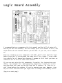
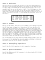
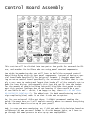
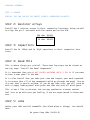
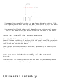
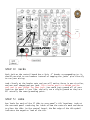
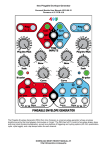
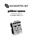
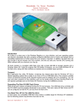
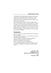
seqSQUARED
The Analogue Pattern Generator
ASSEMBLY MANUAL REV.1
Brought to you by:
hexinverter.net
Introduction
ABOUT THIS MANUAL: Anywhere you see text coloured like this indicates a
hyperlink! Click it to go to the corresponding page/website!
Greetings! Thank you for your interest in/purchase of seqSQUARED. It is my
hope that you find whatever creative tool it is you are looking for in this
design.
This project was made possible through the excellent online synth DIY community and their trustworthy attitudes. As project funding was acquired
through pre-orders, it wouldn’t have been possible without the support of
everyone that committed to pre-ordering. Thank you for making this happen!
This is the build manual for this project, and will walk you through assembling your seqSQUARED module. You can find the user manual at the
hexinverter.net project site.
DISCLAIMER: I know that I write a lot, but it is FOR A REASON! Please, try
to read all that I have written here. I have spent many precious hours
that I would have much rather spent designing new devices to develop this
written manual so that others can build their modules smoothly! I know
most folks want to just skim over the manual, but chances are if you have
a question about the assembly or design of this module, I have already answered it here!
If I have not, my apologies for wasting your time. Please email me at:
hex[at]hexinverter.net or visit the Muffwiggler forum and we will resolve
your issue!
PLEASE NOTE: seqSQUARED is an intermediate/advanced project and thus I do
not recommend it for total beginners. There is a lot of panel wiring if
you are not making the eurorack version, and if something goes wrong it
is not the easiest to troubleshoot. That being said, drop me a line via
email if you need assistance: hex[at]hexinverter.net, or stop off at the
Muffwiggler forums and find the seqSQUARED help thread. Maybe someone else
will know the answer for you and save me some valuable time to work on new
projects with :)
It is assumed that you know how to solder reliably and have built a few
projects successfully already, so that will not be detailed here.
If you need some help learning how to solder, check out the introduction
in the sympleSEQ build manual.
Frequently Asked Questions
The FAQ can be found in the USER MANUAL.
Getting Started
Before you begin, I recommend thoroughly examining your kit’s contents
and comparing to the bill of materials to ensure that you have all of the
parts to complete your build. While quite rare, I occasionally make a mistake when packaging a kit. I am, afterall, only human (unfortunately...
haha), and thus sometimes fall victim to human error. If you spot a component missing, please, email me and we will resolve this matter for you!
Now, settle down in your workspace and let us get started!
Logic Board Assembly
I recommend having a computer with this manual and the bill of materials
beside you for the assembly. You can always print this manual as well, but
think about the environment before you do that. If you can, use a computer!
Begin by rounding up your components and PCBs. We’ll start with the logic
board since this is pretty much the same for all kit types. I’m not showing a whole lot of images here because I assume at this level you have encountered all of this at least once before!
If you are not using the kit components I provide, the instructions may
differ. For example, the .1µF decoupling capacitors I supply are axial,
and therefore are lower on the PCB than the IC sockets, so I say to install them before the sockets. If you’ve sourced your own, however, they
may be taller and therefore you might want to change the assembly order.
(begin on next page)
STEP 1: Resistors
The first step is to install the resistors, as per the value markings on
the board. I have designed the board’s silk screen so you should be able
to simply look at the board and tell where everything goes. This is all
standard stuff for you at this point, right? :) Use a multimeter to identify the values if you are lazy, or you can use your eyeballs with my
handy chart I’ve made for you here (note that these colours are for the 1%
variety I include in the kits...if you sourced your own parts, you’re on
your own!):
100k:
10k:
47K:
1k:
68k:
BROWN
BROWN
YELLOW
BROWN
BLUE
BLACK
BLACK
PURPLE
BLACK
GREY
BLACK
BLACK
BLACK
BLACK
BLACK
ORANGE
RED
RED
BROWN
RED
BROWN
BROWN
BROWN
BROWN
BROWN
STEP 2: Diodes
Next up is the diodes. There are a lot of diodes in this design to protect
the PIC from input voltages (Vinput) that do not fall into the 0<Vinput<5V
range that the microcontroller can handle. I certainly could have used
some opamp trickery to scale voltages down until the PIC microcontroller
was happy with them, but then you would be soldering a bunch of opamps and
resistors instead. Either solution works well, but since a 12V CV range
for the CV inputs on seqSQUARED wouldn’t really be any more useful than
the 0->5V range it can handle, I did not really see the point in spending
more time with it. I also wanted to learn about clamping diode setups and
thus chose to have fun with that solution instead :)
All of the diodes on the logic board are BAT85 Schottky diodes. There are
24 in total. It is important you pay very careful attention to their orientation as they are in fact polarity sensitive!
STEP 3: Decoupling capacitors
Install the 11x 0.1µF capacitors in their respective locations.
STEP 4: Quartz Resonator
Install the 20MHz crystal (X1) resonator in its place beside IC1. Be careful not to overheat!
STEP 5: Resistor Arrays
seqSQUARED uses a special type of component called a resistor array. Even
if you are a seasoned electronics person, this may be a new component for
you to work with! It was for me when I designed this project!
It is only with great scrutiny that I chose to use these devices in this
project, because they are not something everyone has in their parts bin.
The alternative, however, would be to bend the leads on, install and solder nearly 50 more resistors than you already have! This would simply be
too much to handle, for you, and for me -- since my retail volume is so
low that I have to assemble these by hand for retailers to sell!
Enter: the resistor array. These little guys are 10 pin SIPs (“single inline packages”) that contain various configurations of resistors. The types
we are using here are of two varieties:
Bussed Array: These contain 9 equal value resistors that are connected to
a common pin (ground in our case). These are extremely useful for things
like arrays of LEDs that are the same colour (and thus require the same
resistor value to set the brightness), and pull-down resistors.
ISOLATED ARRAY: These arrays contain 5 individual resistors in a single
package that work the same as single resistors. They have two connection
points per resistor.
WHEN INSTALLING YOUR RESISTOR ARRAYS: Be VERY mindful of the orientation.
These devices ARE polarized! If you look at the writing on the array,
there is a solid dot marking pin 1 of the array. Pin 1 is marked on the
circuit board with a SQUARE PAD. Make sure you line these up or seqSQUARED
will not work properly!
The resistor array’s value is marked using a code, much like ceramic capacitors. Here are the codes for the arrays used in this project:
150
1k
20k
39k
100k
ohm:
ohm:
ohm:
ohm:
ohm:
10B151
10B102
10A203
10A393
10A104
STEP 6: IC Sockets
I highly recommend the use of IC sockets. Without them, if you burn out
a chip due to faulty wiring or something, you are in for a whole heap of
trouble trying to desolder it and replace it! For that reason, my kits include very nice, gold-plated round machined pin sockets.
I encourage you to install all of the sockets in their holes at once, then
without soldering them yet, place something flat on top of the sockets (I
use a piece of cardboard cut to the size of the PCB). Grab this with your
hand, keeping pressure on the sockets through the flat material, and flip
the board over. Now, you can carefully remove the flat piece of material
and use the flat work surface to level all of the IC sockets. This greatly
speeds up the process and does not require bending the sockets’ legs to
make them stay in while you flip the board over.
STEP 7: Ceramic Capacitors
Install the two 33pF ceramic disc capacitors C1 and C2 beside the microcontroller.
STEP 8 (eurorack only): Power Header
Install the shrouded power header, being careful to follow the polarity of
the notch on the board silkscreen. This is a standard Doepfer compatible
layout, but I recommend verifying it yourself before even thinking of applying power to the board!
STEP 9: Random Bits
Install the three 10uF electrolytic capacitors (silk-screen shaded part
= NEGATIVE), the LM7805 regulator, and the two 2N3906 transistors, being
careful to obey polarity and not to overheat components.
If you are building a different format than eurorack, you can add power
wires now. There are handy arrows with markings by the power pads that
show you which pad is which!
You are now finished assembly of the logic board!
**Do not install the headers, or the ICs in their sockets yet. We will do
that later.**
Control Board Assembly
This section will be divided into two parts: One guide for eurorack builders, and another for builders who are using panel mounted components.
You might be wondering why you still have to build the eurorack control
board using flying wires to your panel components, instead of having a special board made specifically for universal formats. I thought about making an extra control board specifically for universal builders that is simply a very easy to understand layout that broke all of the controls out to
pads for easy wiring. Unfortunately this just did not fit into the budget
for the amount of people building universal kits/PCBs that opted to support this project (perhaps due to not knowing if there would be a panel available or not -- which, I am happy to say, there will be one from
Re:Synthesis eventually!). The added cost (in both manufacturing and design complexity/time) made it so that it was not an option.
So, for you universal folks out there, I HIGHLY recommend reading the
guide I present here as I will explain exactly where to connect everything
on the control board to wire up to your panel!
And, in case you were wondering, no, I did not make this decision based on
selfishness! My own personal format is 4U with banana jacks, so I have to
go through the same process to wire up my own seqSQUAREDs.
Eurorack Assembly
STEP 1: Diodes
Install the two 1N4148 (or 1N914) diodes, observing polarity.
STEP 2: Resistor Arrays
Install the 3 resistor arrays in their respective locations, being careful
to align the pin 1 indicator with the square pad on the PCB.
20k ohm: 10A203
39k ohm: 10A393
1k ohm: 10B102
STEP 3: Capacitors
Install the 5x .001µF and 1x .01µF capacitors in their respective locations.
STEP 4: Read This
This is where things get critical. These next few steps can be viewed as
one big step: “Install the Panel Components”
It is important that you DO NOT SOLDER ANYTHING UNTIL I SAY SO if you want
to have a neat panel in the end.
It is also crucial that you take your time and inspect your work repeatedly to ensure that all of the components which go through the panel line up
in a way that is mostly uniform. If you do not take care, you will wind up
with a crappy looking panel with jacks and LEDs and such all misaligned.
This is how I like to do mine, but you may synthesize a better method.
Feel free to go with your gut feeling if you are experienced in these matters.
STEP 5: LEDs
Gather your LEDs and LED standoffs (the black plastic things). You should
have:
8x green Step LEDs (SLED1-8)
4x yellow Source LEDs (PLED1-8)
5x red LEDs (CLED, KLED, ELED, PG1LED, PG2LED)
Prepare them for insertion into the board by installing each of the LEDs
into a spacer.
Don’t mix your LEDs up! I recommend inserting them in their place on the
control board right when you install them in the spacers. They are all
clear so you would have to light each of them to test their colour if they
get mixed up. You can do this with a multimeter on diode test if you do
mix them up.
Once the LEDs are all in the board, bend their legs, but DO NOT SOLDER
THEM YET!
STEP 6: Jacks
With your LEDs just dangling in their places, gather up your 14 jacks and
insert them into the board where they are supposed to go. Once again, do
not solder them in yet.
STEP 7: Push Buttons
Install the 2 white push buttons into the SW.RST and SW.STEP holes in the
board, making sure the flat side is aligned with the silk screen legend.
Install the green push button into the SW.EDIT position. Do not solder any
of the switches yet.
STEP 8: The “Tricky Part”
Now, with everything but the potentiometers installed and loose in the
board, take your eurorack panel and slowly drop it down over the components. This is the tricky part -- you now have to flip the board back over
without all of the parts falling out (or, at least, most of them still in
there). When you have done that, take your soldering iron and tack ONLY
ONE LEG of each component in place. Once they are all tacked, flip the
board back over and inspect your work:
Is everything aligned well when you look at the panel from the front?
When you look level at the board from the side, are all of the components
sitting flush against the board?
Are all of the LEDs at the same height?
Do the push button switches actuate freely when pushed through the panel?
Chances are, some of your components probably fell out, or are lop-sided
or uneven. The push buttons may be rubbing against the panel holes.
Now, you must take care to adjust components one at a time by re-heating
the single solder “tack” joint you made, until all of the installed components are satisfactorally placed.
Once you are satisfied with the position of everything, solder all of the
contacts to permanently fix the components in place.
STEP 9: Prepare the Potentiometers
If you have ever designed a project before, you probably know just how
hard it is finding the perfect potentiometers for your design.
Please keep this fact in mind as you cut the included pots’ shafts! -“Wait! What!?”, you say -- Yes. You unfortunately have to cut the shafts
down to length so the knobs sit at the correct height.
Unfortunately nobody seems to want to stock the correct length pots for
80% of the knobs they sell, so we are forced to deal with this.
The “Big Guys” (aka: Intellijel, Makenoise, etc.) are all able to purchase
directly from the potentiometer manufacturer, I’m sure, so they get to order the perfect sized pots direct. As a very small volume manufacturer I
am incapable of ordering 5000 pots at a time, so bear with me here!
I have carefully chosen what I believe
ing potentiometer available that works
of the options and chose the smoothest
very easy to cut due to the nice, soft
works well for us.
to be the absolute best feelfor this project. I sampled many
feeling pot. It also happens to be
plastic used for the shaft, so that
Measuring from where the black plastic shaft begins (ie: right where the
metal bushing ends), you want to cut the shaft of each potentiometer down
to 13mm (see rendering on next page)
I recommend the use of tin snips, or some heavy duty wire cutters (like,
the big kind you’d never use for the small electronics we do). You could
also use a hacksaw, but that takes much more time.
You may need to file the edges a bit depending what cutting tool you use.
Test fit each knob on the pot before installing the pots in the board.
STEP 10: Install the Potentiometers
Install all of the pots into their respective positions on the control
board. Tack one conductor of each pot with the panel installed, re-adjusting as necessary (just like in Step 8) to ensure they are installed correctly and flush against the board.
Once you are satisfied with their positions, permanently fix them in place
by soldering the remaining contacts.
You are now finished assembly of the control
board!
The universal kit assembly instructions are next, so you can skip ahead
now to the final assembly and testing!
Universal Assembly
STEP 1: Diodes
Install the two 1N4148 (or 1N914) diodes, observing polarity.
STEP 2: Resistor Arrays
Install the 3 resistor arrays in their respective locations, being careful
to align the pin 1 indicator with the square pad on the PCB.
20k ohm: 10A203
39k ohm: 10A393
1k ohm: 10B102
STEP 3: Capacitors
Install the 5x .001µF and 1x .01µF capacitors in their respective locations.
From here on out, I recommend that you solder wires to the control board,
but don’t actually solder them to their corresponding panel components
yet. We’ll do that after the final assembly, before testing.
Wiring Diagram
STEP 4: Jacks
Each jack on the control board has a 2pin .1” header corresponding to it,
should you wish to use headers instead of tapping the jacks’ pins directly
to run your wiring.
Look closely at the header sets and you will notice there is one circular,
and one oval shaped pad per jack. The circular pad is a GROUND and the
oval pad is your SIGNAL for that jack. You could just ground all of your
jacks on the panel if you like, and only run a single ground as they are
all actually the same grounding point.
STEP 5: LEDs
Run leads for each of the 17 LEDs to your panel’s LED locations. Look at
the eurorack panel rendering for ideas of how the controls work and where
to place the LEDs. On the control board, the flat edge of the LED symbol
indicates the negative lead of the LED.
STEP 6: Push Buttons
Run leads for the three push buttons. There are 4 pads for each, but they
are really just two conductors connected inside the switch (2 pins per
switch conductor).
I have marked the pins that are the same point (connected together) with a
line on the PCB silkscreen. Connect one lead to each line. It doesn’t matter which pin on the line you select. Run these lines to your momentary
switches on your front panel!
STEP 7: Potentiometers
You must pay close attention here, because, if you wire a pot backwards,
you will have backwards the functionality you are expecting to have (as
they are wired as basic voltage dividers).
The pots used for the eurorack version are actually mounted upside down.
This makes it a bit confusing for you (sorry!).
When you look at your panel mount potentiometer with the shaft facing you,
you have 3 leads: 1, 2, 3
To match your panel mount pots to the pads on seqSQUARED, simply look at
the pots upside down (so the “seqSQUARED” text on the control board is upside down). Now, the pin numbers match your panel mount pots perfectly!
I highly recommend soldering in colour-coded sets of wires for the pots.
For example, you could have a 3 conductor setup, where:
Pin 1: Green
Pin 2: Yellow
Pin 3: Orange
Now, when you are actually soldering the wires to the pots on your panel,
you know what pin each wire connects to, instead of having to think about
it!
You are now finished assembly of the control
board!
Go to the next page to do the final assembly and testing!
Final Assembly and Testing
You’ve built both of your seqSQUARED boards now. Awesome! Now it is time
to connect them together and begin testing your work!
Inspect Your Work
Don’t even think about going ahead until you have thoroughly gone over
your work for solder shorts, missed soldering points, or other defects!
Double check that your power connector is oriented correctly and that you
are not going to connect the power backwards!
Connect the Boards Together
Grab the 1x 40pin male and 2x 20pin female .1” headers, and snap the 40
pin one in half.
Decide which board you want to have male headers, and which you want to
have female.
Now, lock the headers together in twe male/female pairs, the same way they
will be when the boards are connected together.
Place the header pairs in the holes on the BOTTOM of the logic board (the
wrong way from all of the other components) an then place the control
board on top of that, allowing the header pairs to be sandwiched between
the two boards.
Now, try to ensure the headers are straight as you solder them in place on
the boards from both sides.
This process of locking them together before soldering will mean that they
are soldered such that they can be removed easily if the need arises!
Testing Your Work
If you are building a universal module, feel free to attach your flying
leads to the panel components now.
(next page)
Test the LEDs
I recommend taking a multimeter (or a current limited DC power source -don’t blow the LEDs!) and testing each LED to make sure it is correctly
wired/not burned out from heat. It is possible that you have damaged one
or more LEDs from soldering temperatures. If one doesn’t light up, replace
it!
Power up Test
This is it! Almost there!...
WITHOUT ANY OF THE ICs INSTALLED IN THE SOCKETS, power up your boards and
take some measurements, as per the following charts. If anything is off,
here, you know you have screwed up or reversed the power leads, and thus
save yourself the trouble of blowing a bunch of ICs ;)
With your multimeter on DC voltage, measure these points (referenced to
ground of course -- clamp your ground probe to ground for all of these
tests and then just probe around with the positive probe) and ensure the
voltage is approximately equal to the expected values...
Test 1: 5V Supply
Pin 3 of IC8 should show roughly 5V.
Pin 11 of IC1 should show roughly 5V.
Pin 14 of IC7 should show roughly 5V.
Test 2: +V Supply
Pin 14 of IC5 should show roughly your +V supply voltage.
Pin 4 of IC2, IC3 and IC4 should show roughly your +V supply voltage.
Pin 8 of IC6 should show roughly your +V supply voltage.
Test 3: -V Supply
Pin 11 of IC2, IC3 and IC4 should show roughly your -V supply voltage.
Pin 4 of IC6 should show roughly your -V supply voltage.
That’s it!
If any of the above tests failed, you have something wired/solder
incorrectly or your power reversed. Correct this problem before continuing
if so!
You can now install the ICs in their sockets, and
power up!
If all goes well, upon powerup, the Step 1 LED indicator should be lit,
and the Source A indicator lit as well.
Carefully touch
are warm/hot to
all is cool and
guide to see if
the ICs with your finger to test for heat. If any of them
the touch, power down immediately and check for shorts. If
fine, go to the user manual and test using the quick start
your module works!
If it doesn’t, make sure to go back and carefully check your work, and
read the troubleshooting guide in the USER MANUAL!