1
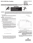
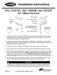
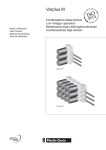
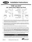
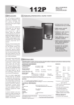
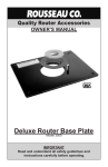
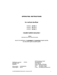
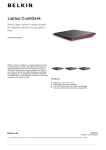
Fast’s®
Couplings
Service Manual
Form 1900-01
Revised October 2007
Kop-Flex, Inc., P.O. Box 1696, Baltimore Maryland 21203, 410-768-2000
Kop-Flex Canada, Ltd., 19 Meteor Drive, Rexdale, Ontario, Canada M9W-1A3, 416-675-7144
Emerson Power Transmission
!
WARNING
High voltage and rotating parts may cause
serious or fatal injury.
Turn off power to install or service.
Operate with guards in place.
Read and follow all instructions in this manual.
Fast’s
Identifying Features
Fast’s
Forged Steel #11/2 to #7
Model B #1 to #31/2
Cast Steel #8 to #30
Boss on
Sleeves
Integral End
Rings
Smooth Sleeves
Hex Head Bolts
Non-rabbeted Flanges
Hex Head Bolts
Non-rabbeted Flanges
Installation and Alignment
Instructions
Recommended Lubrication
Kop-Flex® KSG Coupling Grease
These instructions generally apply to
forged steel, model B, and cast steel
couplings. For modifications and
variations of these couplings, this
sheet may be supplemented by
special instructions supplied with the
couplings. Always use caution when
working on rotating equipment. Be
sure to lock out the starting switch of
the prime mover so the equipment
cannot be star ted until work is
complete, checked, and personnel are
safely away.
This
grease
is
specifically
compounded for standard couplings to
provide improved lubrication and
resistance to centrifugal separation.
When KSG grease is used, lubrication
intervals may be extended, based
upon operating experience. Balanced
couplings or others operating at
speeds above 3500 rpm can benefit
from Kop-Flex KHP coupling grease.
Both KSG and KHP coupling greases
are available from Kop-Flex or
authorized distributors of Kop-Flex
power transmission products.
If the coupling is mounted on a
reciprocating machine, or if recurrent
reverse loading is experienced, a
heavy viscous lubricant, similar to
Texaco® Crater Compound #0 or Gulf
Lubecoat #0 may be required for
damping characteristics.
Oils
Use a mineral oil of a viscosity no less
than 150 SSU (Saybolt Seconds
Universal) and no more than 1000
SSU at 210 F. Example: SAE 140 Gear
Oil (AGMA #8).
Lubrication Interval
Coupling lubrication is critical. The use
of proper and sufficient lubricant is part
of a successful installation. Lubricants
should be checked to see the proper
level is maintained and that the
lubricant is free of contaminants. If
continual operation periods are
expected to exceed six months, a
coupling grease is recommended. The
coupling should be checked for
lubricant
contamination
and
replenished with the proper volume
every twelve months. Conditions such
as very slow speed, reversing drives,
high heat, and severe environments
may require more frequent lubrication.
Bolted End Rings
Integral End Rings
Note: Do Not use oil in Model B
couplings. The model B is designed
to use grease only.
Hex Head Bolts
Rabbeted Flanges
Other Greases
Alternate lubricating greases should
equal or exceed the specifications for
Kop-Flex KSG and KHP coupling
greases. (Specification sheet 3532 is
available upon request.) Greases
other than KSG or KHP, should meet
these minimum specifications:
Grade: NLGI #1
Base oil Viscosity: Min.:
3000 SSU at 100° F
160 SSU at 210° F
Dropping Point, Min.: 190° F
Four Ball Wear, ASTM D-2266:
.500mm Maximum
Base oil content: 87% Minimum
K36 Factor, ASTM d-4425
KSG: K36= 8/24 = .33
Required:
Rust and Oxidation
Inhibitors
E.P. Additives
The most reliable test of a suitable
lubricant is often the result of user
experience and satisfaction. If a
lubricant has been known to sludge,
separate into heavy components or
dry out, consider the use of Kop-Flex
greases or one meeting the minimum
specifications.
™
Preparation
Check Angular Alignment
Coat the sleeve teeth with coupling
grease. Place the coupling sleeve over
shaft end as shown (for bolted end ring
couplings, first place end ring over
shaft). If using a keyed connection
apply a suitable anti-galling compound
to the shaft. For keyless hub-to-shaft
connections, follow the equipment
manufacturers instructions.
For normal hub separation, use a
feeler gauge at 4 points 90° apart, or
for best accuracy, a dial indicator.
Place keys in shaft keyways with a
snug side-to-side fit, and slight
clearance top to bottom.
Clean the shaft and hub. Straight bored
hubs may be coated with a suitable
anti-galling lubricant. Taper bored hubs
must be installed without lubricant.
Position machines to obtain best alignment. Normal variation should not exceed .001 inches (0.025mm) times
coupling size. Maintain correct hub
separation referring to the “C” dimension shown in tabulations on page 4.
For greater hub separation than standard (such as spacer and floating shaft
couplings), use micrometers or other
suitable alignment fixtures to span the
separation and measure the four 90°
points.
Recheck angular alignment and hub
separation.
Expand hub in an oven until the bore
is substantially larger than the shaft
diameter. Straight bored hubs are
normally bored for an interference fit
of approximately 0.0005 in/in of shaft
diameter. For most values of
interference, this will require a hub
temperature of about 300° (150°C).
Never exceed 600°F (300°C).
To avoid the risk of
explosion, fire, damage to coupling
and equipment, and /or injury to
personnel, do not use an open flame
or oil bath to expand the hub.
Properly orienting the hubs, slip them
over the shafts and keys. Hub faces
are normally mounted flush with shaft
end.
On bolted end ring couplings such as
the Fast’s cast steel, the sleeves are
bolted to the end rings after placing
the gasket between the flanges.
Offset Alignment
Visual Method
Shim one machine and align shafts
using a straight edge until it appears
to be at right angles to the shafts.
Repeat at three additional points 90°
apart.
Coupling Assembly
Check to insure the center flange
gasket (o-ring) is not damaged. Clean
the flange faces and place the gasket
in place. For spacer couplings or other
arrangements, a gasket must be
placed between each set of flanges.
Offset Alignment
Instrument Method
Note: For maximum coupling life, the
Instrument Method of coupling
alignment is recommended.
Attach a dial indicator bracket to one
hub with dial indicator probe
contacting the opposite hub’s
alignment surface. Rotate the hub on
which the dial indicator is attached,
and take readings at 4 points 90° apart.
The offset (TIR) should be less than
.002 inches times the coupling size.
For greater hub separation than
standard (such as spacer or floating
shaft couplings) use suitable fixtures
to span the separation and measure
the four 90 ° points. Shim either
machine until best possible alignment
is obtained.
Recheck angular alignment and hub
separation.
Draw flanges together, positioning
lube holes 180° apart on the model B,
and 90° apart on the Fast’s forged steel
couplings. (Note that the cast steel
coupling has two lube plugs in the
male sleeve only).
Align the gasket with the flange bolt
holes, insert the fitted bolts, lockwashers and nuts. Tighten all fasteners
to the torque value shown on page 4.
Lubrication
Mounting of Tapered Bored Hubs
Select the unheated taper bored hub.
Mount the hub hand tight on its shaft
and lightly rap it with a soft mallet to
establish the initial line-to-line fit. Draw
the hub up an additional distance to
obtain the desired interference fit for
the connection. In some cases the hub
may require heating to achieve desired
fit. (The required amount of axial
movement is dependent upon the bore
diameter and taper angle).
Install the hub retention means (locknut etc.) provided with the shaft, and
securely lock the retainer into place.
For most installations, the hub face will
project slightly beyond the shaft end
after hub pull-up.
The coupling must be lubricated
before operation.
Remove two fittings 180° apart. Rotate
the coupling to place the bottom hole
45 ° off horizontal. Pump or pour
lubricant into the top hole until excess
appears at the bottom hole. Sufficient
lubricant has now been added. (Hand
packing of grease in each half of the
coupling is recommended). After
lubrication, tighten lube plugs to the
specified torque value shown on page
4.
The trademarks Kop-Flex and Fast’s are registered trademarks of Kop-Flex, Inc.
The Emerson logo is a trademark and a service mark of Emerson Electric Co.
Texaco is believed to be a trade name and/or trademark of Chevron Products Company and is NOT owned or controlled by Emerson Power Transmission.
Emerson Power Transmission Corporation cannot and does not represent or warrant the accuracy of this information.
2
© 2002, 2007 Emerson Power Transmission, All Rights Reserved.
Note: Spacer; limited end float;
floating shaft couplings, and some
other styles, require each end to be
separately lubricated.
Recommended Set-up Method for Boring
Lubricant capacities for each size and
coupling style are given on page 4.
Dynamically Balanced
Couplings
CENTERLINE
OF BORE
In addition to the previous instructions,
certain other precautions must be
followed to insure coupling dynamic
balance at assembly.
1. Replace each nut, and lock-washer
on its own bolt as they have been
weight balanced as a set. The set can
be used in any bolt hole. 2. Fit the shaft
keys precisely to fill the keyway with a
tight fit only on the sides. Key weight
should equal the weight of metal
removed from shaft and hub keyways.
3. Position each sleeve with it’s hub;
noting any match marks on either the
sleeve or hub. Keep match marks in
line as final assembly is completed. 4.
Position all other parts such as spacer,
floating shaft, etc., properly aligning
any match marks. 5. Lubricate the
coupling.
Note: Use an adapter plate only with
half-coupling of the same serial
number.
INDICATING
SURFACE
INDICATING
SURFACE
ALIGNMENT DIAMTER
ALIGNMENT FACE
The alignment diameter of the hub should be chucked in the boring lathe and dial
indicated as shown, so that run-out is as near zero as possible. It is essential that
the finished bore be concentric with the two indicating surfaces.
Keyways
Keyways should be cut to give a tight fit on the sides, and slight clearance over or
under the key. Keyways should not have sharp corners. Refer to published AGMA
standards for specific dimensioning of coupling bores and keyways.
Finish Boring and Keyways
Coupling hubs are often furnished with
a “rough stock bore”. This rough bore
is not necessarily concentric to other
hub diameters.
To prepare for boring, set up and
indicate the hub as shown by the
illustration.
Bore sizing and recommended fit:
Finish bore size should be based on
the actual shaft dimension measured,
regardless of whether straight or taper
shaft.
Important Safety Instructions
Before start-up . . . for reasons of safety and to extend shaft coupling
life, follow these requirements.
A light interference fit based on a
nominal interference of .0005 in. per
inch of shaft diameter is suggested,
or refer to published AMA standards.
2. Recheck alignment after all foundation bolts and mechanical connections
are tightened.
Do not exceed an interference fit of
.0012 per inch of shaft diameter for
Fast’s forged steel model B, and for
the cast steel.
5. Only authorized Kop-Flex replacement parts are to be used.
1. Coupling guards protect personnel. All couplings must be covered
with a guard as per OSHA requirements.
3. Make sure all fasteners are properly installed and tightened.
4. Take the time to double check your work.
6. Call Kop-Flex for any clarification or questions.
Alternate fits:
If other than a light interference fit is
desired, please consult the published
AGMA boring and keyway standards,
or contact our engineering department
for specific recommendations.
Disconnect all power before adjusting units.
© 2002, 2007 Emerson Power Transmission, All Rights Reserved.
3
Forged Steel and Mill Motor
Coupling Size
1 1/2
2
2 1/2
3
3 1/2
4
4 1/2
5
5 1/2
6
7
1/ 8
1/8
3/16
3/16
1/4
1/4
5/16
5/16
5/16
5/16
3/8
5/32 5/32 3/16
3/16
7/32
5/16
11/32
11/32
13/32 13/32
Hub Separation - "C" (inches)
Hub Separation - "Cfr" (inches)
1/2
Hub Length - "E" (inches)
Hub Length - "Efr" (inches)
Flange O.D. - "A" (inches)
Grease Capacity
(LB.-OZ)
Oil Capacity
(U.S. Pints)
SAE #140
Bolt Tightening
Torque (Lb. Ft.)
6
7
8 3/8 8 3/8
11
Full Flex
0-6
0-7
0-14
1-6
2-0
3-6
4-1
5-6
Flex-Rigid
0-3
0-4
0-7
0-11
1-0
1-11
2-0
Spacer Only
(per in. of length)
0-2
0-2
0-2
0-3
0-4
0-6
0-8
Full Flex
1/8
3/16 5/16
1/2
3/4
1 1/4
Flex-Rigid
1/16 3/32 5/32
1/4
3/8
Spacer Only
(per in. of length)
.02
.07
.08
Exposed
20
Shrouded
.04
.05
50
18
20 3/4
8-9
11-4
14-14
2-11
4-2
3-13
7-7
0-9
0-13
0-15
1-3
1 1/2
2
3 1/8
3 7/8
5 3/4
5/8
3/4
1
1 1/2
2
2 1/2
.12
.15
.18
.22
.25
.35
100
175
55
110
20
Lube Plug Tigntening
Torque (Lb. Ft.)
12 1/2 13 5/8 15 5/16 16 3/4
165
250
195
20
Full-Flex Coupling
-
50
Model B and Model B Mill Motor
1
1 1/2
2
2 1/2
3
3 1/2
Hub Separation - "C"
Coupling Size
1/8
1/8
1/8
1/8
3/16
3/16
Hub Separation - "Cfr" (inches)
1/8
1/8
5/32 5/32 3/16
3/16
4
5
6
7
Full Flex
0-2
0-3
0-5
0-7
0-13
1-1
Flex-Rigid
0-1
0-2
0-2
0-4
0-7
0-9
Spacer Only
(per in. of length)
0-2
0-2
0-3
Flange O.D.- "A" (inches)
Grease Capacity
(Lb.-Oz.)
(Do not use oil)
0-1
0-1
Bolt Tightening Torque (Lb.Ft.)
6
12
Lube Plug Tightening Torque (Lb.Ft.)
15
8 3/8 9 7/16
23
Flex-Rigid Coupling
0-4
50
20
50
When a spacer is used (to increase shaft separation), additional lubricant
is necessary. To the amount required for the Full Flex coupling, add the
amount required for spacer only multiplied by the length of spacer in
inches. For spacer with limited end float thrust plates and for floating
shaft arrangements, each end must be separately lubricated. The
capacity at each end is the same as the capacity for a flex-rigid coupling.
Do not use oil with Model B couplings.
Cast Steel
Coupling Size
8
9
10
11
12
13
14
15
16
18
20
22
24
26
28
30
Hub Separation -"C" (inches)
3/8
1/2
1/2
1/2
1/2
3/4
3/4
3/4
1
1
1
1
1
1
1
1
Hub Separation -"Cfr" (inches)
1/2
9/16 5/8
5/8
5/8
3/4
3/4
3/4
1
1
1
Mill Motor Coupling
1 1/8 1 1/8 1 1/8 1 1/8 1 1/8
Hub Length -"E" (inches)
Hub Length -"Efr" (inches)
Flange O.D. - "A" (inches)
Grease Capacity
(LB.)
28 30 1/2 33 35 3/4 38 40 1/2 43 47 1/2 53 1/2
59
Full Flex
23 1/4 26
14
24
28
40
43
50
60
70
76
90
125
150
64 1/2 68 1/2 73 3/4 78
180
200
215
230
Flex-Rigid
7
12
14
20
21
25
30
35
40
50
65
80
90
100
105
115
Spacer Capacities Dependent on Individual Design
Oil Capacity
(U.S. Gals.)
SAE #140
Full Flex
3/4
Flex-Rigid
3/8
5/8
350
500 660
3/4
Spacer Only
Tightening Torque (Lb. Ft.)
Lube Plug Tightening
Torque (Lb. Ft.)
Note:
1 1/4 1 1/2
2
2 1/4 2 3/4 3 1/4 4 1/2 5 1/2
6
9 1/2 11 1/4 13 1/2
1
1 1/8 1 3/8 1 5/8 2 1/4 2 3/4
3
4 3/4 5 3/4 6 3/4 7 1/2 8 1/4 9 1/2
15
16 1/2 19
Spacer Capacities Dependent on Individual Design
870
1110
1370
350
2060
3010 4120
5600
7390
575
Use of excessive amounts of lubricant can impair operation of coupling. Excess lubricant
will usually be thrown from the coupling during operation.
Only Kop-Flex furnished replacement parts are approved for use.
Spacer
Sacer Length + C = Hub Separation
Disconnect all power before adjusting units.
© 2002, 2007 Emerson Power Transmission, All Rights Reserved.
4
Printed in U.S.