1
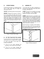
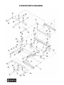
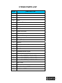
CT052N 12” DOVETAIL JIG User Manual TABLE OF CONTENTS General Safety Instructions------------------------------------------------------------------- 3 Features ------------------------------------------------------------------------------------------- 4 Un-packing---------------------------------------------------------------------------------------- 5 Assembly------------------------------------------------------------------------------------------ 5 Mounting ------------------------------------------------------------------------------------------ 5 Capacities----------------------------------------------------------------------------------------- 5 Preparation --------------------------------------------------------------------------------------- 6 Adjustment Controls---------------------------------------------------------------------------- 7 Clamping Adjustment -------------------------------------------------------------------------- 8 Side Stop Setup --------------------------------------------------------------------------------- 8 Template Adjustment -------------------------------------------------------------------------- 9 Fence Adjustment ----------------------------------------------------------------------------- 10 Operation ---------------------------------------------------------------------------------------- 11 Regular Use------------------------------------------------------------------------------------- 12 Rebetted Drawer Fronts --------------------------------------------------------------------- 13 Flush Offset Joint ------------------------------------------------------------------------------ 13 Rabbeted Joint --------------------------------------------------------------------------------- 13 Box Finger Joint-------------------------------------------------------------------------------- 13 Tear-Out ----------------------------------------------------------------------------------------- 14 Excessive Fit------------------------------------------------------------------------------------ 14 Incomplete Fit ---------------------------------------------------------------------------------- 14 Offset Edges ------------------------------------------------------------------------------------ 15 Fit Too Tight or Too Loose ------------------------------------------------------------------ 15 Uneven Fit --------------------------------------------------------------------------------------- 15 Parts Diagram ---------------------------------------------------------------------------------- 16 Parts List----------------------------------------------------------------------------------------- 17 Warranty----------------------------------------------------------------------------------------- 18 2 GENERAL SAFETY INSTRUCTIONS Extreme caution should be used when operating all power tools. Know your power tool, be familiar with its operation, read through the owner’s manual and practice safe usage procedures at all times. ALWAYS read and understand the user manual before operating the machine. DISCONNECT the power source when changing blade and / or making adjustments. CONNECT your machine ONLY to the matched and specific power source. NEVER leave a tool unattended while it is in operation. ALWAYS wear safety glasses respirators, hearing protection and safety shoes, when operating your machine. NEVER reach over the table when the tool is in operation. DO NOT wear loose clothing or jewelry when operating your machine. A SAFE ENVIRONMENT is important. Keep the area free of dust, dirt and other debris in the immediate vicinity of your machine. BE ALERT! DO NOT use prescription or other drugs that may affect your ability or judgment to safely use your machine. ALWAYS keep blades, knives and bits sharpened and properly aligned. ALL OPERATIONS MUST BE performed with the guards in place to ensure safety. ALWAYS use push sticks and feather boards to safely feed your work through the machine. ALWAYS make sure that any tools used for adjustments are removed before operating the machine. WARNING The safety instructions given above can not be complete because the environment in every shop is different. Always consider safety first as it applies to your individual working conditions. 3 CT052N - 12” DOVETAIL JIG FEATURES MODEL CT052N – 12” DOVETAIL JIG As part of the growing line of Craftex machineries, we are proud to offer the CT052N a 12” Dovetail Jig. By following the instructions and procedures laid out in this user manual, you will receive years of excellent service and satisfaction. The CT052N is a professional tool and like all power tools, proper care and safety procedures should be adhered to. OVERALL DIMENSIONS Height............................................................. 6” Width .............................................................. 17” Depth.............................................................. 12” Shipping Weight ............................................. 22” Net Weight ..................................................... 23 lbs. CAPACITY Material Thickness, sides ............................... 5/16” to 1-1/4” Material Thickness, front & back .................... 5/8” to 1-1/4” Maximum Width ............................................. 12” Joint................................................................ 5/8” with 1/2" Template CONSTRUCTION Jig .................................................................. Pre-Formed Steel Clamps ........................................................... Single Lever Adjustable Cam Template ........................................................ CNC Machined Aluminum ROUTER SPECIFICATIONS Maximum Router Base Size........................... 7” Router Bit Required........................................ 14°, 1/2” Dovetail with 1/4” Shank Guide Bushing Required ................................ 7/16” O.D 4 UNPACKING ASSEMBLY The machine is properly packaged in a carton for safe transportation. When unpacking, carefully inspect the carton and ensure that nothing has been damaged during transit. The jig is shipped fully assembled except for the two hand levers. Screw the threaded end of each hand lever into the clamping rods located on the top, and front of the dovetail. Tighten until secure. When all the items are removed from the package, you should have the following: 1. Dovetail Jig 2. Hand Lever 3. Hand Lever MOUNTING Place the jig on your bench top so the front lap rests against the front of the bench top. The jig has mounting holes on the front and rear. Locate the mounting holes and mark the locations with a pen. Drill the appropriate size holes and secure the jig to your bench using screws, nuts and bolts. IMPORTANT Figure-1 Inventory While doing the inventory if you can not find any part, check if the part is already installed on the dovetail jig. If you do not want to permanently secure the jig to your bench, mount the jig to a piece of 3/4" plywood that can be clamped to your bench top or clamp the jig to the front of your bench. CAPACITIES The CT052N is designed to produce halfblind dovetail joints with a router. 7/16" guide bushing, and 14°, 1/2" dovetail router bit. Half-blind dovetails are very strong and are commonly used in fine drawer construction. The term "half-blind" refers to the fact that the pins and tails can only be seen from the side. The CT052N is capable of processing material up to 1-1/4" thick and up to 12" wide. 5 It is designed to be used with 1/4" shank, 1/2", 14° dovetail bits only. The bit should protrude approximately 19/32”" below the base which is the thickness of the comb plus the depth of the pin. The maximum router base size that can be used with this jig is 7" in diameter. The guide bushing should protrude 1/8" to 3/16" from the base of the router and be 7/16" in outside diameter (0.0.). IMPORTANT This jig can only be used with a guide bushing attached to your router base and the guide bushing can be bought separately according to specific router. The table below shows the pin widths, produced by this jig's 1/2" template. Template Size Bit Size Bushing Size Pin Width 1/2" 1/2" 7/16" 9/16" PREPARATION It is important to plan your work before starting. If joining multiple pieces for a drawer or series of drawers, it is best to label the pieces as front, back and sides and which face will be inside or outside. It is also best to label the ends so it is clear which end mates with another. Labeling will save setup time and avoid costly mistakes in the long run. A typical drawer has a 3/4" thick front with sides made of 1/2" material. The dovetail jig's design requires that you use the same stock thickness for the back as you do for the front. Your drawer fronts and backs must be at east 5/8” thick to fully accommodate the length of the dovetails without compromising strength. After all the pieces have been cut to size and checked to ensure square- ness, set them on a bench in the order that they will be fitted together. Lay each piece down so the inside faces up. Label each piece on the inside. Figure-3 Pieces for labeling Figure-2 Thickness of the comb plus depth of the router is the total depth 6 ADJUSTMENT CONTROLS Hand Levers: Used to clamp the work-piece in place. The CT052N Dovetail Jig has been designed to accommodate various stock thicknesses and router base sizes. The jig can be used for production runs of similar parts after setup is completed. Fence Knobs: Loosen these knobs to adjust fence position. Router travel is stopped when the router base contacts the fence. Upper Side Stops: Align the work-piece horizontally under the template. NOTE When describing adjustments and operations in this manual, reference is made to the pieces being joined as fronts, backs, or sides. These pieces can be compared to drawer fronts, backs, and sides. Front and back pieces mount horizontally on top of the jig and side pieces mount vertically in the front of the jig. The insides of the boards always face out. Side Stops (front): Align the vertical workpiece to the horizontal work-piece. Template Height Lock Knobs: Loosen these knobs to adjust the template height. Template Lock Knob: Loosen these lock knobs to move the template to the front or rear. Clamping Pressure Knobs (Upper & Front): Control the height of the clamping bar and adjust cam clamping pressure. Figure-4 Adjustment controls 7 CLAMPING ADJUSTMENT TO ADJUST THE SIDE STOPS: The clamping pressure should be adjusted so the work-piece can be easily slid under the bar when the hand lever is up. Push the hand lever down to hold the work-piece in place. Do not use excessive force when pushing the lever. If excessive force is required, loosen the clamping pressure knobs slightly. 1. Start with the drawer back. It goes under the top clamp and the template. This piece lies horizontally. Move it near either one of the side stops. 2. Loosen the screws on the side stop and shift the work-piece so it is centered under the template fingers shown in Figure-6. When centering ensures that the pins and tails on the ends will be identical to each other. Clamp the back in place. Figure-5 Work-piece clamped SIDE STOP SET UP The side stops serve three purposes: 1. They position each work-piece square to each other. 2. They offset the two work pieces for proper alignment. 3. They give lateral support to the work pieces during router. Since tails and pins are routed in one operation. The work-pieces must be offset. The amount of offset is equal to the width of the template fingers. IMPORTANT pieces cut perfectly square for ToAll adjust themust side be stops: the jig to work properly. 8 Figure-6 Shows the location of the front side stop. Note how the board is centered under the template 3. Now, insert a drawer side under the front clamp. This piece will be vertical. 4. Adjust the height so the end of the vertical board overlaps the end of the horizontal board. It is not crucial that the pieces be flush, yet. 5. Clamp the side in place. 6. Release the horizontal piece and butt it against the side piece mounted in the front of the jig. Ensure that the horizontal piece remains centered under the template fingers. Re-clamp in place. 7. Loosen the two fence knobs and slide the fence all the way back so the upper side stop adjustment screws are accessible. 8. Loosen the upper side stop with a Phillips screwdriver and slide it next to the horizontal piece. Re-tighten the side stop screws. Do not over-tighten. The plastic will crack. 9. Release the side piece from the front of the jig and remove the front clamping system by unscrewing the clamping adjustment knobs. 10. Scribe a line exactly 1/2" from the edge of horizontal piece. Use the technique shown in Figure-7. HINT If you are not using the 1/2" template, scribe the line so the distance from the edge equals the width of the template fingers. 11. Loosen the front side stop screws and slide the front side stop against the square. Tighten the two Phillips screws. Be careful: over-tightening will crack the side stops. 12. Replace the front cam clamping system. IMPORTANT The dovetail jig is capable of processing two sets of joints at one time if the sum of the widths of both sets is less than 12". If you wish to make two sets of joints at one time, adjust both sets of side stops at each end of the jig. Refer to Steps 1 through 12 above. Figure-7 Shows scribing a line 1/2" from the edge of the horizontal piece TEMPLATE ADJUSTMENT The template is adjustable from front to back so that the joint will be hidden when the dovetails are complete. Adjustment is made by loosening the two lock knobs on the side and the two lock levers on the front of the jig. Don't adjust the screws holding the template. TO ADJUST THE TEMPLATE TO THE PROPER POSITION: 1. Mount your drawer pieces in the jig. The horizontal piece must be tight and flush with the top of the vertical piece. When mounted correctly, you'll be able to see the top edge of the vertical piece. 2. For pieces that are less than 7/8" thick, slide the template so the front edge of the template fingers are 1/8" back from the top edge of the vertical piece. See Figure8. For side pieces thicker than 7/8", add 1/8" to the amount that the board exceeds 7/8". Then, set the front edge of the template fingers back from the edge by that sum. See Figure-8. 9 Figure-8 Shows checking the template to make sure it is parallel to the top of the vertical pieces. The inside faces are showing. IMPORTANT Ensure that the front edge of the template is parallel to the edge of the vertical workpiece. To maintain a high degree of accuracy when adjusting the template, measure at one end of the jig then measure at the other end. Make adjustments to the template and remeasure both positions. To measure at both ends of the jig, try shifting the vertical piece to the other end of the jig or clamp two pieces at each end of the jig as shown in Figure-8. It is not necessary to simultaneously measure with two rulers. The two rulers only represent two measurement locations. 5. Tighten the two template lock knobs and recheck your measurements. Figure-9 Shows the template set back an additional 1/8” for a 1” thick board. The inside faces are showing FENCE ADJUSTMENT The fence controls the depth of the dovetail pins by limiting the distance that the router travels. The router stops when the router base hits the fence. The fence must be adjusted parallel to the edge of the vertical piece just like the template. TO ADJUST THE FENCE: 1. Mount a 7/16" 0.0 guide bushing in your router base. Measure the amount that the template overlaps the vertical piece. Multiply that number by two. For example, if the template is offset from the edge of the vertical piece by 1/8" and thickness of the side piece is 1 /2", then the overlap is 3/8". So, 3/8" x 2 is 3/4". 2. Now, add 1/32" to the distance you calculated in step 1. Measure the distance from the edge of the router base to the edge of the guide bushing and add it to the distance you calculated in step 2. 10 The distance calculated in step 3 is the distance that the fence should be back from the template. Loosen the two fence lock knobs and slide the fence into position. Ensure that the fence is parallel to the front of the template and tighten the two lock knobs. NOTE The procedure above is not affected by changing the router bit vertical depth of cut. When you've finished with all the calculations, make a test run using some scrap wood to check your positioning. Fine tune if necessary. HINT When you have come up with a reliable number (E) for your router, base, bushing, and wood thickness combination, record it here and keep it for future reference. (E) will be different for different thickness of wood. 11 OPERATION Your router base must accept a guide bushing with a 7/16” outside diameter and an inside diameter large enough to accept a 1/4” shank dovetail bit. Securely mount the guide bushing to your router. Refer to your router’s operating manual for further instructions. Choose a 1/2” dovetail router bit with a 1/4" shank. Ensure that the router is unplugged and securely mount the bit in the router collet. Set the router bit to extended 23/32” below the base plate of the router. Before cutting tails and pins in a finish piece, it is important to test your adjustments with sample pieces to judge the quality of the joint. It may be necessary to make additional adjustments to the dovetail jig to improve the fit. With the jig completely adjusted, you should be ready to test it out. Review all safety rules if you are unsure abut the risks associated with operating a router in conjunction with this jig. A. REGULAR USE 1. Start with joint 1 that you set up in Section 7. 2. Position the mated pieces in the jig so the insides face out and up. Each piece must be tight against the side stops. The back pieces are positioned horizontally on top of the jig. The mating side pieces are positioned vertically in the front of the jig. The end of the pieces must be flush with the top face of the back piece. See Figure-10. Figure-10 Shows the dovetail jig set up for use 5. The router base and bit must be secure before plugging in your router. Hold the router firmly with both hands and support it on the template. Make sure that the bit is clear of the work-piece. Turn the router on and gently ease the bit into the work, letting the guide bushing gently contact the template. Facing the dovetail jig, start at your left side and work to the right, first remove the material IN FRONT of the fingers. Second, remove the material between the fingers. Ensure that the router base and guide bushing stay in firm contact with the template. HINT If you are using material thicker that 7/8", cut it in two stages. First, remove the material in front of the fingers. Second, remove the material between the fingers IMPORTANT Be careful when the router bit exits the work-piece to reduce the risk of tear-out. 5. Remove both pieces from the jig and join the dovetails. 12 5. It may be necessary to tap the two pieces together with a hammer and wood block. If alignment is so poor that the two pieces will not fit together, line up each piece as much as possible and determine the direction and degree of fine adjustment. If the two pieces do not fit, it is usually because they were not milled square or the pieces were not flush with each other in the jig. 2. The fence must also be set back an additional amount equal to the width of the rabbet. C. FLUSH OFFSET JOINT D. RABBETED JOINT Figure-11 Shows a finished drawer and 2 sides ready to be joined E. BOX FINGER JOINT B. RABBETED DRAWER FRONTS Drawer fronts that have been rabbeted around the inside edge to create a lip to restrict drawer travel in the closed position require some additional setup. To produce half-blind dovetails on rabbeted drawer fronts: 1. A spacer must be added to the vertical side stop in the front of the jig to compensate for the rabbet. The width of the spacer must be the same width as the rabbet. When cutting the box finger joint, both pieces of stock must be put into the dovetail machine vertically as in Figure-6. One piece of stock is lined up flush to the left of one of the comb table fingers and the other piece of stock is lined up flush to the right of one of the comb table fingers. 13 Always set router bit depth to cut the exact thickness of the stock being used, this will give you a perfect box finger joint every time. To avoid router bit from hitting template, raise up comb table to the appropriate height with shim stock. C. INCOMPLETE FIT An incomplete fit occurs when the side piece protrudes from the end of the front or back piece. See Figure -13. CAUSE: The distance between the edge of the side piece and fence is set too narrow. A. TEAR-OUT When cutting across the grain of the wood, tear-out or splintering may occur when the router bit exits the work-piece. To prevent tear-out, you may scribe a line on the side piece with a sharp knife or awl at the same distance down that router bit will cut. Tear out can be eliminated or reduced by backing up the work-piece with a scrap piece or simply using extra care when operating the router. B. EXCESSIVE FIT If the tails on the side piece fit too deeply in the pins on the front or back piece, the depth of cut is too deep. See Figure-13. CAUSE: The distance between the edge of the side piece and fence is set too wide. REMEDY: Adjust the fence forward by the same amount that the pins are exposed. Refer to the procedure described above for fence adjustment. REMEDY: Adjust the fence toward the back of the jig by the same amount that the tails protrude out. TO ADJUST THE FENCE: 1. Made a reference line indicating the current position of the fence either on a piece of masking tape located on the jig or on the sample piece clamped under the fence. 2. Measure the distance that the tails protrude. 3. Loosen the fence locking knobs and slide the fence toward the back of the jig by the same distance. 4. Ensure that the fence is parallel to the edge of the work-piece and tighten the lock knobs. Figure-13 shows incomplete fit Figure-12 shows excessive fit 14 D. OFFSET EDGES E. UNEVEN FIT If the side piece edge is not aligned with the front or back piece edge, the edges are offset. See Figure-14. If the side piece fits either excessively or protrudes at on edge and not the other, the fit is uneven. See Figure-15. CAUSE: The side stops are not set correctly. CAUSE: The fence is not parallel to the edge of the work-piece or the template is not parallel to the edge of the work-piece. REMEDY: Measure the amount of offset on the two test pieces and adjust the front side stop accordingly. The front side stop must be offset from the top side stop by the exact width of the fingers on the template you are using. Ensure that the front side stop remains square to the work-piece mounted on top of the jig. REMEDY: Adjust the fence or template in the desired direction until it is parallel to the edge of the work-piece. For the highest degree of accuracy, clamp the two work-pieces in the front of the jig so they are positioned against the two side stops and measure the distance between the edge of the work-piece and the edge of the fence or template. Adjust the fence or template so the measurement on the other end of the jig equals the first. Recheck the first measurement in case it changed during adjustment. Figure-14 shows offset edges D. FIT TOO TIGHT OR TOO LOOSE If you find the fit to be about right in every other aspect, but it is simply a little too tight or too loose, the depth of the router bit is probably maladjusted. Figure-15 Shows uneven fit 1. If the fit is too tight, decrease the protrusion of the router bit from the base. 2. If the fit is too loose, increase the protrusion of the router bit from the base. 15 CT052N PARTS DIAGRAM 16 CT052N PARTS LIST INDEX DESCRIPTION 01 1/2" Aluminum Template 02 Bracket 03 Bracket 04 Knob 05 Eccentric Wheel 06 Handle 07 Spring 08 Knob 09 Fence Lock Knob 10 Fence 11 Threaded Bushing 12 Jig Base 13 Stops (Short) 14 Support 15 Flat Washer 8mm x 15mm x 1t 16 Lock Knob 17 Slide Bar 18 Threaded Bracket (Right) 19 Threaded Bracket (Left) 20 Screw - Pan HD Philips 10-24 x 3/8" 21 Screw - Flat HD Philips 10-24 x 5/8" 22 Screw - Flat HD Philips 1/4"-20 x 3/8" 23 Stop (Long) 24 Rod 25 Thumb Lock Lever 5/16" 26 Flat Washer 5/16" 17 WARRANTY CRAFTEX 2 YEARS LIMITED WARRANTY Craftex warrants every product to be free from defects in materials and agrees to correct such defects where applicable. This warranty covers two years for parts and 90 days for labour (unless specified otherwise), to the original purchaser from the date of purchase but does not apply to malfunctions arising directly or indirectly from misuse, abuse, improper installation or assembly, negligence, accidents, repairs or alterations or lack of maintenance. Proof of purchase is necessary. All warranty claims are subject to inspection of such products or part thereof and Craftex reserves the right to inspect any returned item before a refund or replacement may be issued. This warranty shall not apply to consumable products such as blades, bits, belts, cutters, chisels, punches etceteras. Craftex shall in no event be liable for injuries, accidental or otherwise, death to persons or damage to property or for incidental contingent, special or consequential damages arising from the use of our products. RETURNS, REPAIRS AND REPLACEMENTS To return, repair, or replace a Craftex product, you must visit the appropriate Busy Bee Tools showroom or call 1800-461-BUSY. Craftex is a brand of equipment that is exclusive to Busy Bee Tools. For replacement parts directly from Busy Bee Tools, for this machine, please call 1-800-461-BUSY (2879), and have your credit card and part number handy. 18 All returned merchandise will be subject to a minimum charge of 15% for re-stocking and handling with the following qualifications. Returns must be pre-authorized by us in writing. We do not accept collect shipments. Items returned for warranty purposes must be insured and shipped pre-paid to the nearest warehouse Returns must be accompanied with a copy of your original invoice as proof of purchase. Returns must be in an un-used condition and shipped in their original packaging a letter explaining your reason for the return. Incurred shipping and handling charges are not refundable. Busy Bee will repair or replace the item at our discretion and subject to our inspection. Repaired or replaced items will be returned to you pre-paid by our choice of carriers. Busy Bee reserves the right to refuse reimbursement or repairs or replacement if a third party without our prior authorization has carried out repairs to the item. Repairs made by Busy Bee are warranted for 30 days on parts and labour. Any unforeseen repair charges will be reported to you for acceptance prior to making the repairs. The Busy Bee Parts & Service Departments are fully equipped to do repairs on all products purchased from us with the exception of some products that require the return to their authorized repair depots. A Busy Bee representative will provide you with the necessary information to have this done. For faster service it is advisable to contact the nearest Busy Bee location for parts availability prior to bringing your product in for repairs.