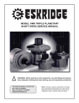
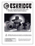
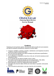
1
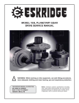
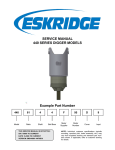
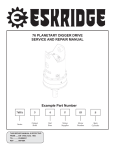
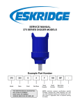
65E PLANETARY GEAR DRIVE
SERVICE AND REPAIR MANUAL
!
WARNING: While working on this equipment, use safe lifting procedures, wear adequate clothing and wear hearing, eye and respiratory protection.
This service manual is effective
From:...... S/N 55013, june 2002
To:............ CURRENT
Ref:......... SM65ED2-Ad
65E Single Stage Exploded View Drawing
65E Double Stage Exploded View Drawing
Lubrication & Maintenance
Using the chart below, determine an appropriate lubricant viscosity. Use only EP (extreme pressure) or API GL-5 designated lubricants.
Change the lubricant after the first 50 hours of operation and at 500 hour intervals thereafter. The gear drive should be partially disassembled to inspect gears and bearings at 1000 hour intervals.
Recommended ambient and operating temperatures for conventional and
synthetic gear lubricants
-50
-25
0
25
50
75
100
125
150
175
200
225
250 F
107
121 C
80W90 conventional
75W90 conventional
85W140 conventional
Min Ambient/operating temp
Max Operating temp
Max Ambient temp
75W90 synthetic
80W140 synthetic
-45
-32
-18
-4
10
24
38
52
66
79
93
Note: Ambient temperature is the air temperature measured in the immediate vicintiy of the gearbox. A Gearbox exposed to the direct rays of
the sun or other radiant heat sources will operate at higher temperatures and therefore must be given special consideration. The max operating
temp must not be exceeded under any circumstances, regardless of ambient temperature.
If your unit was specified “shaft up” or with a “-Z” option, a grease zerk was provided in the base housing. For shaft-up operation, the
output bearing will not run in oil and must be grease lubricated. Use a lithium based or general purpose bearing grease sparingly every
50 operating hours or at regular maintenance intervals. Over-greasing the output bearing should be avoided as it tends to fill the housing
with grease and thicken the oil
ESKRIDGE MODEL 65E OIL CAPACITIES
Operating Position
Oil Capacity
Oil Level
Single stage
Double stage
Horizontal Shaft
2.25 pints / 1.1 liters
2.25 pints / 1.1 liters
To horizontal centerline of
gear drive
Vertical Shaft (Pinion Up)
2.5 pints / 1.2 liters
2.5 pints / 1.2 liters
To side port on gear drive
base
Vertical Shaft (Pinion Down)
2.5 pints / 1.2 liters
2.5 pints / 1.2 liters
To midway on upper/
primary gear set
ESKRIDGE PART NUMBER INTERPRETATION
Note: All non custom Eskridge Geardrives are issued a descriptive part number which includes information regarding the Model, means of shaft retention, base style, shaft style, input mounting, input shaft size, overall ratio and
various available options. For a detailed breakdown of this information, please refer to Eskridge product specification sheets found at: http://www.eskridgeinc.com/geardrives/gearprodspecs.html
Unit Disassembly Procedure
1)
1) Scribe a diagonal line across the outside of the unit from cover
(6) to case (1) before disassembly to assure proper positioning of pieces during reassembly.
Rotate the planet gears (10) to check for abnormal noise
or roughness in bearings (18) or planet shafts (8). If further
inspection or replacement is required, proceed as follows.
2) Drive roll pins (29) into planet shafts (8).
3) Press or drive planet shafts out of carrier (3).
4) Slide planet gears (10) along with planet washers (15) out of
primary carrier (3).
5) If planet bearings (18) must be replaced, they may now be
removed from primary planet gears (10).
6) Use 1/8 inch pin punch to remove roll pins (27) from planet
shafts.
7) Rebuild primary planet carrier assembly in reverse order using any needed new parts. Planet shafts (8) should be installed with chamfered end of 1/8 inch hole toward outside
diameter of carrier. This will aid in alignment of holes while
inserting roll pins.
2) Remove magnetic pipe plug (32) and drain oil from unit. Maximum drainage occurs when oil is warm.
3) Remove eight cover bolts (24) and lockwashers (27).
4) Lift off cover (6). The input shaft(12) and carrier thrust washer
(17) may be lifted out of carrier assembly.
5) Lift primary planet carrier assembly (3,8,10,15,18, & 29) out of
case.
6) The output shaft (13) and secondary planet carrier assembly
may now be removed as follows:
a)
The secondary planet carrier (2) spline is a press fit
onto output shaft (13) spline. Case (1) should be set on
a plate or table with output shaft protruding downward
through hole in table.
Secondary Planet Carrier Subassembly (Items 2, 5, 7, 9, 14, 15, 19, 22 & 28)
b) Loosen but do not remove shaft retaining cap screws
(25).
NOTE: Care should be taken not to damage output shaft or
injure your feet when shaft falls out of case.
c) Press output shaft out bottom of case by applying press
load to top end of capscrews (25). Remove capscrews
to allow shaft to pass through case.
d) Remove shim(s) (14) from top end of shaft (13).
7)
Secondary planet carrier assembly (2,5,7,9,15,19, 22 & 28)
may now be lifted out of case.
Output Shaft Subassembly
(Items 13, 20, 31)
1) Outer tapered bearing cone (20) may be removed using a
gear puller. If reusing old bearing cone, do not damage roller
cage by pulling on it.
2) To replace shaft seal (31) lubricate inner lip of new seal and
turn so that open side is facing upward. Slide seal down output shaft (13) all the way to gear teeth or until it fits snug over
seal diameter.
1)
Disassembly procedure is the same as previous section on
primary planet carrier subassembly (steps 1-4) except substitute these parts: secondary carrier (2), secondary planet
gears (9), planet bearings (19), secondary planet shafts (7)
and roll pins (28).
Reassembly
Primary Planet Carrier Subassembly (Items 3, 8, 10, 11, 15, 18 & 29)
1) Place carrier (2) with hub down as shown above. Place bearing retainer plate (5) in bottom of carrier. Insert secondary
planet gears (9).
2) Turn carrier (2) over while using the planet gears (9) to hold
retainer plate (5) in place.
3) Remove one planet gear (9) and insert a bearing (19). Install two washers (15) (one on either side of the planet gear).
Place in carrier and install planet shaft (7) and roll pin (26).
Repeat for two remaining gears.
NOTE: Press bearing onto hub by pressing on inner race
only. DON’T press on roller cage or it may damage bearing.
4) If tapered inner bearing cone (22) on hub of secondary carrier
(2) must be replaced, it may be removed using a gear puller.
Then, press a new bearing cone onto hub making sure bearing shoulder is tight against hub shoulder.
Case Subassembly
1) Inspect inner and outer bearing cups (21 & 23) and replace if
necessary.
2) Clean all foreign material from magnetic drain and fill plug
(32).
planet gears (9).
NOTE: It is important that the holes in the retainer plate remain centered between planet gears. A certain amount of tool
clearance will be necessary in order to install and torque the
capscrews (25).
8)
Unit Reassembly
Bearing Pre-Load Measurement and Setting:
carrier assembly down until carrier spline touches output
shaft (13) spline. Rotate carrier by hand until you are certain carrier spline has started cleanly and squarely onto shaft
spline. View down through top of secondary carrier assembly
through counter-bored holes in retainer plate (5). If needed,
align holes in retainer plate directly over holes in the shaft
and shim(s) (14).
DIM "A"
DIM "B"
9) 1)
2)
3)
Install the secondary carrier assembly with the bearing (22)
installed, into the base (1) with cups (21 & 23) installed. Turn
this assembly upside down (outer bearing pointing up). Support the retainer plate (5) on a suitable support so the entire
assembly is free to rotate on the inner bearing on the support.
See the illustration above. Place the outer cone (20) into the
outer cup (21) and carefully spin this assembly 1-3 revolutions to allow the bearings to seat. Using a depth micrometer,
measure down from the outer bearing cone mounting surface
to the bottom surface of the retainer plate (5). Record this
measurement as A. Next, measure from the inner end of
the shaft (13), where the three threaded holes are located, to
the bearing seat. Record this measurement as B. Subtract
A-B. This number is the un-preloaded gap in the bearing
stack. The correct amount of pre-load is generally between
0.005 inch and 0.020 inch compression of the bearings. Add
or remove shims to achieve the desired gap which will compress or pre-load the beairngs. Each shim is 0.005 inch
thick. The lower gap will produce rolling torque of 50-150
in-lb, the higher gap will produce rolling torques of 150-250
in-lb. Fewer shims = tigheter bearing pre-load, more shims =
looser bearing pre-load.
10) Tighten the socket-head capscrews (25) to a torque of 90 ftlb. Spin the gearbox case (1) on the shaft 2 to 3 revolutions.
Now re-tighten the capscrews (25) to a torque of 90 ft-lb. This
step allows the bearings to seat into their running position
and ensures the correct torque on the fasteners.
11) Place secondary thrust washer (4) onto center of secondary
planet carrier assembly.
12) Install sun gear (11) into center of secondary planet carrier.
13) To install primary planet carrier assembly hold inside diameter of carrier (3) and rotate until planet gears line up with case
gear teeth and sun gear. Assembly will drop into place.
NOTE: A simple planetary such as this does not require a gear
timing procedure.
14) Insert input gear (12) into unit so that teeth mesh with primary
planet gears (10).
15) Place input thrust washer (17) over input gear.
16) Place a new o-ring (30) on bottom of cover (6).
Place the shaft seal (31) onto the seal-diameter of the shaft
(13). Press the outer bearing cone (20) onto the shaft; press
only on the race, not on the cage.
17) Set cover (6) on top of unit and refer to scribed line for proper
orientation. Install and torque eight cover bolts (24) with lockwashers (27) to 32 ft-lbs.
Turn case pinion side up. Apply a layer of lithium grease to
outer bearing cup (21). Place the shaft (13) into case (1) so
that the shaft’s outer tapered bearing cone (20) is seated in
case’s outer bearing cup (21). Tap shaft seal (31) into place.
17) Check to be sure magnetic plug (32) is securely installed into
side of case (1).
18) Add gear oil as specified on page 2. Correct oil level will
measure to middle of primary planet gears (10) when in the
vertical operating position.
Turn case pinion side down.
19) Put pipe sealant on magnetic plug (32) and install into oil fill
hole in cover (6).
5) Apply a layer of lithium grease to inner bearing cup (23).
6)
Install the correct number of shims (14), determined in step
1 onto the end of the shaft (13) with the holes lined up correctly.
7) Rotate bearing retainer plate (5) inside secondary carrier assembly so that counter-bored holes are centered between
Counter-bored holes should be centered between planet
gears (9). Slowly press secondary carrier assembly down
tightly against output shaft (13).
NOTE 1: Rolling torque at proper bearing preload will vary according to the application. At output speeds of greater than 25
RPM, preload torque (including seal drag) should be in the range
of 50 to 150 in-lbs. At less than 25 RPM, rolling torque should be
150 to 250 in-lbs.
CAUTION: Shaft is not retained at this time.
4)
Install secondary carrier assembly (2) into case (1) as follows: Rotate secondary carrier assembly back and forth until
planet gear teeth (9) mesh with gear teeth in case (1). Let
20) Insert a shaft, such as an output shaft from a hydraulic motor,
into input gear (12) and rotate by hand to be sure unit turns
smoothly and easily.
THE GEARBOX IS NOW READY FOR USE.