1
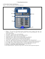
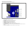
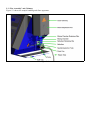
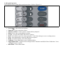
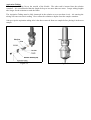
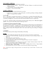
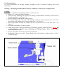
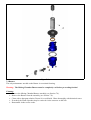
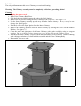
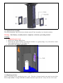
Model BWB-1 Performance Plus Flame Photometer Operator Manual Copyright 2008, BWB Technologies UK, Ltd. All rights reserved 1. Intended Use This Operator’s Manual contains complete instructions for setting up, using and maintenance of the Model BWB-1. Service information for use by qualified personnel is available in the separate Service Manual. The Model BWB-1 is intended for use by persons knowledgeable in safe laboratory practices. If the instrument is not used in accordance with these instructions, the protection provided by the equipment may be impaired. The information contained in this document was correct at the time of publishing. However, BWB Technologies UK, Ltd reserves the right to change specifications, equipment, and procedures at any time, without notice. To obtain a current version go to www.bwbtech.com. 2. Introduction 2.1 Introduction The BWB-1 Performance Plus is a multi-channel, low temperature Flame Photometer for the simultaneous measurement of Na, K, Li, Ca, and Ba in a variety of samples. It is designed for ease of use and reliable, trouble-free operation. With built-in air compressor, diagnostic indications, computer interface and control, automatic gas shut off, choice of Single Point or Multi-Point calibration and internal data handling the BWB-1 provides a simple, yet fully capable, instrument for the modern laboratory. 2.2 Summary of the Instrument The BWB-1 employs a low temperature flame using air and propane, butane, or a combination of the two (as in LPG). Interference type filters are provided for Na, K, Li, Ca, and Ba. All these ions are monitored continuously and results shown on the digital display. There are dual computer access points provided (RS232 and USB) that allow for interfacing to external software. Diagnostic indications of several parameters are displayed on the front panel. Safety cut off of the gas supply is provided through constant monitoring of the flame. If the flame should go out for any reason, the gas will automatically stop flowing with a correspondent light on the panel and an audible signal alerting the user. The BWB-1 employs microprocessor technology to generate and store calibration curves eliminating the need to manually graph and calculate the results. Calibrations of each element can be done in either of two modes. In Single Point Mode a Blank solution and one Standard are used when the samples lie within the linear range. For samples that are higher in concentration the Multi-Point Mode uses a Blank and up to 15 Standard solutions to effect the curve. Embedded in the instrument enclosure is a built-in air compressor. A unique electronic control system automatically regulates the air pressure/flow to the optimum levels. No user adjustments are possible, or necessary, to achieve maximum performance. Provision for an external source of compressed air is included. Also, included as standard with the BWB-1, is a Starter Pack. It comprises Standard solutions, volumetric ware, sample cups, and replacement parts. Everything needed to begin immediate testing. 2.3 Reagents Provided with the BWB-1 are Standard solutions and Diluent Concentrate reagents. Samples and Standards must be diluted with the same batch of diluent, made up of 1 part Diluent Concentrate to 999 parts deionised or good quality distilled water. The same batch of diluent should be used as Blank and to prepare dilutions of standards and samples to prevent variations in water purity affecting the measurements. Great care should be taken so that contamination does not occur when preparing the samples and standards. Remember, the accuracy of the instrument is dependant on the accuracy and purity of the standards used for calibration. All solutions should be stored out of direct sunlight, in a cool place, and in airtight containers. Glass should not be used, as it will affect the Na concentration levels. Prolonged exposure to the atmosphere must be avoided to prevent evaporation. No further purification is required for Standard Solution Concentrates. 3. Unpacking the Instrument • • • Unpack the instrument and accessories. Note: The instrument weighs ~ 15 kg, follow safe lifting practices. Check all items for damage. Check that all items on the accessory list have been delivered. If any problems are encountered, contact your local distributor. Accessory List • • • • • • • • • • • • • Operating manual “Guide to Flame Photometry” Sodium Standard, 10,000mg/l, 150ml Potassium Standard, 10,000mg/l, 150ml Lithium Standard, 10,000mg/l, 150ml Calcium Standard, 10,000mg/l, 150ml Barium Standard, 10,000mg/l, 150ml Diluent Concentrate, 500ml Pipets, 1ml, 25 each Pipets, 10ml, 25 each Volumetric flask, 100ml, 3 each Sample cups, 20ml, 100 each Fuse, power supply, 2 each • • • • • • • • • • • • • Aspiration tubing and cleanout wire Waste drain tubing Replacement “U” Tube Power cords Gas hose clamp Gas hose. CD-ROM with data logging software. Deionised water 1000ml. Drip tray. Warranty statement. Registration form. Decon 90 2% Solution 1000ml. Safety data sheets. 4. Installation 4.1 Providing Power An AC supply of 100V to 250V, at 50 or 60Hz, is required for the BWB-1. The power supply automatically detects the mains voltage and provides the proper power to the various components of the instrument. Attach the proper power plug lead appropriate to the mains supply. Plug the power cord into the power receptacle on the rear panel. Plug the power cord into the mains source. 4.2 Providing Fuel A gas fuel supply of propane, butane, or propane/butane mixture (as in LPG) is used on the BWB-1. It should be regulated at the source to no more than 20Bar with a flow rate at least 0.4 l/min. The use of industrial quality gas is not recommended as impurities can enter, leaving deposits of dirt and oil, which will render the instrument inoperable. Note: For best results when measuring Barium it is recommended that Butane be used. Warning: Use of fuel gases other than propane/butane can result in a dangerous situation and cause severe damage to the instrument, which will void the warranty. Note: The securing of gas cylinders should conform to national and local regulations. Attach a good quality, high-pressure hose between the gas source and the gas regulator on the rear panel using the clamp provided to ensure a good seal. Warning: Test all gas hose connections for leakage with a soap solution, looking for bubbles when the gas source is opened. Leakage can result in a dangerous situation! If any odour of gas is detected or leakage discovered, STOP IMMEDIATELY and correct the situation. 4.3 Providing Waste Drain A sink or suitable container should be sited near the instrument to dispose of the waste overflow from the Drain Cup. If a waste container is used it should be situated so that its’ sides are below the bottom of the Drain Cup. Attach the supplied silicone tubing to the bottom port of the Drain Cup and route the other end to the sink or waste container. See Figure 5.3. 4.4 Site Conditions Warning: Under no conditions should the instrument be installed beneath overhanging cabinets! There must be at least 1 meter of clear space above the Chimney. For optimum performance, the instrument should be installed according to the following conditions. • The environment must be clean and free of dust and airborne contaminants. • The instrument must be placed on a sturdy worktop. The BWB-1 requires about 50cm deep by 60cm wide by 151cm high of bench space. • Avoid sites that expose the instrument to direct sunlight or draughts. • To meet the specification the ambient temperature must be within the range +10°C to +35°C and a maximum relative humidity of 85%, non-condensing. 4.5 Alternate Air Source If an exterior alternate air source is desired, there is a hose barb on the rear panel. See Figure 5.2 The air source must be regulated to 0.20- 0.34 bar and be free of oil, dust and airborne contaminates. Do not use oxygen or oxygen-enriched air! . 4.6 Installing Chart Recorder The chart recorder jacks are located on the rear panel (red+, black-). See Figure 5.2. 4.7 Installing Computer Cord The serial ports for connecting to a computer are located on the rear panel. See Figure 5.2. 5. Operating Instructions 5.1 Front Panel Controls and Indicators Figure 5.1 shows the front panel controls and indications. Figure 5.1 1. Display: The four-line LCD display presents information, menus, prompts, data entry, and resultant test values. All parts of the menu structure can be accessed through the “Up” and “Down” scroll buttons. 2. “Read LED”: Indicates when in the Read Mode. 3. “Cal LED”: Indicates when in any of the Calibration Modes. 4. “Dual Mode LED”: Indicates when in the Dual Mode. 5. “Single Point” LED: Indicates when in doing a Single Point calibration. 6. “Multi Point LED”: Indicates when doing a Multi Point calibration. 7. “U Tube LED”: Indicates when the “U” tube is not filled properly. 8. “Wait LED”: Indicates that the instrument is warming up and is not ready to be used. 9. “Flame Out LED”: Indicates that the flame has extinguished. Also, an audible alarm will sound. 10. “Over Range LED”: Indicates that the sample is too high a concentration for the instrument. 11. “Error LED”: Indicates that something is amiss. Also, an audible alarm will sound. 12. “Na, K, Li, Ca, Ba LEDs”: Indicate which element is being calibrated. 13. “Key Pad”: Executes menu choices and enters data. 14. Fuel Adjustment Knob: Adjusts the air/gas ratio to control the flame height and temperature. 5.2 Rear Panel Controls and Connectors Figure 5.2 shows the rear panel controls and connectors. Figure 5.2 1. 2. 3. 4. 5. 6. 7. 8. Power Switch: Turns the power On/Off. Power Jack: Receives the power cord from the mains. Fuse Holder: Provides access to replace the fuse. Serial Port: RS232 or USB computer interconnect. Chart Recorder Output: Red (+) and Black (-). Cooling Fan: Maintains temperature inside enclosure. Fuel Gas Regulator: For Propane, Butane, or Propane/Butane mixture. Air Compressor Switch: Used to turn off the internal compressor when Alternate Air source is desired. 9. Alternate Air Hose Barb: Used when Alternate Air source is desired. 5.3 “Wet Assembly” and Chimney Figure 5.3 shows the sample handling and flame apparatus. Figure 5.3 5.4 Keypad Operation The keypad executes menu choices and enters data. Refer to Figure 5.4. • • • • • • • • • • • Figure 5.4 Scroll (↑ ↓). Moves between options. Numerals. Used to enter data values. Element symbols. Used to choose element when prompted. Blank. Press when running Blank solution. Accept. Accepts data entries and chooses options. Back. Goes back to previous menu operation. Used when missteps occur or exiting menus. Stop. From Main Menu, starts the Shut Down sequence. Read. From Main Menu, enters Read Mode. Calibrate. From Main Menu, enters Calibrate Mode. Single/Multi Point. Toggles between Single Point Calibration and Multi Point Calibration. Press “Accept” button to choose. Dual Mode. Enters Dual Mode. 5.5 Menu Structure Welcome Menu Upon initial power up, the instrument displays the Welcome Menu. There are three options in the Welcome Menu. 1 Turn on Flame 2 Maintenance Menu 3 Setup Turn on Flame is the default option. To choose, press the “Accept” button. The instrument will enter the Start Up routine (see below). To reach the Maintenance Menu, scroll to it and press the “Accept” button or press “2”. The Maintenance Menu has two options, which are discussed in the Maintenance Section. Press the “Back” button to return to the Welcome Menu. Setup is reached by scrolling to it and pressing the “Accept” button or pressing “2”. The Setup menu can also be reached from the Main Menu and is discussed below. Again, press the “Back” button to return to the Welcome Menu. Main Menu After the Start Up routine has finished, and the instrument is ready to be used, it enters the Main Menu. The Main Menu consists of the following. 1 Read Ion Levels 2 Calibrate Options 3 Setup 4 Turn off Flame The “Up” and “Down” scroll buttons can be used to highlight each option, or simply select the option using the number. Pressing the “Accept” button will choose that option. Read Ion Levels Mode and Calibrate Options Mode can also be chosen with their shortcut buttons on the keypad. There are various sub-menus that are discussed under their respective sections. At any time, pressing the “Back” button will revert to the previous menu item. When in the Main Menu, pressing the “STOP” button will activate the Shut Down procedure. 5.6 Prompts The display will prompt the operator during many of the procedures. At any time an error is made, press the “Back” button to return to the previous step. 5.7 Start Up When the power switch is turned ON the BWB-1 displays the Welcome Menu. Turn on Flame is the default option and pressing “Accept” will begin the Start Up routine. Fuel Gas Preset For proper ignition, the fuel gas/air mixture needs to be pre-set close to the final setting. Turn the Fuel Adjustment Knob on the front panel to the right. Do not over tighten; damage to the valve could result. Turn the knob to the left 3-5 turns. Warning: Before attempting to start up the instrument make sure all the Installation instructions, including Warnings and Cautions, have been followed. Note: If Alternate Air source is desired, turn off the air internal compressor on the rear panel and apply the Alternate Air before turning the power to On. (See Section 4.5.) The following sequence and actions occur during Start Up. • Air compressor turns on. • Self-diagnostics initiate. If any problems are detected, the “Error LED” illuminates. • The Drain Cup sensor is monitored to ensure the “U” tube is properly filled. If not, the “U Tube LED” illuminates and the start sequence is halted. • The fuel gas shut off valve is opened to start the flow of gas. • The ignition circuit is activated to provide a spark at the burner. If the burner does not light within 10 seconds, the start routine is halted, the gas shut off valve ceases the gas flow, and the “Error LED” illuminates. • With successful ignition, the “Wait LED” illuminates and the instrument monitors itself until it reaches thermal stability. Warning: At this point in the Start Up procedure, open the Flame Inspection Port and make sure the flame has indeed ignited. If not, turn off the power immediately! Sometimes, especially when a fresh supply of gas is connected or the instrument has not been in use for an extended time, it will take time for the gas to fully pervade the gas system and a flame will not ignite or not continue to stay lit. Repeat the Start Up procedure three or four times, which should allow enough time for the gas to fill the system. Warning: If the Start Up routine was halted due to lack of flame ignition (even after trying a few times) make sure all gas connections are proper and no leakage is occurring before attempting to re-start. Flame Adjustment While viewing the flame through the Inspection Port adjust the gas flow with the Fuel Adjustment Knob on the front panel. The proper height of the flame is achieved when the small inner cones of the flame are 8-10 mm high. There is a flame adjust utility in the calibrate menu that shows the reading of Li as a bar graph to make adjustment easier. If the gas flow is too low the flame will start but will “lift off” the burner and the flame will go out. It is recommended to start off with a larger flame and reduce it once the flame has stabilised. In the case that the start sequence was halted due to improper “U” tube filling, turn the power switch to OFF, fill the “U” tube with tap water, turn the power switch to On, and press “Accept” to re-enter the start routine. Set-up The Set Up menu, available from both the Welcome menu and also the Main menu, allows you to set the units that you wish to measure in. You can choose ppm, mg/l or meq/l. Any subsequent measurements will be given in the unit chosen. 5.8 Aspiration Sample and standard solutions are introduced to the flame by the Nebuliser. This need to be kept clean and free of particulates. (See Maintenance Section, 7.5 and 7.6.) Nebuliser The Nebuliser can be removed from the Mixing Chamber by unscrewing the Retaining Clip and pulling it out. Never remove the Nebuliser while the flame is lit. Always shut the instrument down. See Figure 5.5. Needle The Needle is part of the preset nebuliser assembly. The needle must be kept clean and free from contamination. The setting of the needle within the nebuliser must NOT be adjusted. Aspiration Tubing The Aspiration Tubing fits on the outside of the Needle. The other end is inserted into the solution container. It is recommended that the length be kept to no more than one meter. Longer tubing lengths take longer for the solution to reach the flame. The Aspiration Tubing must be fully immersed in the solution so as to not draw in air. Air entering the tubing will cause an erratic reading. Never allow the solution to deplete from the sample container. Always wipe the aspiration tubing after it has been removed from one sample before placing it in the next sample. Figure 5.5 Figure 5.6 5.9 Calibration Calibration is the heart of accuracy in measurements. The BWB-1 provides two types of calibration, Single Point and Multi Point, depending on the concentration range (see Section 6.2). Single Point • Press “Calibrate” or scroll to Calibrate and press “Accept”. The display prompts “Choose Ion”. • Choose the desired ion. The chosen ion LED will illuminate and the display will prompt “Single Point/Multi Point”. • Choose Single Point. The “Single Point” LED will illuminate and the display will prompt “Run Blank”. • Start aspirating the Blank solution and press “Blank”. The prompt will state “Flushing Chamber” for a few seconds and then will state “Acquiring Value”. • When the signal has stabilized, the prompt will first state “Cal point accepted” and then prompt “Enter value of Standard”. • Start aspirating Standard solution. • Enter the concentration (in desired units) of the desired Standard solution. Press “Accept”. The prompt will state “Flushing Chamber” for a few seconds. • When the signal has stabilized, the prompt will state “Cal point accepted” and return to the Main Menu. • Other ions can be calibrated by repeating the above. Multi Point • Press “Calibrate” button or scroll to Calibrate and press “Accept”. The display prompts “Choose Ion”. • Choose the desired ion. The ion LED will illuminate and the display will prompt “Single Point/Multi Point”. • Choose Multi Point. The “Multi Point” LED will illuminate and the display will prompt “Enter number of points”. • Enter from 2-15. The display will prompt “Run Blank”. • Start aspirating the Blank solution and press “Blank”. The prompt will state “Flushing Chamber” for a few seconds and then will state “Acquiring Value”. • When the signal has stabilized, the prompt will first state “Cal point accepted” and then prompt “Enter value of Standard # 1”. • Start aspirating Standard #1 solution. • Enter the concentration (in desired units) of the desired Standard #1 solution. Press “Accept”. The prompt will state “Flushing Chamber” for a few seconds. • When the signal has stabilized, the prompt will state “Cal point accepted” and prompt “Enter value of Standard #2”. • Start aspirating Standard #2 solution. • Enter the concentration (in desired units) of the desired Standard #2 solution. Press “Accept”. The prompt will state “Flushing Chamber” for a few seconds. • When the signal has stabilized, the prompt will state “Cal point accepted” and prompt “Enter value of Standard #3”. • Repeat through all the desired Standards. When the last Standard is accepted, the display returns to the Main Menu. • Other ions can be calibrated by repeating the above. Calibration Frequency It is recommended that calibrations be performed often to ensure the best possible accuracy. Once the instrument is shut down the existing calibrations cannot be trusted. 5.10 Read Mode In the Read Ion Levels Mode all the results for all five ions are displayed simultaneously. Use the scroll buttons to adjust the order of the ions on the screen. One of three icons will be displayed next to each ion indicating whether its’ particular calibration was a Single (s), Multi Point (m), or Not Calibrated (n). If the unit has not been calibrated when you enter the Read Ion Levels Mode the display will not show any readings. Pressing ACCEPT will take you to a sub-menu where you can choose to display the raw data or detailed information on each ion. The raw data is a numerical value that represents the magnitude of the signal detected for each ion. You can scroll through this sub menu using the ACCEPT key. The BACK key will take you back into Read Ion Levels. Running Samples • Start aspirating the unknown sample. • From the Main Menu, press “Read” button. • When readings stabilize, results are displayed. The display will continually update until Read Ion Levels Mode is exited. Sampling Precautions for Optimum Accuracy. A characteristic of all flame photometers is the sensitivity of the nebuliser to the position of the sample cup. Basic laws of physics dictate that aspiration efficiency changes depending upon the vertical distance between the sample and the nebuliser capillary. This means that small reading differences can be noted if samples or standards are moved around significantly during presentation or sequential samples are not consistently located. The errors are not normally significant, but maybe important if the user is looking for high levels of accuracy. It is recommended that sample and standard receptacles always be placed on the tray provided in front of the nebuliser to eliminate this effect. Small errors may also occur if samples are taken from a high, narrow sample cup; there will be a slight difference in reading when sampling from the top of a full 75mm deep cup to that seen when sampling from the bottom. A low-form sample cup is preferred but if a high-form type of sample cup is favoured by the laboratory, sampling from the bottom of the cup should be adopted as a standard technique. 5.11 Dual Mode The Dual Mode monitors both the Na and K ions and displays only those results on the screen. 5.12 Chart Recorder Set Up The chart recorder output is 1V/ full-scale. Full-scale is set by a menu choice and is the maximum concentration which corresponds to the maximum voltage output. Only one ion result can be fed to the recorder. Set Up • From the Main Menu, scroll to “Set Up” and press “Accept”. • Scroll to “Setup Chart” and press “Accept” • Scroll and select which ion to send to the recorder. • Scroll and select desired full-scale concentration. The display will return to the Main Menu. 5.13 Shut Down From the Main Menu, press “Stop”. To prevent unwanted shutdowns you will then be asked to confirm the shutdown by pressing “Accept” or to resume by pressing “Stop”. Turn the power switch to Off. Warning: Visually verify, through the Inspection Port, the instrument has indeed shut down. 6. Performance Characteristics and Specifications 6.1 Readout LCD, four line, alpha numeric, back lit. 6.2 Optimum Measurement Ranges Single point Calibration Na = 0-60 ppm K = 0-100 ppm Li = 0-50 ppm Ca = 10-100 ppm Multi-Point Calibration Na = 0-1000 ppm K = 0-1000 ppm Li = 0-1000 ppm Ca = 10-1000 ppm Ba = 30-3000 ppm 6.3 Specificity Na/K/Li = <1.0% to each other when in equal concentration at <100 ppm. 6.4 Linearity Included in the software for Single Point calibration. Not applicable to Multi-Point calibrations where calibration curves are generated. 6.5 Drift Less than 1% per 30 minutes after instrument stabilization. 6.6 Reproducibility <1% coefficient of variability for 20 consecutive samples over 30 minutes (after instrument stabilization) at concentrations of 100 ppm or less. 6.7 Limits of Detection Na = 0.02 ppm K = 0.02 ppm Li = 0.05 ppm Ca = 1.0 ppm Ba = 30 ppm 6.8 Time to Stability Less than 15 seconds after sample is introduced to the flame. 6.9 Aspiration Rate Non-adjustable at 1-4 ml/min. 6.10 Warm Up Self-determining with instrument indication when ready. 6.11 Sample Requirement Dependant on application. Samples should be water-based and not highly viscous or non-homogenous. Organic solvents affect the air/gas ratio, could attack the Mixing Chamber materials, and can result in unsafe operating conditions. Any such use is discouraged and will void the warranty. 6.12 Chart Recorder Output 0-1V, full-scale. Full-scale adjustable through menu selection. 6.13 Environmental Conditions Temperature = Operating +10°C to +35°C. Transport -40°C to +45°C. Relative Humidity = 85% maximum, non-condensing. 6.14 Power Requirements Voltage = Automatic voltage detection, 100V AC to 250V AC, 50/60HZ. Fuse = 2A Power = 100VA. 6.15 Fuel Gas Propane, Butane, or Propane/Butane mixture. All fuel gases to be free of heavy hydrocarbon deposits and regulated at the source to no more than 20 bar with at least 0.4 l/min flow rate. Warning: Use of fuel gases other than propane/butane can result in a dangerous situation and cause severe damage to the instrument, which will void the warranty. Note: For best results when measuring Barium it is recommended that Butane be used. 6.16 Air Compressor is on board. Site to be free of dust and airborne contaminates. Alternate air source port is available and needs regulating to 0.20- 0.34bar. Do not use oxygen or oxygen-enriched air! 6.17 Size 51cm high x 38cm wide x 41cm deep. 6.18 Weight Instrument = 14kg Shipping = 21kg 6.19 Computer Interface RS232 serial and USB. 7. Maintenance 7.1 General To ensure optimum performance, periodic maintenance should be carried out according to this section. Maintenance consists of cleaning on a regular basis and occasional replacement of certain parts. There are no maintenance items inside the main enclosure. It is not recommended that the user enter the main enclosure unless servicing is called for. In such a case, refer to the separate Service Manual. 7.2 Maintenance Menu The Maintenance Menu is under the Welcome Menu. To reach the Maintenance Menu, scroll to it and press the “Accept” button. The Maintenance Menu has two options. Air Compressor Only Hour Meter To choose either option, scroll to it and press “Accept”. To exit, press “Back”. Air Compressor Only This is used when performing the Nebuliser Test (see Section 7.6). When activated, the air compressor will start but the instrument will not enter the Start Up routine. Hour Meter The BWB-1 has a timer that records the actual time (in hours) the instrument has been in use. It can be used as a reminder of when to perform maintenance. 7.3 Maintenance Schedule The following are recommended intervals. Depending on the application they may be extended or shortened as needed. Daily or 8 hours: • Empty waste container, if used. • Check “U” tube is filled with tap water. • Clean Aspiration Needle and Aspiration tubing. • Clean any spills in tray. Weekly or 40 hours: • Carry out daily maintenance procedure. • Check the operation of the Nebuliser (see Section 7.6). • Check the Drain Cup, Mixing Chamber, Burner, “U” tube, Nebuliser, and waste tube. Clean as needed. • Clean the Mixing Chamber, Aspiration Needle, and Aspiration tubing using a good quality deproteinizing solution. Monthly or 200 hours: • Carry out weekly maintenance procedures. • Check the air and fuel gas tubing and connections for leaks, using a soap solution. Also, check tubing for stress cracking. Replace as needed. • Clean the Mixing Chamber, Burner, Nebuliser, and Drain Cup. Semi-annually or 1000 hours: • Carry out the monthly maintenance procedures. • Remove the Inner Chimney. Clean the Inner and Outer Chimneys, as needed, and clean the Chimney Windows. • Clean the Optical Train Assembly Window. • Replace “U” tube and waste tubing. Annually or 2000 hours: • Carry out the semi-annual maintenance procedure. • Replace the Air Compressor. Inspect and replace, as needed, gas tubing, air tubing, and Spark Igniter. See separate Service Manual. 7.4 “U” Tube The “U” tube must be as supplied and remain free of obstructions or “pinching” that might inhibit waste flow out of the Mixing Chamber. For the start sequence to ignite the flame, the “U” tube must be filled to overflowing with tap water (or deionised water with a little salt added to increase conductivity). To clean, use a detergent solution with subsequent thorough rinsing with tap water. Do not use organic solvents. They may swell the tubing material rendering it useless. 7.5 Aspiration Needle and Aspiration Tubing The heart of nebuliser function, the Aspiration Needle should be cleaned whenever the functionality of the instrument is in question. Cleaning every so often throughout the day usually keeps blockage to a minimum and is best done by aspirating diluent solution for a few minutes. More severe cleaning can be had by running Cleanout Wire through the inside of the needle and/or long term soaking in a detergent solution. 7.6 Nebuliser The Nebuliser needs periodic testing for functionality and cleaning. Testing: 1. Ensure the Needle and Aspiration Tube used for the test are clean and free of obstructions. 2. Unscrew the Nebuliser Retaining Clip and remove the Nebuliser from the Mixing Chamber. See Figure 5.5. 3. Turn on the power to the instrument. 4. From the Welcome Menu, choose Maintenance Menu. 5. From the Maintenance Menu, choose Air Compressor Only to start the air compressor. 6. Aspirate deionised water. 7. Measure the aspiration rate by timing how long it takes to aspirate a known amount of water. The aspiration rate should lie within 1-4 millilitres/minute. 8. Observe the mist. It should consist of fine droplets extending about 15-20 cm. Larger droplets will also be emitted. This is normal. 9. If the aspiration rate is too low or there is no fine mist, the Nebuliser needs cleaning. Note: If alternate air supply is being used, there is no need to do steps 3,4,and 5 above. Just turn on the alternate air. Cleaning: 1. Unscrew the Nebuliser Retaining Clip and remove the Nebuliser from the Mixing Chamber. See Figure 5.5. 2. Remove the air supply tube, gas supply tube and aspiration tube. 3. Use Cleanout Wire to remove any obstructing materials from the centre hole and small side hole. Be very careful to not abrade the surfaces of either hole! 4. Soak all the Nebuliser pieces in a good detergent solution. 5. When fully clean, rinse all the Nebuliser pieces very, very well with deionised water. Let dry. 6. Assemble the Nebuliser. 7. Test the cleaned Nebuliser as above. 7.7 Drain Cup The Drain Cup has a sensor that the software monitors during the Start Up cycle to ensure that the “U” tube is filled with water. For the sensor to operate, the water must have some conductivity. Normal tap water will provide the correct level of conductivity. Always be sure that the inner tube is filled to overflowing. See Figure 7.1. The only maintenance needed is occasional cleaning. Figure 7.1 Cleaning: • Unplug the power cord. • Remove Drain Cup from the holding clips. • Remove “U” tube and waste tube. • Disconnect Sensor connector at the Drain Cup. • Clean with a detergent solution, mild acid, or Decon 90. Do Not use Alcohol as it may damage the Drain Cup. Rinse thoroughly with water. Avoid getting any solutions on the lead or connector! If the lead or connector gets wet, allow to completely dry. • When dry, reattach the sensor connector. • Reattach the “U” tube and waste tube. Fit back onto the holding clips. Be sure that the top rim of the Drain Cup sets on the top clip so that the inner overflow tube is even with the drain opening of the Mixing Chamber. See Figure 7.1. 7.8 Mixing Chamber The only maintenance the Mixing Chamber assembly needs is occasional cleaning and O-ring replacement. Warning: The Mixing Chamber/Burner must be completely cool before proceeding further! Cleaning: • Remove Nebuliser from Mixing Chamber (see Section 7.6). • Remove “U” tube from Mixing Chamber. • Undo the large Retaining Nut and drop the Mixing Chamber/Burner assembly down and away from the instrument. See Figure 7.2. • Remove Burner by undoing the retaining screw. • Turn the holding knob on the side of the Mixing Chamber to release the front piece and remove the front piece by pulling it away from the back piece. See Figure 7.3. • Remove the Baffle assembly by undoing the screw located at the rear of the back piece. See Figure 7.3. • No further disassembly is usually required. • Clean all parts with a detergent solution, de-proteinizing solution, and/or Decon 90. Do Not use organic solvents or Alcohol - they will damage the Mixing Chamber body! Rinse all parts well with deionised water. • Inspect, and replace if necessary, the O-ring on the body. • Reassemble in the reverse order. Ensure that the slits in the baffles are aligned in the “12/3/6/9” o’clock positions. Figure 7.2 Figure 7.3 7.9 Burner The only maintenance needed on the Burner is occasional cleaning. Warning: The Mixing Chamber/Burner must be completely cool before proceeding further! Cleaning: • Remove the Mixing Chamber/Burner assembly (see Section 7.8). • Remove the Burner from the assembly (see Section 7.8). • Clean with a detergent solution, Decon 90, or mild acid. Rinse thoroughly with deionised water. • If needed, the Flame Spreader may be removed via the setscrew on the side. • Reassemble in the reverse order. 7.10 Chimney The only maintenance needed on the Chimney is occasional cleaning. Warning: The Chimney assembly must be completely cool before proceeding further! Cleaning: • Unplug the power cord. • Remove the Chimney Back Piece. • Slide back the boot and disconnect the lead to the Spark Igniter. • Remove the two screws holding the Inner Chimney to the Top Piece. See Figure 7.4. • Lift the Inner Chimney assembly up and away from the Outer Chimney. Be very careful to not damage the Spark Igniter. • If needed, remove the Spark Igniter from the Inner Chimney. • Remove the Chimney Windows from the Inner Chimney by undoing the screws on the Window Holders. See Figure 7.5. • Clean the metal and glass parts of the Inner Chimney with gentle scrubbing using a detergent solution. Do Not scratch the glass windows nor scrub off the paint on the Chimney pieces. • If needed, the Outer Chimney Top Piece/Heat Shield assembly can be removed. Gentle scrubbing with a detergent solution can clean both this assembly and the Outer Chimney Body. • Reassemble in reverse order. Figure 7.4 Figure 7.5 7.11 Optical Train Assembly The only maintenance that can be done with the Optical Train Assembly is to clean the window. Warning: The Chimney assembly must be completely cool before proceeding further! Cleaning: • Unplug the power cord. • Remove the Chimney Back Piece. • Reach into the Outer Chimney and clean the window very gently using a very soft cloth or cotton swab soaked in Decon 90. See Figure 7.6. • Reassemble the Chimney Back Piece. Figure 7.6 7.12 Replacing the Fuse Before replacing the fuse unplug the power cord! The fuse is located on the rear panel as part of the Power Input module. Using a small flat screwdriver turn the cap to the left. Always use the correct fuse. 8. Operational Precautions and Limitations 8.1 General • Always use the same batch of diluent (made up of 1 part Diluent Concentrate and 999 parts deionised or good quality distilled water) as the Blank and to dilute samples and standards. • The samples should not be highly viscous or non-homogeneous. If possible, samples likely to contain sediment should first be filtered. • Always use soap solution to check for leaks in fuel or airlines and connections. Do not allow fuel to flow in the presence of unguarded flames, for example, cigarettes. • Always use genuine BWB Technologies UK, Ltd replacement parts and qualified personnel to do any work on the instrument. • Always carry out maintenance when indicated. • Do not leave the inspection flap open when calibrating or measuring so as to not have stray light entering the optics. • The front panel is impervious to many chemicals. However, some chemicals may attack it. Immediately wipe up all spills. Clean with a mild soap or detergent and wipe with a soft cloth. 8.2 Hazards • All electrical instruments are potentially hazardous. Never remove covers from the instrument unless specific maintenance procedures are being followed. • Propane, Butane, and mixtures thereof are highly flammable and potentially explosive. Check hoses and connections with a soap solution. • The Chimney Top and Inner Chimney, as well as the area above the Chimney, are extremely hot and will cause severe burns. Do not attempt to look down into the Chimney when in use. Always use the Inspection Port to view the flame. • When using the Alternate Air Port make sure that the air is flowing before initiating the Start Up sequence and that the Shut Down sequence has finished before turning off the air. 9. Troubleshooting The following is intended to address common situations encountered when operating the BWB-1. In general, if these do not correct the situation service is indicated. Note: Service should only be performed by qualified personnel and according to the Service Manual. Further assistance is available at www.bwbtech.com, under Tech Support. When emailing us, please provide the Hour Meter reading (see Section 7.2) and describe the situation and what the instrument is doing. 9.1 No display on power up. • Check power cord is plugged into the instrument and mains properly (see Section 4.1). • Check that the mains supply conforms to proper standards. • Check and replace, if necessary, the fuse (see Section 7.12). 9.2 No flame ignition on Start Up. Gas supply • Check that the gas supply is turned on at the source. • Make sure the gas source is properly regulated to no more than 20bar. • Test hoses and connections for leakage (see Section 4.2). Repair as needed. Air supply • Check that the Alternate Air Switch (see Figure 5.2) is turned to ON. • Can you hear the compressor running? If no, perform service. • Remove the tubing from the Air Inlet (see Figure 5.2). Is air flowing out of the tube? If not, perform service. Nebuliser/Needle • Check that the Needle is free from obstruction. Clean as needed. • Perform the Nebuliser functionality test (see Section 7.6). If it does not pass, clean according to that section. “U” Tube/Drain Cup • Check that the centre tube of the Drain Cup (see Figure 7.1) is filled to the sensor with tap water or deionised water made conductive with a small amount of salt. • Check the connector to the Drain Cup is properly attached. Spark • During Start Up visually check, through the Inspection Port, that a spark is generated to the centre part of the flame spreader. If so, ignition system is working. • If no spark is seen, unplug the power cord, remove the Outer Chimney Rear Plate and check that the lead connection to the Spark Igniter is properly attached. Fuel Gas Preset • Perform the fuel gas preset as in Section 5.7. 9.3 Instrument does not stabilise on Start Up. • Check that the power mains conform to proper standards. • Check that the gas supply is not fluctuating and all hoses and connections are not leaking (see Section 4.2). Repair as needed. • Perform the Nebuliser functionality test (see Section 7.6). If it does not pass, clean according to that section. • Check that the instrument is not sited in an air draft (see Section 4.4). • Ensure the ambient air is clean and free of airborne particulates. 9.4 Instrument does not stabilise during calibration or reading. • Check that the gas supply is not fluctuating and all hoses and connections are not leaking (see Section 4.2). Repair as needed. • Perform the Nebuliser functionality test (see Section 7.6). If it does not pass, clean according to that section. • Check that the instrument is not sited in an air draft (see Section 4.4). • Ensure the ambient air is clean and free of airborne particulates. • Check that liquid is freely overflowing from the “U” tube in the Drain Cup. If not, check for crimping and leakage. Replace as needed. • Check that liquid is freely flowing out the Drain tube. Replace as needed. • Check that the Aspiration tube is not blocked with particulates. Clean or replace as needed (see Section 7.5). • Clean Mixing Chamber (see Section 7.8). • Ensure all solutions are properly prepared (see Section 2.3). 9.5 Flame goes out during use. • Check the fuel gas supply is providing gas. Correct as needed. • Check the fuel gas hoses and connections for leakage (see Section 4.2). Repair as needed. • Check the Alternate Air Switch (see Figure 5.2) is turned to ON. • Check the air supply as in Section 9.2. • Perform the Nebuliser functionality test (see Section 7.6). If it does not pass, clean according to that section. 9.6 Flame does not extinguish upon Shut Down. • Turn off power and gas. • Perform service. 9.7 No chart recorder output. • Check connections on back panel (see Figure 5.2) and chart recorder. • Go through the chart recorder set up menu (see Section 5.12) and ensure the chart recorder output is set properly. • Using a voltmeter, measure voltages at the terminals on the back panel. When aspirating deionised water, the voltage will be very close to zero. When aspirating the ion in question, there should be a voltage present (up to 1V). If these results are not achieved, perform service. 9.8 No computer communication. • Check the RS232 or USB connection on the rear panel (see Figure 5.2). • Refer to the Software Manual. 10. Data Logging Software During the development of the BWB-1 a Windows based data logging program was developed. It supplies raw data and concentrations, displays a moving graph of all ions and temperature stability, and loads the data into an Excel spreadsheet file. The program is on the CD-ROM supplied with the instrument. 10.1 Loading the program onto a PC The program is loaded onto the computer just as any other software. • Load the CD-ROM into the computer. • Go to Control Panel. • Go to Add/Remove Programs. • Follow the prompts. 10.2 Setting the COM port on the PC RS232 This is set through Control Panel/System/Hardware/Device Manager. Select the COM port that is to be used and select Properties. Enter the following settings. • Baud rate = 9600. • Data bits = 8. • Stop bit = 1. • No parity. • No flow control. USB The software will not offer a USB option on the drop down list until it detects a valid USB signal from the BWB-1. Note: The BWB-1 needs to be in “Read” mode to send a signal out for either the RS232 or USB ports. 10.3 Using the program Basic Usage 1. 2. 3. 4. Set the BWB-1 to “Read” mode. Select communication port from drop down list. Select “Append to existing” or “Overwrite existing”. Chose to log “Raw” or “Concentration”. “Append” vs. “Overwrite” When “Append to existing” is selected the subsequent values will be added to the file starting from the last entry. “Overwrite existing” will erase the values that may be in the file and add the new values at the beginning. See Section 11.4 Saving files. “Raw” or “Concentration” The “Raw” values are derived numbers proportional to the intensity of light at that particular wavelength. “Concentration” values are calculated from the raw values and the calibration curves. Communication indicator There is a blue bar running across the screen just above the plot area. When there is communication between the BWB-1 and the PC the blue bar will increase in size and drop back to the beginning with each data point. If the blue bar increases to the maximum value there is no communication. Check the above instructions. Once communication has been established the software will automatically update the plot of measured values (y-axis) against time (x-axis). Creating notes “Notes” can be created that will be superimposed on the plots (as well as added to the file). Type comments into the box and, when ready, tick “Note ready”. The note will be added on receipt of the next reading. Expanding the scales It is possible to expand the scales of the plot by placing the cursor between the relevant axis and the red/green bars and dragging. This needs to be done in the top half of the y-axis and the right hand half of the x-axis. To increase the magnitude of the “drag” by a factor of 10 hold down the Control Key whilst dragging. To increase the magnitude of the “drag” by a factor of 100 hold down both the Control Key and the Shift Key whilst dragging. In the expanded mode, different parts of the plot can be observed by positioning the cursor over the plot and dragging. 10.4 Saving files The program creates an Excel file called “IonLog.csv”, a comma separated values file. The program always uses this file name. To save the data for later use the file must be given another name and saved.