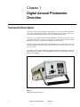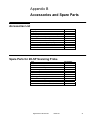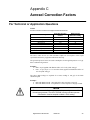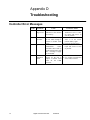
1
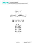
Photometers Aerosol Photometer Models 2H and 2HN Instruction Manual P/N 1800110, Revision J May 2014 ii (Intentionally Left Blank) iii Contents Sections Guidelines to use this manual...............................................................................vi Symbols ...................................................................................................... vii Conventions ................................................................................................ vii Digital Aerosol Photometer Overview ...................................................................2 Instrument Description..................................................................................2 Filter Leak Testing: The Most Common Application.....................................3 How the Photometer Operates .....................................................................4 Unpacking and Setting Up the Digital Aerosol Photometer ................................6 Unpacking .....................................................................................................6 Installation.....................................................................................................7 Description of the Digital Aerosol Photometer Controls and Indicators .........10 Front Panel Connectors and Indicators ......................................................10 Front Panel Keypad ....................................................................................12 Rear Panel Connectors ..............................................................................13 RS-232 Side Port ........................................................................................15 Operating Instructions for the Aerosol Photometer ..........................................16 Initialization .................................................................................................16 Setting Parameters .....................................................................................17 L0 – Enter/Exit ............................................................................................18 L1 – Audible Alarm ON/OFF.......................................................................18 L2 – 0% Sampling Time .............................................................................19 L3 – 100% Sample Time ............................................................................19 L4 – Decimal Places to be displayed .........................................................20 L5 – Internal Reference Base .....................................................................20 L6 – Hour Meter ..........................................................................................21 L7 – Load Factory Defaults ........................................................................21 L8 – Software Revision...............................................................................22 L9 – Bargraph Display ................................................................................22 L10 – % Leakage Display Intensity ............................................................23 L11 – 0% Purge Time .................................................................................23 L12 – 100% Purge Time .............................................................................24 Setting up the Alarm Functions ..................................................................24 Changing the Reference.............................................................................25 Upstream Aerosol Measurements (DOP or PAO) ......................................25 Measuring “% Leakage” with a User Defined Reference (USER)..............26 Testing with the 2H .....................................................................................27 Verifying the Upstream Concentration during Testing ...............................27 Maintaining and Servicing the Aerosol Photometer ..........................................28 Maintenance ...............................................................................................28 General Maintenance Procedures ..............................................................28 Specifications ........................................................................................................30 Specifications..............................................................................................30 iv Accessories and Spare Parts ...............................................................................31 Accessories List ..........................................................................................31 Spare Parts for 2H-SP Scanning Probe .....................................................31 Spare Parts Kit for 2H .................................................................................32 Spare Parts Kit for 2H-N .............................................................................32 Aerosol Correction Factors ..................................................................................33 For Technical or Application Questions ......................................................33 Troubleshooting ....................................................................................................34 Controller Error Messages..........................................................................34 Contacting ATI .......................................................................................................35 For Technical or Application Questions ......................................................35 For Customer Service.................................................................................35 Warranty .................................................................................................................36 Declaration of Conformity .............................................................................37 Quick Setup Reference .........................................................................................38 Setup .......................................................................................................................38 Audible Alarm (ON) or (OFF) ................................................................................38 Internal Reference .................................................................................................38 Setting 100% ..........................................................................................................39 Optics and Flow LEDs ...........................................................................................40 Manual Revision History .......................................................................................41 Figures Figure 1 Digital Aerosol Photometer, 2H ................................................................................ 2 Figure 2 Front Panel - Aerosol Photometer, 2H.................................................................... 10 Figure 3 Keypad - Aerosol Photometer, 2H .......................................................................... 12 Figure 4 Rear Panel - Aerosol Photometer, 2H .................................................................... 13 Figure 5 RS-232 Side Port - Aerosol Photometer, 2H .......................................................... 15 Tables Table 1 Packing List for the Digital Aerosol Photometer Model 2H ........................................ 6 Table 2 Serial Port Settings for communication with the 2H ................................................. 15 Table 3 2H Programmable parameters and associated functions ........................................ 17 Table 4 Specifications of the Digital Aerosol Photometer Model 2H ..................................... 30 Table 5 Aerosol Correction Factors for the Digital Photometer Model 2H ............................ 33 v (Intentionally Left Blank) vi Guidelines to use this manual Symbols The following symbols are used throughout the manual to draw attention to items or procedures that require special notice or care. Operator required action. Note Contains important information that, if ignored, can cause inaccurate readings. Caution Contains information that, if ignored, can cause equipment damage. Warning Contains information that, if ignored, can cause injury or death to those handling the equipment. Conventions [Window] Indicates the information displayed in a window on the Control Panel. <Function> indicates a button on the Control Panel. vii (Intentionally Left Blank) viii Chapter 1 Digital Aerosol Photometer Overview Instrument Description The 2H is a forward light-scattering, linear photometer. It operates on 100 to 240 Volts, 50 or 60 Hz, adjusting automatically. The basic function of the 2H is to sample air or other gases and report the mass concentration of particulates in the sample. This unit is also available in a nuclear version, the 2H-N. The nuclear version is the same size and has the same features as the 2H, plus a sealed sampling chamber and an additional ULPA filter to contain all contamination within the unit. The 2H is compact and lightweight. The instrument case is constructed of die cast aluminum and has a swing arm carrying handle that folds up under the case to tilt the unit for easy viewing. The pressure-sensitive keypad and large, bright LED displays and indicators provide ease of operation and readability. The auto-ranging and one-step zeroing features assure the accuracy of all readings. Figure 1 Digital Aerosol Photometer, 2H 2 Digital Aerosol Photometer Model 2H Filter Leak Testing: The Most Common Application The most common application of the Aerosol Photometer 2H is to detect leaks in high efficiency filter systems (HEPA & ULPA). To establish the integrity of a filtration system, a challenge agent consisting of an airborne test aerosol is generated and introduced upstream of the filter. The challenge agent is used to provide enough particulate matter upstream of the filter to allow statistically valid measurements downstream of the filter. The test aerosol should be introduced into the upstream side of the filter(s) as far from the filters as is practical to insure adequate mixing. 10 duct diameters are considered ideal. A sample of the aerosol-air mixture should be taken from the upstream side, close to the center of the filters. This sample is used to set the 100% base line since it is the concentration of the challenge aerosol. The apparatus is adjusted as described in the Operating Section to set the 100% reading and then the stray light is adjusted. The stray light adjustment is necessary to compensate for any signal caused by dark current or reflection of internal surfaces of the scattering chamber. After these adjustments have been made the equipment is ready to check leaks on the downstream side of the filters. The filter test is performed with the use of the optional scanning probe. The filter and the perimeter of the filter pack should be scanned by passing the probe in slightly overlapping strokes so the entire area of the filter is sampled. The end of the probe should be held one inch from the filter surface. Separate passes should be made around the entire periphery of the filter, along the bond between the filter pack and the frame, and around the seal of the filter. Readings on the meter will indicate percent of penetration. The display indicates the percent of leakage through or around the filter. The scanning probe is supplied with 3 types of nozzles that can be attached to the end of the flexible probe. The round, black nozzle is 1 inch (25 mm) in diameter, which complies with NSF (National Sanitation Foundation) Standard 49-1992. The rectangular, blue isokinetic nozzle is used for faster scanning and is accepted by many standards, including NSF 492002. The round, red nozzle is also an isokinetic nozzle. The isokinetic nozzles are designed for face velocities of 90 +/- 20 feet per minute (fpm) when using a 1 cfm (28.3 L/min) sample rate. Digital Aerosol Photometer Model 2H 3 How the Photometer Operates Theory of Operation When air or gas is drawn through the scattering chamber, particulate matter in the sample passes through the focal point of the scattering chamber. Particulate matter scatters light into the dark cone and onto the photomultiplier tube, which converts the light into an electrical signal. The signal is amplified and digitized, then analyzed by a microprocessor to determine the intensity of the light scattered by the signal. This signal is then compared to a reference signal to provide an output that is normalized by the reference signal. A photometer is ideally suited to detect particulate matter in air or gas, reporting the mass concentrations encountered on a display. Particles from less than 0.1 micron to approximately 600 microns can be detected by the 2H. Since the photometer reports concentration of particulate matter, many applications are possible. By using a baseline of 100 micrograms per liter of aerosol, it is possible to directly read the concentrations of aerosol. Sampling System A vacuum pump provides a sample flow rate of 1 cfm (28.3 liters per minute) for the instrument. It is an oil-free, dual head, rotary vane pump with a direct-coupled DC motor. A selector valve on the front panel directs the airflow through the sampling system to the scattering chamber from three possible sources. The CLEAR position directs clean air from an internal ULPA filter to the scattering chamber for zeroing the instrument. The UPSTREAM position permits sampling of the air above the filter being challenged, and the DOWNSTREAM position permits sampling of the air that penetrates the filter. Light Scattering Chamber (LSC) The scattering chamber is not only an integral part of the sampling system; it is a major component in itself. The scattering chamber is a complex electro-optical unit that consists of a pair of hollow cones connected at the apexes. A pair of collimating lenses first straightens the light emerging from the light source, and then focuses it at the center of the sampling cone. An aperture forms a dark cone around the photomultiplier, preventing light from arriving directly on the photomultiplier. A condensing lens opposite the LED source focuses light scattered into this dark cone onto the photomultiplier tube. Amplifier The signal from the photomultiplier tube in the scattering chamber is delivered to an FET operational amplifier capable of a gain increase of 2,500,000. The amplifier augments the phototube signal in a linear fashion and delivers the signal to an analog-to-digital converter that is then sent to the microprocessor. 4 Digital Aerosol Photometer Model 2H Capabilities Note Before attempting to operate this unit, become familiar with the features and functions. The Aerosol Photometer 2H will measure percentage leakage or absolute aerosol concentration Input / Output features Alarm (audible and visual): When a reading exceeds the user selected alarm point the display will flash on and off and a tone will sound if enabled. Serial Data Output: % Leakage data is sent out the unit’s serial port. This data can be logged on ATI’s DAS1 or DAS2 data acquisition systems. The following are screenshots of the DAS1 interface. Contact ATI or your local representative for more information about the data acquisition systems available from ATI. Digital Aerosol Photometer Model 2H 5 Chapter 2 Unpacking and Setting Up the Digital Aerosol Photometer Unpacking Carefully unpack and remove the Digital Aerosol Photometer Model 2H and all accessories from its shipping container. If the instrument has been damaged in transit, notify the shipper immediately. The Digital Aerosol Photometer Model 2H (93001331) and Model 2H-N (93001472) consist of a photometer and accessories, including the following: Table 1 Packing List for the Digital Aerosol Photometer Model 2H Qty. 1 1 1 1 1 Item 2H Unit Power Cord 12 feet of clear PVC tubing Operating Manual Calibration Certificate Part Number 0200301 67000013 5200116 1800110 N/A The following items are optional. Check the order packing slip. Qty. 1 1 1 1 1 1 Item 2H-SP Scanning Probe, complete Shipping Case Round isokinetic nozzle (red) Rectangular isokinetic nozzle (blue) NSF 1” round nozzle (black) 2H-SP Scanning probe Part Number 9300144 9300145 T2E0-0572 T2E0-0798 T2E0-0005 T2SP-0881 After unpacking, if anything is missing or appears to be damaged, contact ATI Customer Service at (410) 363-9696. Note ATI recommends that you save all packing materials for future use, such as shipping the unit back for annual calibration. Warning If the unit is used in a manner not specified within the user’s manual, the protection offered by the equipment may be impaired. 1 This part number applies to the 110V version. The part number for the 220V version is 9300134. This part number applies to the 110V version. The part number for the 220V version is 9300148. 3 This part number applies to the 110V version. The part number for the 220V version is 6700133. 2 6 Digital Aerosol Photometer Model 2H Installation Before you begin You will need the following items to set up the Aerosol Photometer Model 2H An electrical outlet (110 VAC or 220 VAC). 2H-SP Scanning Probe or PVC Sampling Tube Operating Range: 35 to 105 degrees Fahrenheit An environment with less than 75% relative humidity. Note High ambient temperatures may create instability in the readings Connecting Electrical Power Voltage and current requirements for the Aerosol Photometer Model 2H are: 100 to 120 VAC, 5 amps, or 220 to 240 VAC, 2.5 amps The Aerosol Photometer automatically adjusts to operate at the correct AC voltage for the destination country (given this voltage is within the specifications described in Appendix A). This voltage is noted on a label attached to the back panel of the instrument. The power cord contains a plug which is specifically adapted to the destination country. You are responsible for plugging the power cord into a matching receptacle. To connect the Aerosol Photometer to electrical power, do the following: 1. Check to make sure the Aerosol Photometer is turned off. (Refer to figure 4 for the location of the power switch.) 2. Plug the power cord into a matching power outlet. Warning Before connecting the power cord to the power outlet, make sure the cord has not been cut or otherwise damaged during shipment. Caution To prevent damage to the Aerosol Photometer, make sure the voltage listed on the back panel matches the power outlet where you plug it in. Digital Aerosol Photometer Model 2H 7 Connecting the Scanning Probe If using the Digital Aerosol Photometer 2H with the Scanning Probe, connect the probe’s electrical connector to the 12-pin connector on the front panel of the unit before applying power to the photometer. Otherwise, the display on the Scanning Probe will not function. Connect the probe’s sampling hose to the barbed “DOWNSTREAM” fitting to the right of the 12-pin connector. The cable and sampling hose are bound as a single, flexible umbilical. Select the appropriate probe nozzle and screw it onto the threaded end of the flexible portion of the Scanning Probe. Note When using the 2H-SP Scanning Probe with the 2H, the probe must be connected to the photometer before the power is turned on. Otherwise the 2H will not detect the probe and no display will be observed on the pistol grip. If this occurs, switch the power off, verify that the probe is connected properly, and then switch the power back on. 8 Digital Aerosol Photometer Model 2H (Intentionally Left Blank) Digital Aerosol Photometer Model 2H 9 Chapter 3 Description of the Digital Aerosol Photometer Controls and Indicators Front Panel Connectors and Indicators Front Panel Display Bar Graph Display Function Keys Selector Valve Upstream Sample Port Scanning Probe Ground Jack Scanning Probe Connector Optics Indicator Light Downstream Sample Port Optics Indicator Light Figure 2 Front Panel - Aerosol Photometer, 2H 10 1. 2. Front Panel Display Bar Graph Display 3. Function Keys 4. 5. Selector Valve Upstream Sample Port Digital Aerosol Photometer Indicates % leakage readings and error messages. Displays an analog representation of the % leakage to aid in isolating leaks. Used for setting operating parameters and initiating program routines Selects the sample source. Connects to the sample tubing that is used to measure the upstream aerosol concentration. Model 2H 6. Probe Ground Jack 7. Scanning Probe Connector 8. 9. Downstream Sample Port Optics Indicator Light Green Light Orange Light Red Light Less than 10,000mg* of aerosol has moved through the scattering chamber. More than 10,000mg* but less than 17,000mg* of aerosol has moved through the scattering chamber. More than 17,000mg* of aerosol has moved through the scattering chamber. Servicing of the unit is highly recommended. 10. Flow Indicator Light Green Light Orange Light Red Light Electrical ground connection for scanning probe shielding. (Required for CE compliance) Electrical connection for the optional Scanning Probe. Connects to the respirator sample tubing. Corresponds to the cleanliness of the optics. Indicates the status of the flow meter. The flow is within 5% of 1 CFM. The flow is between 5% and 10 % of 1 CFM. The flow is more then 10% above 1 CFM. Note These values are approximate. Actual mass may vary with different airflow rates and aerosols. Digital Aerosol Photometer Model 2H 11 Front Panel Keypad Figure 3 Keypad - Aerosol Photometer, 2H The front panel contains seven pressure-activated function keys. The <0>, <100>, <REF>, and <ALARM> keys each contain a red LED to indicate the state of the switch or to prompt the operator. The <> and <> keys are used to scroll between selections as they are shown on the “% LEAKAGE” display. The <ENTER> key serves as the command key for sending information to the processor and for initiating or stopping system routines. The <>, <>, and <ENTER> keys contain no indicator LED. The “% LEAKAGE” display is an array of high-visibility LED’s that forms a display screen. The Front Panel Display shows alphanumeric messages. Underneath it, a “Bar Graph Display” gives a visual indication of the internal photometer cycling or an analog representation of quantity or percentage. The Scanning Probe contains an unlabeled display on the pistol grip that is a half-scale duplicate of the “% LEAKAGE” Indicator. The two displays are driven by the same electronics and will always read exactly the same. 12 Digital Aerosol Photometer Model 2H Rear Panel Connectors Cooling Fan Vacuum Pump Exhaust Calibration Sticker Serial Number Label Power Connector Power Switch Fuse Block Figure 4 Rear Panel - Aerosol Photometer, 2H 1. 2. 3. 4. 5. 6. 7. Cooling Fan: Maintains airflow through the unit’s enclosure to stabilize electronics. Calibration Sticker: Displays the current calibration date and the due date for the next calibration Power Connector: Connects to the Power Cord. Fuse Block: Contains two 2-amp slow blow fuses. Vacuum Pump Exhaust: Allows a filter to be installed to eliminate particulate emissions. Serial Number Label: Lists the model, serial number and utility requirements. Power Switch: Turns the system power on and off. The rear panel contains a recessed, 3-pronged male Power Connector, with an integral fuse block and power switch, and a Vacuum Pump Exhaust HEPA Filter. Caution The 2H should always be positioned so that the Power Switch, located on the rear panel, is readily accessible in the event the unit needs to be powered off quickly. Digital Aerosol Photometer Model 2H 13 The Power Connector accepts the female end of the Power Cord that comes with the unit. The internal power supply is a universal supply that can operate at either 50 or 60 Hz and with any voltage from 90 to 240 volts, for use in virtually all countries. Therefore, any plug with the correct female end (IEC-320 standard) may be attached to the unit and the universal power supply will automatically switch to use the supplied input power. The Vacuum Pump Exhaust HEPA Filter is provided so that the sensitive environments of cleanrooms can be maintained. The air expelled by the unit is continually filtered of all particulate matter generated by testing aerosols and the unit using this HEPA exhaust system. 14 Digital Aerosol Photometer Model 2H RS-232 Side Port The Digital Aerosol Photometer 2H features an RS-232 connector located on the side of the unit in the form of a 9-pin female D-subminiature connector. The % Leakage data is continuously sent via the RS-232 port as it is updated on the Front Panel Display, approximately once per second. It is recommended that this data be logged by either one of ATI’s data acquisition systems, the DAS1 or the DAS2. Contact ATI or your local representative to learn more about data logging options. If using a terminal program package such as Windows Hyper-terminal, a straight cable must be used (as opposed to a null modem cable). If using a Pocket PC (PPC) to receive data, the type of cable will depend upon the brand of PPC. Contact ATI customer service for complete details. Figure 5 RS-232 Side Port - Aerosol Photometer, 2H The 2H serial port settings are described in the following table. Table 2 Serial Port Settings for communication with the 2H Bits per second Data bits Parity Stop bits Flow Control Digital Aerosol Photometer 2400 8 None 1 None Model 2H 15 Chapter 4 Operating Instructions for the Aerosol Photometer Initialization Apply power to the 2H by setting the rocker switch to the 1 position (On). Verify that the selector valve knob is turned to the “CLEAR position”. Verify that the display is fully lit displaying [88888] with a fully illuminated bar graph beneath. (This display must occur before the 2H is ready to use.) The following events will occur: 1. The display will show [88888] 2. All of the LEDs in the bar graph will be illuminated (“Bar Graph” scans for 20 seconds). 3. The LEDs in the 0, 100, REF, and ALARM buttons will be illuminated. 4. A short beep will sound. 5. The flow sensor indicator LED on the front panel becomes active. These events indicate that the unit has started and also give the user the opportunity to check the integrity of all the LEDs with the exception of the “OPTICS” LEDs. The “FLOW” LED will be green, yellow, or red. The “OPTICS” LED will be off at this time. After a few moments, the firmware revision (main PCB) will be displayed. Next the screen will go blank and, after a few more moments, another short beep will sound. The reference light will blink, indicating that it is time to select a reference. Follow these steps to complete the setup: 1. 2. 3. 4. 5. 6. Press <ENTER>. Use the <> (Up) and <> (Down) function keys to select the reference of choice. Press <ENTER>. Use the <> (Up) and <> (Down) function keys to select the internal reference factor. Press <ENTER>. The unit will scan while adjusting the detector gain level. The <0> LED will begin to blink indicating that it is time to set the zero reference. Double check the selector valve is set to clear. 7. Press <ENTER>. The bar graph display will indicate that the unit is sampling the zero reference value. Upon completion, a short tone will sound and the unit will begin sampling and sending data via the serial port. 16 Digital Aerosol Photometer Model 2H Setting Parameters The Digital Aerosol Photometer 2H has twelve operating parameters (not counting L0), eight of which are programmable by the operator to facilitate setting up the instrument for operation. Some of these parameters have been factory set, but can be optionally reset by the operator. If required, these parameters can be returned to the factory default setting at any time. Other parameters are accessible for programming only at the factory. The eleven parameters, and their default settings, are listed in this addendum. Table 3 2H Programmable parameters and associated functions Parameter L0 L1 L2 L3 L4 L5 Function Run Audible Alarm 0% Sample Time 100% Sample Time Decimal Places Internal Reference L6 L7 L8 L9 L10 L11 L12 Hour Meter Load factory defaults Software Revision Bar Graph Display Display Intensity Adjustment 0% Purge Time 100% Purge Time Valid Range ON / OFF 5 – 120 seconds 5 – 120 seconds 3–4 DOP, PAO, USER, HIGH ON / OFF 1–8 0 – 120 seconds 0 – 120 seconds Default Value OFF 10 seconds 10 seconds 4 DOP ON 6 0 0 To enter the parameters setting menu proceed as follows: 1. 2. Press <> function key (Up arrow). The display will read [- - - - -]. Press <ENTER> function key. The first parameter L0 will be displayed on the “% LEAKAGE” indicator. Note If the <ENTER> key is not pressed within about 3 seconds, the unit will assume this was an accidental key press and return to sampling mode. 3. 4. 5. 6. 7. The <> (Up) and <> (Down) function keys are used to scroll through the parameters from L0 to L12. To access a parameter once it is displayed, press the <ENTER> function key. Select the desired setting for the parameter by using the <> (Up) and <> (Down) function keys. When the desired setting is displayed, press the <ENTER> function key to store the setting. Following the selection of the parameter setting, the display will return to the main parameter menu, ready to select either another parameter or L0 to return to sampling mode. Digital Aerosol Photometer Model 2H 17 L0 – Enter/Exit This is a non-programmable parameter. This parameter is used to both enter and exit the parameter setting menu. When L0 is selected, the programmable parameter settings are included in the operating routine. Scroll to L0 and press <ENTER> to return to running mode. L1 – Audible Alarm ON/OFF Options: (-) Off (1) On Default: Off Enables or disables the audible portion of the 2H alarms. The unit parameter is factory set to off. When [L1] is displayed in the parameter menu, press the <ENTER> function key to access the stored setting. A [–] appearing in the % Leakage display indicates that this parameter is currently disabled. A [1] indicates an active parameter. Press the <> (Up) and <> (Down) function keys to change the displayed setting between 0 (disabled) and 1 (enabled). Press <ENTER> to set the selection and return to the parameter select menu ([L1] will be displayed). 18 Digital Aerosol Photometer Model 2H L2 – 0% Sampling Time Options: 5 – 120 seconds Default: 10 seconds Establishes the period over which the 0% aerosol sample is average. When [L2] is displayed in the parameter menu, press the <ENTER> function key to access the stored setting. Press the <> (Up) and <> (Down) function keys to move the displayed setting between 5 and 120 on the display. Press <ENTER> to set the selection and return to the parameter select menu ([L2] will be displayed). L3 – 100% Sample Time Options: 5 – 120 seconds Default: 10 seconds Establishes the period over which the 100% aerosol sample is averaged. This frequency is relative to the cycling of the system microprocessor and is not time dependent. When [L3] is displayed in the parameter menu, press the <ENTER> function key to access the stored setting. Press the <> (Up) and <> Down) function keys to move the displayed setting between 5 and 120 on the display. Press <ENTER> to set the selection and return to the parameter select menu ([L3] will be displayed). Digital Aerosol Photometer Model 2H 19 L4 – Decimal Places to be displayed Options: 3–4 Default: 4 This parameter is used to select either 3 or 4 decimal places on the % Leakage Display. When [L4] is displayed in the parameter menu, press the <ENTER> function key to access the stored setting. Press the <> (Up) and <> (Down) function keys to move the displayed setting between 3 and 4 on the display (3=0.001%, 4=0.0001%). Press <ENTER> to set the selection and return to the parameter select menu ([L4] will be displayed). L5 – Internal Reference Base Options: DOP PAO USER HIGH Default: DOP Establishes the internal reference base response based upon a gain setting stored during factory calibration. When [L5] is displayed in the parameter menu, press the <ENTER> function key to access the stored setting. Press the <> (Up) and <> (Down) function keys to move the displayed setting between DOP, PAO, USER or HIGH. Note Refer to section “Changing the Reference” to change the selection or reestablish internal reference. See Appendix C “Aerosol Correction Factor” for correction factors to be used in conjunction with other challenge aerosols. Press <ENTER> to set the selection and return to the parameter select menu ([L5] will be displayed). 20 Digital Aerosol Photometer Model 2H L6 – Hour Meter Options: None Default: None This option displays the total running time for the unit. When [L6] is displayed in the parameter menu, press the <ENTER> function key to access the hour value. Press <ENTER> to set the selection and return to the parameter select menu ([L6] will be displayed). L7 – Load Factory Defaults Options: (- - - - -) Not enabled (LOAD) Enabled Indicating factory default loading has not been selected Indicating factory default loading has been selected Default: (- - - - -) Not enabled This option is used to restore the factory default settings to all the user programmable parameters. When [L7] is displayed in the parameter menu, press the <ENTER> function key to access the stored setting. Press the <> (Up) and <> (Down) function keys to move the displayed setting between (- - - - -) and (LOAD). Press <ENTER> to set the selection and return to the parameter select menu ([L7] will be displayed). Digital Aerosol Photometer Model 2H 21 L8 – Software Revision Options: None Default: None This option is used to display the current revision used by the 2H firmware L9 – Bargraph Display Options: OFF – Disabled ON – Enabled Default: ON – Enabled This option is used to enable or disable the analog bargraph display beneath the numeric portion of the % Leakage display. When [L9] is displayed in the parameter menu, press the <ENTER> function key to access the stored setting. Press the <> (Up) and <> (Down) function keys to move the displayed setting between ON and OFF on the display. Press <ENTER> to set the selection and return to the parameter select menu ([L9] will be displayed). 22 Digital Aerosol Photometer Model 2H L10 – % Leakage Display Intensity Options: 1–8 Default: 5 This option is used to adjust the intensity of the green LED display in the % Leakage display. When [L10] is displayed in the parameter menu, press the <ENTER> function key to access the stored setting. Press the <> (Up) and <> (Down) function keys to move the displayed setting between 1 and 8 on the display. Press <ENTER> to set the selection and return to the parameter select menu ([L10] will be displayed). L11 – 0% Purge Time Options: 0 – 120 seconds Default: 0 seconds Set the length of time for the system to run before taking reading when calculating the zero value. When [L11] is displayed in the parameter menu, press the <ENTER> function key to access the stored setting. Press the <> (Up) and <> (Down) function keys to move the displayed setting between 0 and 120 on the display. Press <ENTER> to set the selection and return to the parameter select menu ([L11] will be displayed). Digital Aerosol Photometer Model 2H 23 L12 – 100% Purge Time Options: 0 – 120 seconds Default: 0 seconds Set the length of time for the system to run before taking reading when calculating the 100% value. When [L12] is displayed in the parameter menu, press the <ENTER> function key to access the stored setting. Press the <> (Up) and <> (Down) function keys to move the displayed setting between 0 and 120 on the display. Press <ENTER> to set the selection and return to the parameter select menu ([L12] will be displayed). Setting up the Alarm Functions The 2H has an alarm feature which can alert the user when particle concentration exceeds a user-selected “% Leakage” value. To set the alarm features, perform the following steps: 1. 2. 3. 4. 5. 6. 7. 8. 24 After system initialization, press the <ALARM> function key. The <ALARM> LED will flash and the current alarm setting ([ON] or [OFF]) will be displayed. Press the <> (Up) and <> (Down) function keys to change the displayed setting. If changing the alarm set point is not desired, the <ENTER> function key may be pressed to return to sampling mode. If this is the case, press <ENTER> and proceed to step 8. If the alarm set point is to be changed or checked, press the <ALARM> function key again to enter the set point mode. Press the <> (Up) and <> (Down) function keys to change the displayed set point. Press the <ENTER> key two times to return to the unit to sampling mode. Setup of the alarm is now complete. When the measured concentration exceeds the set point, the display with flash. If the audible alarm parameter (L1) is set to “ON”, a tone will also be heard. Digital Aerosol Photometer Model 2H Changing the Reference During the initialization sequence immediately following unit startup, the user is required to select a reference. To change the desired reference anytime thereafter, perform the following steps: 1. 2. 3. Press the <REF> function key. The <REF> LED will flash and the display will go blank. Press the <ENTER> function key. If the <ENTER> key is not pressed within about three seconds, the unit will return to sampling mode. 4. Use the <> (Up) and <> (Down) function keys to select the desired reference. 5. Press the <ENTER> function key. 6. Use the <> (Up) and <> (Down) function keys to select the desired internal reference factor. 7. Press the <ENTER> function key. The <0> LED will begin to blink indicating that it is time to set the zero reference. Double check the selector valve is set to clear. 8. Press <ENTER>. The bar graph display will indicate that the unit is sampling the zero reference value. Upon completion, the unit will return to the sampling mode. Upstream Aerosol Measurements (DOP or PAO) Note Do not perform the steps in this section until completing the steps described in the “Initialization” section. Note If there is a concern that the zero baseline may have drifted, the operator may re-zero the instrument at any time by positioning the selector valve to the clear position, pressing the <0> button and pressing <ENTER>. Warning The unit should be placed on a flat, stable surface with the area to be monitored within reach of the sample lines. Digital Aerosol Photometer Model 2H 25 1. Insert the “UPSTREAM” sample line into the upstream aerosol / air mixture. Note The sample line should be as close to the upstream side of the filter as possible. 2. Turn the Selector Valve to the “UPSTREAM” position. This switches the sample airflow to the “UPSTREAM” sampling port on the front panel. The “% LEAKAGE” display indicates the upstream concentration as compared to the reference that was set in the initialization section. Note Adjust aerosol for desired challenge aerosol concentration. Measuring “% Leakage” with a User Defined Reference (USER) 1. Insert the “UPSTREAM” sample line into the upstream aerosol/air mixture. Note The sample line should be as close to the upstream side of the filter as possible. 2. Turn the Selector Valve to the “UPSTREAM” position. This switches the sample airflow to the “UPSTREAM” sampling port on the front panel. The “% LEAKAGE” display indicates the upstream reading. 3. Press the <100> button and press <ENTER>. The unit will begin scanning for a 100% reference value. Note If the error [E4] is given then the 100% calibration failed. The most likely reason for this error would be an aerosol concentration too low to take an accurate reading. Press <ENTER> to clear the error. The unit defaults back to the previous reference setting. 26 4. After the 100% reference value has been successfully captured, the <0> LED will blink, indicating that the 0% reference must be calibrated. 5. Switch the selector valve to “CLEAR” and press the <ENTER> button. The unit will scan for the 0% reference value. 6. After the unit has finished scanning for the 0% reference, switch the selector valve to “DOWNSTREAM”. The “% LEAKAGE” display indicates the concentration as compared to the upstream value. Digital Aerosol Photometer Model 2H Testing with the 2H After the 100% and 0% baselines have been established, the unit is ready for testing operations. During testing operations, readings may be taken from either the Front Panel Display or the Scanning Probe, lessening operator distraction. Testing is performed as follows: 1. 2. 3. Turn the selector valve to “DOWNSTREAM” to permit sampling through the Scanning Probe. Pass the end of the probe over the filter being tested at the rate required by the standard or recommended practice being employed. Read and record the data as it is displayed on either the pistol grip of the probe or the Front Panel Display. Once the 100% baseline has been properly defined, the display readings are given directly in % leakage. Note Most current standards and recommended practices require leaks of greater than 0.01% to be identified and repaired. Verifying the Upstream Concentration during Testing Turn the Selector Valve to the “UPSTREAM” position. The “% LEAKAGE” display shows the concentration of the upstream challenge aerosol in percent of upstream calibration. The photometer is comparing the real-time concentration of the upstream challenge to the concentration of this same source when it was initially used to establish the 100% baseline. In other words, it is comparing the current concentration level to the starting level. If the reading seems reasonable, normal testing may be resumed by turning the Selector Valve back to the “DOWNSTREAM” position. If the concentration of the challenge aerosol has changed significantly, the upstream source should be examined for the cause. Once the situation has been corrected, the upstream challenge aerosol should be restarted, stabilized, and then used to re-establish the 100% baseline as described previously. Digital Aerosol Photometer Model 2H 27 Chapter 5 Maintaining and Servicing the Aerosol Photometer Maintenance Weekly Clean the scanning probe screens. These are located on the black and red circular scanning probe nozzles. Clean the gross particulate screen located at the base of the flexible scanning probe extension. Remove any loose debris from the Scanning Probe and front panel sampling ports. Annually Return the 2H to a factory authorized facility for calibration and cleaning. Please contact the ATI Customer Service Department at 410-363-9696 for a return authorization number. A service date will be scheduled for your instrument at that time. Note A Return Authorization can also be obtained using ATI’s website or by sending an e-mail requesting service information to [email protected]. A customer service representative will process your information and contact you with a Return Authorization, necessary instructions and information within 48 hours. General Maintenance Procedures The 2H Aerosol Photometer is a sturdy, solid-state electronic instrument designed to hold up under extended field use. The only moving parts are the vacuum pump, the selector valve and the ventilating fan at the rear of the chassis. Field level maintenance is limited to replacement of the HEPA exhaust filter and the fuses. Procedures for these operations are contained in this section. Note The internal electronics are not user serviceable. Any electronic problems must be analyzed and repaired at an authorized service center. 28 Digital Aerosol Photometer Model 2H There is no indicator on the front panel showing that the scattering chamber light source is not working. If the scattering chamber light source has burned out, the operator will witness a lack of response on the unit’s display. Recommended Spare Parts Spare components are not supplied with the 2H or the 2H-N nuclear unit and must be ordered separately. See Appendix B for a list of recommended spare parts that may be purchased in kit form or individually. This list includes only parts replaceable by the user in the field. Other repairs requiring instrument or component recalibration must be performed at an ATI service center. Cleaning the 2H-SP Scanning Probe Screens The 2H-SP Scanning Probe is a rugged, low maintenance device. The probe contains a coarse wire screen near the base of the flexible neck to prevent fibers and large particles from being drawn into the photometer. In addition, there are screens in each of the two round nozzles that thread onto the flexible neck. The blue rectangular nozzle contains no screen. If the screens accumulate a significant amount of debris and become partially clogged, it can interfere with the airflow and affect the accuracy of the photometer and may put an unnecessary strain on the vacuum pump. Note It is recommended that all screens be wiped clean with a lint-free cloth before use each day. If the screens are punctured, replace them immediately. Spare nozzles and replacement scanning probe components can be ordered from ATI (see Appendix B). To access the screen in the flexible neck, unscrew the flexible extension from the probe body. A small tool may be necessary to reach into the neck to remove and wipe the surface of the screen. Replacing the Main Power Fuses Position the 2H with the rear panel readily accessible. Locate the fuse block at the center of the power entry connector. Press the top and bottom tabs toward the center and pull the fuse block straight out from the power entry connector. The two fuses (ATI part # 6400001) will be exposed for inspection and/or replacement. Replace the fuse block by gently inserting it back into the power entry connector until the tabs snap back into their original location. Replacing the HEPA Exhaust Filter Position the 2H with the rear panel readily accessible. Rotate the HEPA exhaust filter in a counter-clockwise direction until the threads are free of the rear panel bushing. Install the new replacement filter (ATI part # 5500123) in the same orientation as the filter that was replaced. Care should be taken to avoid cross-threading the filter housing. When installed correctly a cylindrical well should be visible through the filter port. This design directs exhausted airflow to the outside of the filter media core, providing greater surface area and prolonging service life. Digital Aerosol Photometer Model 2H 29 Appendix A Specifications Specifications The following specifications—which are subject to change—describe the most important data regarding the Digital Aerosol Photometer 2H. Table 4 Specifications of the Digital Aerosol Photometer Model 2H Dimensions (L x W x H) English (inches) Metric (centimeters) Weight 2H TDA-2SP Input Power Fuse Dynamic Range Accuracy Repeatability Sampling rate 90 to 250 volts AC, 50 or 60 Hz, 1.5 amps 250 volts, 2.0 amps slow blow (5 x 20 mm) 0.00005 to 120 micrograms per liter 1% of full scale for the amplifier decade in use 0.5% full-scale for the amplifier decade range in use 1 CFM (28.3 L/min) Data Output RS-232 (Port settings: 2400, 8, N, 1) 13.5 x 9.5 x 5.0 34.3 x 24.1 x 12.7 15.5 lbs (7.0 kg) 2.5 lbs lbs (1.1 kg) Specifications are subject to change without notice. 30 Digital Aerosol Photometer Model 2H Appendix B Accessories and Spare Parts Accessories List Description Shipping case 2H Spare parts kit (see list below for components) 2H-N Spare parts kit (see list below for components) Scanning probe assembly, complete with 3 nozzles Replacement Line Cord, 120V (USA) Replacement Line Cord, 220V (Europe) ¼” ID PVC sample tubing (specify length) Straight-through serial cable, 6 ft. Fuse, 2 amp, 5 x 20 mm Filter, HEPA, 36mm (rear exhaust filter) Part Number 9300145 9300142 9300143 9300144 6700001 T2E0-0063 5200116 T2G0-1120 6400001 5500180 Spare Parts for 2H-SP Scanning Probe Item Part Number Segment Male threaded end segment Female threaded end segment Male close nipple Replacement probe screen, 5/16” diameter Replacement probe screen, 1-7/16” diameter Replacement probe screen, 3 1/32” diameter Scanning probe extension, 12 ft. NSF 49:1992 Scanning probe nozzle 1” Isokinetic, round (red) NSF 49:2002 Isokinetic, rectangular (blue) Screen holder assembly 5100001 5100002 5100004 5100101 T2SP-0883 T2SP-0884 T2SP-0885 T2SP-1095 T2E0-0005 T2E0-0572 T2E0-0798 0600287 Digital Aerosol Photometer Model 2H 31 Spare Parts Kit for 2H Qty. 1 Item Part Number ULPA filter (internal reference air filter) 0600424 Pump Exhaust Filter (internally mounted 2 5500002 filter) 2 HEPA filter, 36mm 5500180 1 Replacement Probe screen, 5/16” Ø T2SP-0883 1 Replacement Probe screen, 1-7/16” Ø T2SP-0884 1 Replacement Probe screen, 31/32” Ø T2SP-0885 Recommended one year consumable parts. Contact ATI Customer Service Department for more information. Spare Parts Kit for 2H-N Qty. 2 2 2 4 8 25 ft 5ft Item Part Number ULPA filter (internal reference air filter) 0600424 Selector valve T2G0-0931 Sealed cone w/ fittings T2GN-0949 Brass fittings T2G0-0907 Brass fittings 5100006 Poly-flo tubing 5200102 PVC tubing, clear 5200116 Recommended one year consumable parts. Contact ATI Customer Service Department for more information. 32 Digital Aerosol Photometer Model 2H Appendix C Aerosol Correction Factors For Technical or Application Questions Table 5 Aerosol Correction Factors for the Digital Photometer Model 2H DOP Substitute liquid DOP (DEHP) PAO (Emery 3004) DOS (DEHS) Mineral Oil Ondina Oil (Ondina EL) Kaydol Polyethylene Glycol (PEG400) Paraffin Oil Corn Oil Generator Pressure Factors 1.00 1.15 1.22 1.10 1.34 1.18 1.33 1.21 1.17 DOP Internal Reference Setting 100 73 96 90 79 92 111 89 88 The above values are for use when substitute liquids are used in-place of the liquid specified for the Factory equipment calibration and setup. The generator pressure factors are used as multipliers for the applied pressure to a Type III-A Laskin nozzle generator. Example: DOP - 20 psi applied with dilution airflow of 135 cfm yields 100 µg/l. PAO - 23 psi (20 psi x 1.15 correction factor) applied with dilution airflow of 135 cfm yields 100 µg/l. The above DOP settings are required for a 100% reading of 100 µg/l of the DOP substitute liquid. Example: DOP with DOP selected - 100 required for 100% response to 100 µg/l. DOS with DOP selected - 96 required for a 100% response to 100 µg/l of DOS. Note The above correction factors apply only to air operated generators. If a thermal type generator, TDA-5A or TDA-5B, is being used the upstream concentration must be sampled to obtain a 100% setting. Digital Aerosol Photometer Model 2H 33 Appendix D Troubleshooting Controller Error Messages Error Code E1 34 Problems Cause Corrective Action Calibration flags not set. The unit has not been calibrated or the unit has lost memory. E2 LSC voltage not stable. E3 Optics Dirty E4 100% calibration failed Concentration readings are not stable enough to perform a reliable 100% or 0%. Sufficient aerosol condensation and/or particulates have built up on the internal optics such that a cleaning is highly recommended. There is insufficient aerosol for the unit to capture a reliable 100% value for the USER reference. Return the unit to ATI or Authorized service center for repair and service as soon as possible. 1. Ensure that the selector valve is in the correct position and try again. 2. Check the aerosol source. Return the unit to ATI for repair and service as soon as possible. Digital Aerosol Photometer Model 2H 1. Check the aerosol source. 2. Use a higher concentration as the 100% reference. Appendix E Contacting ATI For Technical or Application Questions If you have any difficulty setting up the Digital Aerosol Photometer Model 2H or application questions about this instrument, contact an applications engineer at ATI (410) 363-9696. For Customer Service If the Digital Aerosol Photometer 2H is not operating properly, or if you are returning the instrument for service, contact ATI Customer Service (410) 363-9696. Customer Service will need this information when you call: The instrument model number The instrument serial number A purchase order number (unless under warranty) A billing address A shipping address. Use the original packing material to return the Digital Aerosol Photometer Model 2H to ATI. If you no longer have the original packing material, use sufficient packing material so the instrument is not damaged during shipping. Digital Aerosol Photometer Model 2H 35 Appendix F Warranty Part Number Address Phone No. Fax No. E-mail Address Limitation of Warranty and Liability 1800110 / Revision H/ February 2008 Air Techniques International / 11403 Cronridge Drive / Owings Mills, MD 21117 / USA (410) 363-9696 (410) 363-9695 [email protected] Air Techniques International, hereinafter referred to as ATI, warrants the equipment purchased hereunder to be free from defect in materials and workmanship under normal use and service, when used for the purpose for which it is designed, for a period of (1) one year from the date of shipment. ATI further warrants that the equipment will perform in accordance with the technical specifications accompanying the formal equipment offer. ATI will repair or replace any such defective items that may fail within the stated warranty period, PROVIDED: a. That any claim of defect under this warranty is made within thirty (30) days after discovery thereof and that inspection by ATI, if required, indicates the validity of such claim to ATI’s satisfaction. b. That the defect is not the result of damage incurred in shipment to or from our factory. c. That the equipment has not been altered in any way whether as to design or use, whether by replacement parts not supplied or approved by ATI, or otherwise. d. That any equipment or accessories furnished but not manufactured by ATI, or not of ATI design, shall be subject only to such adjustments as ATI may obtain from the supplier thereof. ATI’s obligation under this warranty is limited to the repair or replacement of defective parts with the exception noted above. If the equipment includes a scattering chamber, ATI’s warranty does not extend to contamination of the scattering chamber by foreign material. At ATI’s option, any defective equipment that fails within the warranty period shall be returned to ATI’s factory for inspection, properly packed with shipping charges prepaid. No equipment shall be returned to ATI without prior issuance of a return authorization by ATI. Service Policy 36 No warranties, express or implied, other than those specifically set forth herein shall be applicable to any equipment manufactured or furnished by ATI and the foregoing warranty shall constitute the Buyer’s sole right and remedy. In no event does ATI assume any liability for consequential damages, or for loss, damage or expense directly or indirectly arising from the use of ATI products, or any inability to use them either separately or in combination with other equipment or materials or from any other cause. Our service policy is designed to give prompt attention to any problems. If you encounter a defective product or discover a malfunction, please call ATI Customer Service to obtain a return authorization at (410) 363-9696. Digital Aerosol Photometer Model 2H Appendix G Declaration of Conformity We: AIR TECHNIQUES INTERNATIONAL 11403 Cronridge Drive Owings Mills Maryland 21117-2247 USA Tel: (410) 363-9696 Fax: (410) 363-9695 Website: http://www.atitest.com Declare under our sole responsibility that the product, 2H Digital Aerosol Photometer is in conformity with the following directives: Application of Council Directive(s) Electromagnetic Compatibility Directive (89/336/EEC) Low Voltage Directive (73/23/EEC) Standard(s) to which Conformity is Declared EN 61326-1:1998 EN 61010-1:2001 Design documentation is maintained at: Air Techniques International 11403 Cronridge Drive Owings Mills, Maryland 21117-2247 USA Eric Hanson President Air Techniques International Digital Aerosol Photometer Date of Issue: Place of Issue: Model 2H 02 September 2003 Owings Mills, Maryland 21117-2247 USA 37 Appendix H Quick Setup Reference Setup To enter setup, press <> then <ENTER> Press <> or <> then <ENTER> to select function, then <> or <> to change. L0 L1 L2 L3 L4 L5 L6 L7 L8 L9 L10 L11 L12 Run Audible Alarm (On/Off) 0 Sample Time (5 to 120 seconds) 100% Sample Time (5 to 120 seconds) Decimal Places (3 or 4) Internal Reference (Current Selection Displayed) Hour Meter Factory Defaults Software Revision Bar graph (On/Off) Display Intensity Zero Purge Time (0 to 120 seconds) 100% Purge Time (0 to 120 seconds) Audible Alarm (ON) or (OFF) <ALARM> <ALARM> <ENTER> <ENTER> Displays Status (On or Off ), <> or <> to change, <ENTER> to exit, Pressed a second time before <ENTER>, displays Set Point, (0.010 by default) <> or <> to change. Accept Alarm Set Point. Displays On/Off status again, <> or <> to change. Accept status and return to run mode. “ALARM” LED will remain lit. Note L1 to turn the audible portion of the alarm On or Off. Internal Reference Set Selector Valve to “CLEAR” <REF> <ENTER> 38 (Blinks) Calibration reagent (PAO or DOP), also *USER or *HIGH Use <> or <> to change Digital Aerosol Photometer Model 2H <ENTER> <ENTER> Displays µg/l of concentration to be displayed as 100 when sampled. Use <> or <> to change (<0> Blinks) Ready for Testing *USER is a stored sampled concentration saved by the user, to be displayed as 100%. This value is stored in memory until a new value is sampled and saved by the user. To set: After completing the setting 100% procedure below, Press the <REF> and [USER] will be displayed. Press <ENTER>, <0> will blink; turn the Selector Valve to “CLEAR”, and press <ENTER>. *HIGH allows sampling of concentrations above 130µg/L, exceeding 200µg/L. This setting should only be used for sampling quickly and sparingly, as such concentrations will adversely affect the cleanliness of the optics. Setting 100% Connect Upstream Sample Line & set Selector Valve set to “UPSTREAM” <100> <ENTER> <ENTER> <100> key LED flashes “Bar graph” scans .The unit averages 100% for a time defined by the L3 setting. When the <0> LED flashes turn the Selector Valve to “CLEAR”. Sets 0%. Note This setting can be saved by pressing <REF>, <ENTER>, and resetting 0). (See *USER above) Ready for Testing Digital Aerosol Photometer Model 2H 39 Optics and Flow LEDs Optics LED: Green Orange Red Optics clean. Less than 10,000mg** of aerosol has moved through the scattering chamber. More than 10,000mg, but less than 17,000mg**, of aerosol has moved through the scattering chamber. More than 17,000mg** of aerosol has moved through the scattering chamber. It is strongly recommended that the unit be serviced. Note The unit can continue to be operated by using the SETTING 100% procedure above. ** These values are approximate and may vary depending on the flow and/or the aerosol being used. Flow LED: Green Orange Red 40 Flow within 5% of 1 CFM Flow within 5% to 10% of 1 CFM Flow is more than 10% above or below 1 CFM Digital Aerosol Photometer Model 2H Appendix I Manual Revision History Manual Revision History The following is a manual history of the 2H Digital Aerosol Photometer Instruction Manual, P/N 1800110 Revision F G H J Date November 2005 May 2007 January 2008 May 2014 In Revision F, Initialization sequence was revised. In Revision G, Manual format was revised and appendix I was added. In Revision H, Spare parts list and accessories was modified to change part number 5500001 to 0600424. In Revision J, removed reference to manual decade selection while displaying % Pen Digital Aerosol Photometer Model 2H 41 Notes 42 Digital Aerosol Photometer Model 2H Notes Digital Aerosol Photometer Model 2H 43 Notes 44 Digital Aerosol Photometer Model 2H Air Techniques International 11403 Cronridge Drive, Owings Mills, MD 21117-2247 U.S.A. Web: www.atitest.com