1
Group 19
STEERING GEAR
CONTENTS
MANUAL STEERING
Paragraph
F r o n t Wheel Bearings
Page
11
12
7
9
6
6
Removal and Replacement Idler A r m
9
11
Service Diagnosis
1
5
8
10
10
11
5
6
25
22
26
22
Description and Operation
19
15
F i n a l Test, A d j u s t m e n t s and Specifications
32
28
Gear Shaft
28
24
21
18
30
25
Power T r a i n Disassembly
24
21
Pressure Test ( S t e e r i n g Gear and P u m p )
20
17
Adjusting
Removal
Installation
Gear Shaft O i l Seal Replacement
Removal
Installation
Manual Steering Gear U n i t
Removal
Disassembly
Reassembly
Installation
Steering Gear A l i g n m e n t
Steering K n u c k l e T i e Rods
_
_
Removal
Installation
Steering Wheel (Removal)
POWER
STEERING
Column Jacket Support
Disassembly
Assembly
Cylinder Head
.
Disassembly
Assembly
Disassembly
Assembly
Gear Shaft A d j u s t m e n t
Power T r a i n A s s e m b l y
-
2 —STEERING GEAR
Removing Power Steering Gear U n i t
22
19
Service
12
12
Steering Gear Assembly
31
28
Steering Gear Disassembly
23
20
Steering Gear H o u s i n g
Disassembly
Assembly
29
24
Steering Gear I n s t a l l a t i o n
33
29
Steering Valve Assembly
Disassembly
Assembly
27
23
Diagnosis
_
POWER STEERING PUMP
——
Assembly
-
-
4d
33
Cleaning and Inspection
42
32
Description and Operation
39
31
Disassembly
41
31
44
34
Removal
40
31
Service Diagnosis
34
30
Installation
..-
MANUAL STEERING
DATA AND SPECIFICATIONS
Type
W o r m and Three T o o t h Roller
.
20.4 to 1
Ratio
Gear Shaft
W o r m Shaft
2 Needle Roller Bearings
Bearings
Tapered Roller
Bearings
N o t c h on Steering Column
Tube S t r a i g h t U p
High Point
TIGHTENING R E F E R E N C E
Foot-Pounds
Steering Gear t o F r a m e B o l t
Steering Gear P i t m a n A r m N u t
.
_
.
50
.
125
Steering Wheel N u t
Steering K n u c k l e Tie Rod Clamp B o l t
40
.
15
Steering K n u c k l e T i e Rod E n d B a l l N u t
40
I n t e r m e d i a t e Steering A r m P i t N u t
50
Steering I d l e r A r m B o l t N u t
60
STEERING GEAR —3
SPECIAL TOOLS
Tool N u m b e r
Tool Name
C-3350
Remover and Installer—Seal
C-3394
Remover—Tie Rod E n d
C-3428
Steering Wheel Puller
C-3646
_
...Pitman A r m Puller
C-3786
_
Gear Shaft B e a r i n g Remover and I n s t a l l e r A r b o r
CONSTANT CONTROL FULL TIME
POWER STEERING
DATA AND SPECIFICATIONS
Ratio
16 t o 1
F l u i d Capacity of H y d r a u l i c System
.
2 Qts.
Type of F l u i d
.
Use only P a r t N u m b e r 2084329
Power
M a x i m u m P u m p Pressure ( A l l Models)
Steering
950 t o 1050 psi
M a x i m u m F l u i d F l o w at 3000 r p m
2%
Gallons
TIGHTENING R E F E R E N C E
Foot-Pounds
Reservoir to P u m p Body Bolts
10 - 15
Steering Wheel N u t
.
40
Steering A r m N u t
120
Steering Gear H o u s i n g to F r a m e B o l t
50
Steering Valve E n d P l u g
25
Steering Valve Body A t t a c h i n g Bolts —
15
Steering Column Support N u t
-
Steering Gear Shaft Cover N u t
110 t o 200
110 to 200
Steering Gear Shaft A d j u s t i n g Screw L o c k N u t
50
Pressure Control Valve Body Screws
10
Pump Inlet F i t t i n g
Fluid
_
-
30
4 — STEERING GEAR
SPECIAL TOOLS
Tool N u m b e r
Tool Name
SP-3052
A d a p t e r Steering Gear Shaft Seal I n s t a l l i n g
SP-3062...
Remover A d a p t e r Cross Shaft B e a r i n g
C-3128...
Pliers—Snap R i n g
C-3211
H o s e — H i g h Pressure
C-3229
Pliers—Snap
C-3309B
Ring
...Gauge—Pressure Cheek
C-3318
Hose—Low Pressure
C-3332
Remover—Cross
C-3333
Driver—Cross Shaft B e a r i n g
C-3350
Remover and Installer—Seal
C-3388
C-3394
Shaft B e a r i n g
Hose—Coupling
.
.
Remover—Tie Rod E n d
C-3428
Puller—Steering Wheel
C-3633
N u t Wrench—Cross Shaft
C-3634
A d j u s t i n g Wrench—Gear Support N u t
C-3638
C-3646
Retainer
.Seal Remover—Gear W o r m Shaft
^
Puller—Steering A r m
C-3650
Seal D r i v e r — G e a r W o r m Shaft
C-3676
W o r m Piston Ring—Remover and I n s t a l l e r
C-760
Pliers—Snap
MTU-36
Ounce P u l l Scale
Ring
POWER STEERING PUMP
DATA AND SPECIFICATIONS
Type
Constant
M a x i m u m P u m p Pressure
Displacement
950 to 1050 psi
2/
l
Maximum Fluid Mow
4
Type of Fluid
gallons
MoPar N o . 2084329 Power
Steering F l u i d
TIGHTENING R E F E R E N C E
Foot-Pounds
Reservoir to P u m p Body B o l t
,
10 - 15
Pump Inlet F i t t i n g
30
P u m p to P u m p B r a c k e t B o l t s
30
STEERING GEAR —5
SPECIAL TOOLS
Tool Number
Tool N a m e
C-3229
Pliers—Snap R i n g
C-3309B
Gauge—Pressure Check
C-3388
Hose—Coupling
C-3615
Puller—Steering P u m p Pulley
C-3640
Seal D r i v e r — P u m p Shaft
C-3642
Seal P u l l e r — P u m p
C-3643...
S u p p o r t i n g Stand ( P u m p Shaft)
C-3655
Remover—Pump F l o w Control Valve Bore P l u g
MANUAL STEERING
SERVICE DIAGNOSIS
1. E X C E S S I V E PLAY O R L O O S E N E S S I N T H E
S T E E R I N G WHEEL
3. P U L L T O O N E S I D E ( T e n d e n c y of the car to
v e e r i n one direction only)
a. Steering gear shaft adjusted too loose or badly
worn.
bo
Steering linkage loose or w o r n .
c.
F r o n t wheel bearings i m p r o p e r l y adjusted.
d. Steering a r m loose on steering gear shaft.
Inspect f o r damage t o gear shaft and steering a r m .
e. Steering gear housing a t t a c h i n g bolts loose.
f.
Steering arms loose at steering knuckles.
g.
W o r n ball j o i n t s .
2. H A R D S T E E R I N G
a.
I n c o r r e c t t i r e pressure.
b. Wheel bearings i m p r o p e r l y adjusted.
c.
D r a g g i n g brakes.
d.
I m p r o p e r caster and camber.
e.
I n c o r r e c t toe-in.
f.
Grease, d i r t , oil or brake fluid on brake linings.
g.
F r o n t and rear wheels out o f alignment.
h.
B r o k e n or sagging rear springs.
i.
Bent suspension parts.
4. W H E E L T R A M P (Excessive Vertical Motion
of W h e e l s )
L o w o r uneven t i r e pressure.
b. Insufficient l u b r i c a n t i n
housing or i n steering linkage.
a.
the
steering
gear
a.
I n c o r r e c t t i r e pressure.
b.
I m p r o p e r balance of wheels, t i r e s and brake
c.
Steering gear shaft adjusted too t i g h t .
d.
F r o n t wheels out of line.
c.
Loose t i e r o d ends or steering connections.
e.
Steering column misaligned.
d.
W o r n or inoperative shock absorbers.
drums.
6 — STEERING GEAR
Group 19
S T E E R I N G GEAR
(PUMPS. STEERING GEAR ARM, IDLER ARM)
MANUAL STEERING
S E R V I C E PROCEDURES
5- STEERING WHEEL (Removal)
(1)
( 3 ) Disconnect t h e directional signal w i r e s and
t h e h o r n w i r e at connectors.
Disconnect t h e b a t t e r y g r o u n d cable.
(2) Remove s t e e r i n g wheel ornament b y pressing
down on center ornament and t u r n i n g t h e ornament
/ t u r n t o remove.
( 4 ) Remove t h e t u r n signal s w i t c h ( P i g . 1) (held
to j a c k e t tube b y t w o screws).
l
4
( 3 ) Disconnect t h e h o r n w i r e and remove t h r e e
screws, bushings, h o r n b l o w i n g r i n g , r u b b e r i n s u l a t o r
and h o r n t e r m i n a l plate.
( 4 ) Loosen t h e steering wheel n u t t h r e e t u r n s .
Use puller, Tool C-3428, t o loosen the steering w h e e l .
(5) Remove the
steering wheel.
8
a
tool,
steering wheel n u t
and
\\\
MANUAL STEERING G E A R UNIT
a. Removal
{!•) Disconnect t h e b a t t e r y g r o u n d cable.
(2) Remove t h e steering wheel as
P a r a g r a p h 5.
P I T M A N ARM
outlined i n
60X810
Fig. 1—Removing or Installing Turn SlgnetS Switch
LOCK NUT
ADJUSTING SCREW
BEARING CUP
BEARING
JACKET
. G E A R SHAFT
WASHER
NUT
SPRING
LEVER
BEARING
SHIFT ROD
WASHER
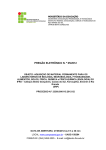
Fig.' 2—Steering G e a r (Sectional V i e w )
HOUSING
H O R N WIRE
57x314 A
STEERING GEAR —7
( 5 ) Remove t w o screws a t t a c h i n g steering j a c k e t
t u b e clamp a t i n s t r u m e n t panel and remove clamp,
( 6 ) Raise t h e carpet t o expose t h e floor
Move r u b b e r g r o m m e t up on j a c k e t column.
panel.
( 7 ) Remove the -screws a t t a c h i n g t h e r u b b e r dust
boot a t t h e dash panel.
( 8 ) Loosen the j a c k e t tube clamp a t t h e steering
gear housing.
( 9 ) Remove the steering a r m n u t and washer a t
t h e steering gear shaft.
( 1 0 ) S i d e t h e Tool 0-3646 up on t h e steering a r m
and place t h e shoe o f t h e p u l l e r behind t h e steering
a r m . T i g h t e n i n g t h e tool center screw against the
gear shaft w i l l p u l l the steering a r m f r o m t h e gear
shaft.
(11) Disconnect t h e h y d r a u l i c b r a k e line a t t h e
master cylinder and b r a k e tee and remove t h e line.
(12) Slide t h e steering gear j a c k e t t u b e r e a r w a r d
and remove i t as an assembly t h r o u g h t h e d r i v e r ' s
compartment.
( 1 3 ) Remove t h e tapered r e t a i n e r and s p r i n g f r o m
t h e column tube ( F i g . 2).
(14) Remove t h e s t e e r i n g gear h o u s i n g to t h e
f r a m e bolts and slide t h e gear t o w a r d t h e rear o f
t h e car and at the same t i m e raise t h e lower end
of t h e gear up.
NUT
( 1 5 ) Remove the s t e e r i n g gear out t h r o u g h t h e
hood opening.
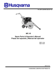
b. Disassembly (Fig. 3)
(1) Remove t h e gear shaft o i l seal f r o m t h e steeri n g h o u s i n g w i t h P u l l e r Tool C-3350. I f t h e shaft is
corroded or d i r t y , clean t h e p o r t i o n between t h e o i l
seal and t h e serrations t o avoid b i n d i n g i n t h e bearings.
N O T E : Position Tool C-3786 gear shaft bearing remover and installer arbor over the gear shaft threads
and while withdrawing the gear shaft, follow with
the arbor. T h i s arbor will keep the bearing rollers
from dropping out of their cages.
(2) Refer t o F i g u r e 3 and remove t h e gear shaft
a d j u s t i n g screw lock n u t , cover gasket and steering
gear shaft assembly.
( 3 ) Remove t h e cover and tube shims, s p r i n g , seal
and washer f r o m the b o t t o m o f t h e housing.
(4) Remove t h e steering tube and w o r m assembly, b e a r i n g cups and bearings, cork, cork r e t a i n e r
and s p r i n g .
( 5 ) I f i t is necessary t o remove t h e h o u s i n g bearings, d r i v e t h e bushings f r o m t h e steering gear
h o u s i n g w i t h t h e gear shaft b e a r i n g r e m o v e r and
i n s t a l l e r arbor, Tool C-3786.
c. Reassembly
Clean a l l p a r t s i n a suitable solvent. Check a l l p a r t s
f o r wear.
SHIMS
~>v
^
_--PLATE
^
-41--"
WASHER^
LOCKWASHER
WORM
GEAR ARM
CAGE AND ROLLERS
SEAL ^
jf
CUP
BUSHINGS—-"""'
HOUSING
'
\
*
.
.
£
^""'4"
SCREW AND
r ''
LOCKWASHER
'
• SPRING
• SEAL
CUP
CONE AND ROLLERS
A
PLUG
SPRING .
SHAFT
SEAL
WASHER
/
RETAINERS
GASKET
i
TUBE
ADJUSTING SCREW"
i
i
1
•
1
LOCK RING59 x 2A
COVER
SCREW AND LOCKWASHER
Fig. 3—Steering G e a r (Disassembled V i e w )
NUT
i
t•
/
8 — STEERING
GEAR
N O T E : Assemble p a r t s w i t h o u t l u b r i c a t i o n . L u b r i cation should be done a f t e r adjustments are completed. Needle bearings are grease-packed
from
factory.
TOOL
I f either o f the w o r m t h r u s t roller bearings are
damaged, replace b o t h bearings. Use new o i l seals.
I f gear shaft bearings have been removed, i n s t a l l
the gear shaft o u t e r b e a r i n g i n t o t h e h o u s i n g w i t h
Tool C-3786 ( F i g . 4 ) . D r i v e t h e outer (lower) beari n g t o w i t h i n 1/16 inch or end o f counterbore. D r i v e
t h e i n n e r (upper) bearing ( F i g . 5) flush w i t h t h e
bore face w i t h Tool C-3786.
( 1 ) I n s e r t the w o r m and t h e tube i n t o t h e h o u s i n g
w i t h bearings and cups.
( 2 ) I n s t a l l shims and lower h o u s i n g cover, m a k i n g
sure bearings are seated.
N O T E : When tightening the cover, turn the worm
tube to be sure no bind exists.
( 3 ) F i n a l t i g h t e n i n g of t h e cover screws should
cause end p l a y t o disappear w i t h torque o f % t o %
pound r e q u i r e d t o r o t a t e t h e tube, w h e n measured
w i t h a p u l l scale applied at t h e r i m of the steering
wheel. A d d or remove shims i n t h e event a b i n d or
excessive end play occurs. Shims are available i n
.003, .006 and .011 inch.
Fig. 5—Installing G e a r Shaft Housing Inner Bearing
end play i n t h e gear shaft is gone. Rotate t h e wheel
t o one end of i t s t r a v e l and apply a s p r i n g scale.
W i t h p u l l applied a t r i m o f t h e steering wheel,
tension should measure f r o m 1 t o 2 pounds. T h e
greatest tension should be f e l t as t h e wheel is r o t a t e d
past the center position ( h i g h p o i n t ) . A d j u s t t h e
t o r q u e load b y t u r n i n g t h e a d j u s t i n g screw i n or out
as r e q u i r e d .
( 8 ) I n s t a l l t h e lock n u t and t i g h t e n w h i l e h o l d i n g
t h e a d j u s t i n g screw.
( 9 ) F i l l the gear housing w i t h S A E 90 gear l u b r i cant and check f o r leaks.
( 4 ) I n s t a l l t h e gear shaft.
( 5 ) Before i n s t a l l i n g the cover, t u r n
screw a l l t h e w a y out.
adjusting
( 6 ) Place s t e e r i n g wheel on tube and r o t a t e
s t e e r i n g wheel i n one d i r e c t i o n t o t h e end o f i t s
t r a v e l . R o t a t e t h e wheel i n t h e o t h e r d i r e c t i o n t o t h e
end o f i t s t r a v e l , c o u n t i n g t h e t u r n s . Rotate t h e
wheel back / o f t h e f u l l n u m b e r o f t u r n s . T h i s is
the exact center of t r a v e l ( h i g h p o i n t ) .
l
2
( 7 ) T u r n t h e a d j u s t i n g screw (clockwise) u n t i l a l l
d. Installation
( 1 ) E n t e r t h e steering gear assembly i n t o t h e
engine c o m p a r t m e n t and t h r o u g h t h e opening i n t h e
floor panel. ~ I n s t a l l t h e h o u s i n g a t t a c h i n g bolts w i t h
t h e " D " bar between t h e f r a m e and the f o r w a r d
m o u n t i n g pad o f the housing (flat o f " D " against
frame, F i g . 6).
( 2 ) I n s t a l l t h e flat washers, spherical washers and
n u t s , b u t do n o t t i g h t e n . Concave side of spherical
STEERING
GEAR
HOUSING
FLAT
TOOL
WASHER
SPHERICAL
SPACER
i f
60 x 17
Fig. 4—iris^cfHrig G e a r Shaft He-using Outer
Bearing
Fig. #—Steering G e a r (Mounting on Frame)
STEERING GEAR —9
washers m u s t be against the steering gear housing.
( 3 ) I n s t a l l t h e b e a r i n g s p r i n g and tapered
t a i n e r on t h e column tube.
re-
( 4 ) Slide t h e j a c k e t tube assembly down against
the shoulder on housing. Raise t h e tube % inch and
t i g h t e n the bolts t o 15 foot-pounds torque.
(5) I n s t a l l the j a c k e t tube bracket clamp at the
i n s t r u m e n t panel. T i g h t e n screw t o 50 inch-pounds
torque.
( 6 ) Connect t h e directional signal wires and the
h o r n w i r e at t h e connectors.
( 7 ) I n s t a l l the t u r n signal s w i t c h ( F i g . 1) and
make sure t h e column j a c k e t does not r e s t r i c t the
s w i t c h movement (on a l l Chrysler models o n l y ) .
( 8 ) I n s t a l l t h e steering wheel and the steering
wheel n u t . T i g h t e n t h e n u t t o 40 foot-pounds torque.
( 9 ) Measure t h e distance between the steering
column j a c k e t tube and the steering wheel, i f , less
t h a n y inch, loosen t h e clamp bolts and adjust t h e
column j a c k e t t o o b t a i n the proper clearance. T i g h t en clamp bolts to 15 foot-pounds torque.
8
StAl
Fig. 7 - R e m o v i n g Gear Shaft Oil Seen
( 3 ) Remove t h e gear shaft o i l seal w i t h Tool
C-3350 gear shaft o i l seal r e m o v i n g and i n s t a l l i n g
tool set as f o l l o w s :
( 4 ) Slide the threaded p o r t i o n o f t h e adapter SP3056 over t h e end o f t h e gear shaft and i n s t a l l t h e
threaded n u t section of the tool on t h e gear shaft.
( 1 0 ) I n s t a l l t h e s t a t i o n a r y plate, bushings, h o r n
r i n g and a t t a c h i n g screws. Connect t h e h o r n w i r e
at the s t a t i o n a r y plate and install the steering wheel
ornament.
(5) Maintain
w i t h t h e n u t of
3056, f o r c i n g i t
metal lip of the
(11) T i g h t e n the j a c k e t tube to the i n s t r u m e n t
panel clamp screws and install the j a c k e t tube dust
shield.
( 6 ) Slide t h e retainer o f Tool C-3350 over the
adapter, engage t h e grooves i n t h e adapter and the
tool n u t w i t h t h e t w o h a l f - r i n g s of t h e tool set and
slide the r e t a i n e r down t o hold t h e h a l f - r i n g s i n position.
( 1 2 ) T i g h t e n f r o n t upper and lower gear housing
t o f r a m e a t t a c h i n g bolts to 20 foot-pounds torque.
( 1 3 ) I n s t a l l a wedge over the r e a r bolt ( F i g . 6)
between the h o u s i n g and the f r a m e so t h a t the
tapered surfaces m a t c h , t a p p i n g i t l i g h t l y i n place
and t i g h t e n t h e three a t t a c h i n g bolts to 50 footpounds torque. T i g h t e n i n g should be done b y alternately t i g h t e n i n g .
( 1 4 ) I n s t a l l steering gear a r m , washer and n u t .
T i g h t e n t o 125 foot-pounds torque.
pressure on the adapter SP-3056
tool, w h i l e t u r n i n g t h e adapter SPi n t o t h e seal u n t i l i t engages t h e
seal.
( 7 ) T u r n i n g t h e p u l l e r n u t counter-clockwise w i l l
p u l l the o i l seal f r o m the housing.
v
TOOL
Ax
%
.
^
'
,. H O U S I N G
Y
- ^ i p i m
( 1 5 ) Reinstall t h e brake line between the master
cylinder and brake tee. Bleed brakes as necessary.
7. GEAR SHAFT O I L SEAL REPLACEMENT
' (Unit i n Vehicle)
a. Removal (Fig. 7)
( 1 ) Remove t h e steering gear a r m n u t .
( 2 ) Remove the steering gear a r m w i t h Puller,
Tool C-3646.
60X803
Fig. 8—Installing Sear Shaft 01 Seal
10 —STEERING GEAR
Bo STEERING GEAR ALIGNMENT
( 1 ) T i g h t e n the body m o u n t i n g bolts a t the f r o n t
f r a m e o u t r i g g e r and the f r o n t frame rear crossmember.
( 2 ) Loosen the steering gear at the frame and
t h e dash support bracket t o allow t h e steering gear
to move i n r e l a t i o n t o t h e frame.
Fig. 9—Idler Arm (Sectional V i e w )
b. Installation (Fig. 8)
( 1 ) Place t h e seal on the seal protector sleeve,
Tool SP-1601 and i n s t a l l the sleeve over t h e splines
on t h e gear shaft ( l i p of seal t o w a r d h o u s i n g ) .
( 2 ) Place the adapter, Tool SP-1934, over t h e p r o tector sleeve and against t h e seal.
( 3 ) T h r e a d t h e tool n u t on the threaded end o f
t h e gear shaft and t u r n t h e tool n u t u n t i l t h e
shoulder o f t h e adapter tool contacts t h e housing.
( 4 ) I n s t a l l t h e steering gear a r m and n u t . T i g h t en the nuts to 125 foot-pounds torque.
N O T E : Make sure the pivot ("D") bar at the front
end of the steering gear housing is between the
housing and the frame with the flat side of the bar
against the frame and the concave side of the
spherical washers must be against the housing
(Fig. 6 ) .
( 3 ) T i g h t e n the t w o f r o n t m o u n t i n g bolt n u t s
finger t i g h t and j u s t s t a r t t h e rear m o u n t i n g bolt
n u t on t h e threads.
(4) T i g h t e n t h e j a c k e t tube clamp at the gear
housing t o 15 foot-pounds torque.
( 5 ) Position t h e steering column j a c k e t tube i n
t h e i n s t r u m e n t panel j a c k e t support and t i g h t e n
t h e screw t o 50 inch-pounds torque.
(6) I n s t a l l t h e wedge between t h e steering gear
housing and frame at t h e rear m o u n t i n g bolt, so t h a t
t h e tapered surface o f t h e wedge matches w i t h t h e
taper o f housing.
STEERING GEAR—-11
( 7 ) T i g h t e n t h e steering gear housing t o frame
bolts t o 50 foot-pounds torque,
C R E A S E CAP
THRUST WASHER
STEERING KNUCKLE
NUT
SEA!
N O T E : T i g h t e n i n g should be done b y a l t e r n a t e l y
t i g h t e n i n g the r e a r a n d f r o n t m o u n t i n g b o l t s g r a d u a l l y so t h a t gear a l i g n m e n t is n o t d i s t u r b e d .
Adjustments ©f the H o l e r Tooth and W o r n
(In Vehicle)
•••••
( 1 ) Disconnect t h e steering gear a r m a t t h e l i n k .
mm. /m ^^^^^^m
]
( 2 ) Rotate t h e steering wheel t o m i d - p o s i t i o n and
t h e n check f o r backlash b y a t t e m p t i n g t o move t h e
steering gear a r m back and f o r t h .
( 3 ) I f backlash exists, loosen t h e gear shaft adj u s t m e n t screw lock n u t and t i g h t e n t h e a d j u s t i n g
screw enough t o eliminate free play. B e sure t h e
r o l l e r shaft and t h e w o r m do n o t b i n d . Recheck backlash.
( 4 ) T i g h t e n t h e a d j u s t i n g screw lock n u t w h i l e
h o l d i n g t h e a d j u s t i n g screw f r o m t u r n i n g .
( 5 ) I n s t a l l t h e steering gear a r m .
S. REMOVAL A N D REPLACEMENT O F THE
IDLER A R M (Fig. 9)
( 1 ) Place t h e f r o n t wheels i n t h e straight-ahead
position.
( 2 ) Remove t h e cotter p i n and n u t and separate
t h e l i n k and t h e a r m .
(3) Remove t h e cotter p i n , n u t a n d t h e m o u n t i n g
bolt a n d slide t h e i d l e r a r m o u t o f t h e bracket. T i e
NUT LOCK
COTTERPIN
B E A R I N G CUP
BEARING C O N E
BEARING CONE
57x309
Fig. 12—Front Wheel Bearing Adjustment
idler a r m a n d b u s h i n g are serviced only i n a n assembly.
( 4 ) Measure t h e w i d t h o f t h e i d l e r bracket. T h e
distance between t h e b u s h i n g contact surfaces should
be 214 inches ( F i g . 1 0 ) .
( 5 ) I n s t a l l t h e i d l e r a r m (protect b u s h i n g ends
f r o m being damaged f r o m t h e sharp edges o f t h e
m o u n t i n g b o l t holes b y using a s h i m stock over t h e
holes).
( 6 ) Coat t h e m o u n t i n g b o l t w i t h l u b r i p l a t e and
slide t h e bolt t h r o u g h t h e bracket and b u s h i n g ; i n stall the nut.
( 7 ) W i t h t h e wheels i n t h e straight-ahead posit i o n , t i g h t e n t h e n u t t o 85 foot-pounds t o r q u e ; install
t h e cotter p i n .
10. STEERING KNUCKLE TIE RODS
a. Removal
N O T E : T h e t i e r o d end and 'bolt i s serviced o n l y as
a n assembly.
mi-Mi',i W A S H ; IN-
( 1 ) Loosen t h e n u t on t h e r o d end and remove t h e
t i e r o d end w i t h Tool C-3394.
( 2 ) I n s e r t t h e l e g o f t h e tool between t h e steering
linkage knuckle a r m and t h e t i e r o d end.
I 'I I!
( 3 ) T u r n t h e p u l l e r screw against t h e t i e r o d end
n u t , f o r c i n g t h e t i e r o d end f r o m t h e knuckle a r m .
\(
( 4 ) Remove t h e t i e r o d f r o m center l i n k b y placing
leg o f puller between center l i n k a n d t i e r o d end.
( M i l l l.'Ml I
Fig. 11— Positioning Bearing N u t Lock
( 5 ) Remove, t h e t i e r o d - e n d assembly f r o m t h e
t i e r o d b y loosening t h e clamps and unscrewing t h e
r o d end assembly.
(1) W h e n i n s t a l l i n g t h e t i e r o d ends t o t h e r o d
tube, be sure t o t h r e a d t h e ends evenly on tube body
12 —STEERING GEAR
t o the n o m i n a l l e n g t h to obtain proper positioning of
t h e steering wheel.
N O T E : The clamping bolts m u s t be beneath t h e t i e
rods t o prevent interference on t u r n s . Measure and
adjust the toe-in w h e n the new t i e rods are installed.
a. Adjusting
N O T E ; I t is i m p o r t a n t to remove any b u r r s or nicks
on the spindle t h r e a d to insure accurate torque reading.
( 1 ) T i g h t e n the wheel bearing a d j u s t i n g n u t t o
180 inch-pounds w h i l e r o t a t i n g the wheel.
( 2 ) Position t h e n u t lock on the n u t w i t h one p a i r
of slots i n line w i t h the cotter p i n hole.
2
( 1 ) Remove the d r u m and remove the inner o i l
seal and bearing ( F i g . 1 2 ) . I n v e r t the d r u m , t h e n
using a suitable d r i f t , drive t h e outer bearing race
f r o m the d r u m . ( D r i v i n g slots are machined i n the
d r u m f o r t h i s operation).
( 2 ) A g a i n i n v e r t the d r u m and d r i v e out the i n ner bearing race.
11. F I O N T WHEEL BEAMINGS (Fig. I I )
( 3 ) Back off the a d j u s t i n g n u t iy
cotter p i n hole w i l l be covered.)
b. Removing Front Wheel Bearing l a c e s
slots.
(The
( 4 ) Remove t h e lock and re-position i t so t h e cott e r p i n can be inserted. Do n o t move the a d j u s t i n g
nut.
( 5 ) I n s t a l l t h e cotter p i n .
( 3 ) Clean the d r u m and bearings, using a suitable
solvent, t h e n blow d r y w i t h compressed air. ( D o n o t
spin bearings w i t h a i r pressure.) Check the bearings
f o r pits or brinelling. I n s t a l l new bearings as required.
c. Installation of Front W h e e l Bearing l a c e s
W h e n i n s t a l l i n g new bearing races, be sure to s t a r t
t h e race evenly i n the d r u m . D r i v e down i n t o posit i o n alternately, using ( i f possible) the old race. Be
sure the race is seated evenly.
Pack the inner bearing w i t h short fibre grease,
t h e n i n s t a l l i n the d r u m . I n s t a l l new grease seal.
Slide the d r u m over spindle and i n t o the d r u m .
I n s t a l l a t h r u s t washer and n u t , t h e n adjust t h e beari n g as described i n Paragraph 11 ( a ) .
CONSTANT CONTROL
FULL TIME
POWER STEERING
SERVICE DIAGNOSIS
2. Pressure control valve stuck i n closed position.
12. HARD STEERING
a.
T i r e s not properly inflated.
3. Defective or damaged valve lever.
b. L o w o i l level (usually accompanied b y p u m p
noise).
4.
c. Loose p u m p belt.
d.
O i l on p u m p belts.
e.
Steering linkage needs l u b r i c a t i o n .
c. Sector shaft cover " 0 " r i n g seal.
d. Valve housing-to-gear housing " 0 " r i n g .
Gear shaft a d j u s t m e n t t o t i g h t .
g r a p h 21.)
5. Excessive i n t e r n a l leakage.
13. POOR R E C O V E R Y F R O M TURNS
Steering gear m a l f u n c t i o n .
1.
L o w e r sector shaft o i l seal.
b. Sector shaft a d j u s t i n g screw seal.
f. Power steering p u m p o u t p u t low. See Parag r a p h 20 — "Pressure Test."
g.
E x t e r n a l oil leakage at t h e f o l l o w i n g p o i n t s :
-a.
(See Para-
a.
T i r e s not properly inflated.
b.
Steering linkage b i n d i n g .
STEERING GEAR—13
c. I m p r o p e r wheel alignment.
d.
h.
1.
Damaged or f a u l t y steering tube bearing.
I m p r o p e r gear shaft
(See P a r a g r a p h 21.)
mesh
adjustment.
2. Pressure control valve piston stuck i n open
position.
3. Column support spanner n u t loose.
worm
thrust
bearing
adjust-
cylinder head w o r m
8. D i r t or chips i n steering gear u n i t .
9. Rough or catchy w o r m i n t h e piston assembly.
10.
(See
16. EXCESSIVE STEERING WHEEL FREE-PLAY
a. I m p r o p e r gear shaft adjustment.
graph 21.)
b.
(See Para-
Column support spanner n u t loose.
d.
Coupling loose on t h e w o r m shaft.
17. LACK O F ASSISTANCE (One Direction)
6. B u r r s or nicks i n reaction r i n g grooves i n
cylinder head or column support.
7. F a u l t y or damaged
seal r i n g .
adjustment.
c. I m p r o p e r w o r m t h r u s t bearing adjustment.
4. F a u l t y or damaged valve lever.
5. I m p r o p e r
ment.
shaft
3. Excessive i n t e r n a l leakage.
Steering gear malfunctions.
1.
E x t e r n a l leakage.
2. I m p r o p e r gear
P a r a g r a p h 21.)
e. Steering wheel column j a c k e t and steering u n i t
not properly aligned.
f.
Gear malfunctions.
F a u l t y w o r m piston r i n g .
14. SELF-STEERING OR LEADS TO EITHER SIDE
a. Oil leaking past w o r m shaft oil seal r i n g or
throttle " 0 " ring.
b.
B r o k e n or w o r n r i n g on w o r m piston.
c. Piston end p l u g loose.
d. Reaction seal missing.
(Both Directions)
a.
P u m p belt slipping.
b. P u m p o u t p u t low.
a.
Tires not properly inflated.
c. B r o k e n or w o r n r i n g on w o r m piston.
b.
I m p r o p e r wheel alignment.
do
Piston end p l u g loose.
e.
Reaction seal missing.
f.
I n t e r n a l leakage i n the valve body.
c. Steering wheel off center w h e n the car is t r a v e l i n g s t r a i g h t ahead.
d. V a l v e body out of a d j u s t m e n t :
Steering to the left — Move t h e steering valve
housing down on the steering housing.
18. NOISES
a. Buzzing noise i n n e u t r a l , stops w h e n the steeri n g wheel is t u r n e d .
Steering to the r i g h t — Move the steering housing
up on the steering housing.
1.
N o i s y pump.
2. Damaged h y d r a u l i c lines.
e.
Valve lever damaged.
f.
Column support spanner n u t loose.
15. TEMPORARY INCREASES I N EFFORT W H E N
TURNING STEERING WHEEL TO RIGHT OR LEFT
a.
Oil level low.
3. Pressure control valve s t i c k i n g .
4. A i r i n system.
b.
C h u c k l i n g noise.
1.
I m p r o p e r gear
P a r a g r a p h 21.)
shaft
adjustment.
(See
b. Loose p u m p belt.
2. I m p r o p e r w o r m t h r u s t bearing adjustment.
c. Oil on p u m p belts.
d.
B i n d i n g steering linkage.
3. Excessive r a d i a l clearance i n t h e column
j a c k e t support bearing.
e.
Engine idle too slow.
4.
f.
F a u l t y power steering pump.
g. A i r i n system. ( W o r k t h e steering wheel f r o m
r i g h t to left u n t i l t h e a i r is expelled.)
Coupling loose on t h e w o r m shaft.
c. Metallic clatter or t a p p i n g noise.
1.
Back pressure valve cushion m i s s i n g or
broken.
OIL
BY-PASS RELIEF
LEFT TURN POWER
PASSAGE
CHAMBER
\
SPOOL
VALVE
OIL O U T L E T
B A C K - P R E S S U R E V A L V E AND SPRING
RECIRCULATING B A L L CIRCUIT
POWER
PISTON
STEERING SHAFT
CROSS SHAFT
SECTOR GEAR
F L E X I B L E COUPLING -~
COLUMN JACKET SUPPORT
—
—
WORM SHAFT BALANCING RING —
^
—
L E F T TURN R E A C T I O N RING -
STEERING GEAR
C R O S S SHAFT
CENTER THRUST BEARING RACE
RIGHT TURN REACTION RING - - CYLINDER H E A D
WORM SHAFT ~~~~
RIGHT TURN POWER CHAMBER
FRAME SIDE RAIL
-
—
'
STEERING A R M
ADJUSTING
WEDGE
6Qx.11
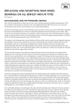
Fig. 13—Power Steering Complete (Cross Section)
STEERING GEAR—15
POWER STEERING
19. DESCRIPTION A N D OPERATION
TO RESERVOIR
4
a. Description
PUMP
PRESSURE IN
The power steering gear ( F i g s . 13 a n d 14) consists
of a gear housing containing a gear shaft w i t h
sector gear, a power p i s t o n w i t h gear teeth milled
i n t o t h e side of the p i s t o n is i n constant mesh w i t h
t h e gear shaft sector and a w o r m s h a f t connects t h e
steering wheel t o t h e power piston. The w o r m shaft
is geared t o the piston t h r o u g h a r e c i r c u l a t i n g ball
contact.
b. Operation
I n t h i s explanation o f operation (as viewed i n t h e
f o l l o w i n g i l l u s t r a t i o n s ) the l e f t end of t h e steering
gear means the lower end and t h e r i g h t end means
the upper end o f t h e steering gear. D i r e c t i o n of o i l
flow w i l l also be described as flowing t o left or r i g h t
as shown i n the f o l l o w i n g i l l u s t r a t i o n s .
W h e n t h e car is i n t h e straight-ahead direction,
the steering valve is i n t h e n e u t r a l (center) position
and o i l flow t h r o u g h b o t h of t h e grooves i n t h e
steering valve body is equal, since i n t h e n e u t r a l
position ( F i g . 15), the t w o lands o f t h e steering valve
are centered i n t h e grooves of the valve body. The
left oil passage directs i t s oil where i t contacts t h e
r i g h t (upper) end o f t h e power p i s t o n and across
i n t o the r i g h t reaction chamber. P a r t o f t h i s o i l is
forced around the grooves o f t h e w o r m shaft, inside
t h e piston and around t h e r e c i r c u l a t i n g balls, t o
the hollow area between t h e left ( l o w e r ) end of t h e
w o r m shaft and t h e l e f t (lower) end o f the power
piston. Pressure on t h e end of t h e w o r m shaft is
balanced b y the pressure against t h e area o f the
w o r m shaft balancing r i n g .
A t t h e same t i m e , oil f r o m the r i g h t groove i n t h e
steering valve is directed t o the left, t h r o u g h a gallery, parallel t o t h e w o r m shaft. T h i s o i l flows t o t h e
CROSS S H A F T
SECTOR GFAR
=>i'WER !- iSTON
58X198A
Fig. 14—Steering G e a r Housing (Sectional V i e w )
f
TO PISTON
58X200A
Fig. 15—Steering G e a r V a l v e (Neutral Position)
area below the power p i s t o n flange. P a r t of t h i s o i l
is t h e n directed t h r o u g h the cylinder head i n t o t h e
left reaction chamber.
Forces exerted on t h e piston t h r o u g h oil pressure
on i t s faces are completely balanced b y the t w o
reaction r i n g s shown i n cross section i n F i g u r e 16.
The reaction r i n g shown to t h e left o f t h e center
b e a r i n g race is fed o i l f r o m the r i g h t t u r n power
chamber o i l g a l l e r y t h r o u g h a drilled hole.
W h e n t h e d r i v e r makes a left t u r n , power is i m mediately provided b y t h e u n i t to effect t h e t u r n .
A s t h e w o r m s h a f t rotates inside t h e power piston,
the p i s t o n is prevented f r o m i n s t a n t l y " c l i m b i n g
d o w n " t h e w o r m s h a f t b y t h e resisting forces w h i c h
the steering linkage and wheels t r a n s m i t t o t h e
steering gear cross shaft. Instead, the w o r m shaft
is " d r a w n o u t " o f t h e piston a v e r y small a m o u n t
(a few thousandths o f an i n c h ) . The center t h r u s t
bearing race, w h i c h i n effect is clamped a x i a l l y t o
t h e w o r m s h a f t , moves the same distance. T h e race
t h u s t i p s t h e p i v o t lever and moves t h e steering
valve t o t h e left ( d o w n ) .
The o i l flow d i a g r a m f o r a left t u r n is shown i n
F i g u r e 17. Here i t can be seen t h a t as t h e left edges
of t h e t w o lands on the valve approach t h e groove
edges o f t h e valve body, t w o t h i n g s happen: F l o w
t o t h e r i g h t groove i n t h e valve body is reduced and
t h e flow of o i l t o the l e f t groove is increased because
the opening is larger. O i l t h e n flows f r o m the power
16 —STEERING GEAR
steering pump t h r o u g h the enlarged orifice and
t h r o u g h t h e o i l gallery t o the left t u r n power chamber of t h e piston ( F i g . 1 8 ) . Since the supply of o i l t o
the left (lower side) ( r i g h t t u r n chamber) of t h e pist o n has been cut off b y movement of the steering
valve, a force o f unbalance on t h e p i s t o n exists and
i t is pushed t o the left. I t s linear movement is t r a n s lated i n t o r o t a t i o n of the cross shaft sector gear
(Figs. 13 and 14) and subsequently t h r o u g h the
steering linkage t o the f r o n t wheels.
I n t h e reaction area of t h e steering u n i t another
action takes place simultaneously as the wheel is
t u r n e d to the left. The r e s t r a i n i n g force of the react i o n s p r i n g m u s t be overcome before t h e center race
can move t o t h e r i g h t . , The force o f t h e reaction
s p r i n g provides positive r e t u r n a b i l i t y t o t h e u n i t . A t
t h e i n s t a n t w h e n power assistance is no longer desired b y the d r i v e r , t h e reaction s p r i n g and t h e opera t i n g o i l pressure move the center t h r u s t bearing
race and t h e steering spool valve back t o t h e i r neut r a l (center) positions. E q u a l o i l pressures t h e n are
directed to b o t h sides of the pow er piston and power
assist ceases immediately. The n a t u r a l effect of the
f r o n t wheel caster and the steering axis i n c l i n a t i o n
then r e t u r n s the wheels to t h e i r straight-ahead
position.
T
W h e n a r i g h t t u r n is made, a l l of the earlier described actions necessary t o make a left t u r n i n the
steering u n i t are repeated, except t h a t all of the
motions are reversed. Consequently, i n a r i g h t t u r n ,
STEERING GEAR—17
TO RESERVOIR
i
r e t u r n the center t h r u s t bearing race to i t s n e u t r a l
position. The d r i v e r feels t h i s force on the reaction
r i n g s (shown i n F i g u r e s 17 and 18) as a force p r o portional to operating oil pressure. I t causes the
d r i v e r to exert a steering effort p r o p o r t i o n a l t o t h e
t o t a l force required to t u r n the f r o n t wheels of the
car. The force he actually exerts Is only a small percentage o f t h e ' t o t a l force t h a t would be r e q u i r e d
to steer the car w i t h a m a n u a l gear. I f o i l pressure
is I n t e r r u p t e d i n t h e steering gear, I t w o u l d operate
w i t h increased effort and there would be more steeri n g wheel free play. However, complete steering
control is retained by the d r i v e r i f a "lack of power
assist" condition should ever arise.
PUMP
20. PBESSU1E TEST (STEERING GEAR A N D PUMP)
Fig. 17—Steering Gear V a l v e (Left Turn Position)
the lower side of the power piston and the r i g h t t u r n
reaction r i n g are pressurized ( F i g . 1 8 ) .
The force o f t h i s reaction s p r i n g also contributes
to increased on-center "feel." The " f e e l " Is f u r t h e r
provided b y the operating oil pressure w h i c h tends t o
( 1 ) S t a r t t h e engine, t u r n the steering wheel a l l
the w a y t o t h e left and back all t h e w a y to the r i g h t
several t i m e s t o expel a i r f r o m the system, t h e n shut
off the engine.
( 2 ) Remove the filler cap and v i s u a l l y check t h e
oil level i n the reservoirs.
Engine Cold—Oil level should be at the b o t t o m
of the filler neck.
Engine H o t — O i l level should be one-half w a y up
i n the filler neck.
TO RESERVOIR
4
PUMP
Fig. 18—Oil F l o w (Left Turn Position)
18 — S T E E R I N G G E A R
I f necessary, add only M o p a r N o . 2084329 Power
Steering F l u i d to b r i n g up t o the required level. Do
not overfill.
(3) Check the p u m p belt tension.
(4) Disconnect the p u m p to t h e steering gear
pressure hose a t the power steering pump. Connect
the test hose Tool C-3388 w i t h t h e proper adapters
between t h e power steering pump and the pressure
gauge Tool C-3309B w i t h the shut-off valve between
the pressure gauge and the pressure hose t h a t y o u
disconnected f r o m the p u m p ( F i g . 1 9 ) . Make sure
all connections are t i g h t and t h a t the shut-off valve is
f u l l y opened.
( 5 ) S t a r t t h e engine and operate at idle speed
(500 r p m ) .
Fig.
2 0 - J a c k e t Tube installation ( P C - 1 ,
2,
3
and P Y - 1 )
( 6 ) W i t h the engine operating at idle (500 r p m )
and o i l temperature between 150 degrees F . and 170
degrees F . (checked w i t h thermometer i n the reserv o i r ) the pressure gauge should show a pressure of
55 t o 80 psi. I f the pressure is higher, check t h e
hoses and connections f o r k i n k s and obstructions,
check the p u m p or flow c o n t r o l valve f o r f a u l t y
operation.
psi, the relief valve is f a u l t y or the pump is equipped
w i t h the w r o n g relief valve.
( 7 ) Increase the engine speed t o 1000 r p m , t h e n
slowly close the gauge shut-off valve. The p u m p
pressure should be 950 t o 1150 psi w i t h the gauge
shut-off valve f u l l y closed.
d. Open the gauge shut-off valve and operate t h e
steering u n i t t h r o u g h another cycle, t h i s t i m e holdi n g u n i t at extreme t r a v e l i n each direction while
w a t c h i n g the o i l pressure gauge. The gauge reading
should be equal i n each direction. I f not, i t indicates
excessive i n t e r n a l leakage i n the u n i t . D o n o t hold
t h e w o r m s h a f t at either extreme position f o r more
t h a n a few seconds.
CAUTION
Do n o t close the valve f o r more t h a n a few seconds,
as t h i s would a b n o r m a l l y increase the o i l temperature and cause undue o i l p u m p wear.
a.
I f t h e pressure increases t o more t h a n 1050
b. I f the pressure is less t h a n 950 psi, the p u m p
is f a u l t y .
c. I f t h e pressure is w i t h i n the specified range o f
950 to 1050 psi, the p u m p is operating properly and
t h e trouble is i n the steering gear.
21. GEAR SHAFT ADJUSTMENT
(1) W i t h the gear shaft on center, loosen gear
shaft a d j u s t i n g screw lock n u t ] / t u r n and t i g h t e n
t h e a d j u s t i n g screw u n t i l backlash j u s t disappears.
T i g h t e n screw 1 % t u r n s f r o m t h i s position and w h i l e
h o l d i n g the a d j u s t i n g screw i n t h i s position, t i g h t e n
t h e lock n u t .
2
N O T E : T h i s is a t e m p o r a r y adjustment t o insure
t h a t the piston rack and sector t e e t h are i n f u l l alignment.
(2) Operate u n i t m a n u a l l y f o r a m i n i m u m o f 180
degrees f r o m the center i n each direction, measured
at w o r m shaft.
Fig.
1 9 — P r e s s u r e Testing Pump a n d Steering G e a r
( 3 ) S t a r t the engine and r u n at idle speed. W i t h
h y d r a u l i c power to t h e steering gear u n i t and w i t h
t h e gear shaft on center plus o r minus 2 degrees,
readjust the gear shaft backlash. T h i s w i l l require
loosening the a d j u s t i n g screw u n t i l the backlash is
STEERING GEAR—19
(12) Loosen t h e j a c k e t tube clamp at t h e steeri n g gear housing.
(13) Remove the cotter key and n u t a t t h e d r a g
l i n k and disconnect t h e l i n k f r o m the steering a r m .
(14) Remove t h e steering a r m n u t and washer at
t h e steering gear shaft.
(15) Slide Tool C-3646 up on t h e steering a r m and
place the shoe o f t h e puller behind the steering a r m
( F i g . 2 2 ) . T i g h t e n i n g t h e tool center screw against
t h e gear shaft, w i l l p u l l t h e steering a r m f r o m t h e
gear shaft.
CAUTION
Fig. 2 1 - J a c k e t Tube installation (PS-1 and PS-3)
Do not remove the steering a r m by prying with a
lever or striking with a hammer as serious steering
gear internal damage will result.
evident. R e t i g h t e n the a d j u s t i n g screw u n t i l the
backlash j u s t disappears. Continue t o t i g h t e n % t o
/ t u r n f r o m t h i s position and t i g h t e n t h e lock n u t
50 foot-pounds torque to m a i n t a i n t h i s s e t t i n g .
(16) Disconnect the h y d r a u l i c brake line at the
master cylinder and t h e brake tee and remove the
line ( n o t necessary on I m p e r i a l cars).
l
2
22. REMOVING POWER STEERING GEAR UNIT
(1)
Disconnect the b a t t e r y g r o u n d cable.
( 2 ) Remove the steering wheel ornament by
pressing d o w n on center ornament and t u r n i n g the
ornament / t u r n t o remove.
l
4
( 3 ) Disconnect t h e h o r n w i r e and remove three
screws, bushings, h o r n b l o w i n g r i n g , rubber i n s u l a t o r
and h o r n t e r m i n a l plate.
(4) Disconnect t h e directional signal w i r e s and the
h o r n w i r e at connectors.
( 5 ) Loosen the steering wheel n u t t h r e e t u r n s .
Use puller, Tool C-3428, to loosen steering wheel.
( 6 ) Remove the tool, steering wheel n u t and steeri n g wheel.
( 7 ) Remove t h e directional s w i t c h
mechanism ( F i g . 1, M a n u a l S t e e r i n g ) .
(17) Disconnect the pressure and r e t u r n hoses
at t h e steering gear. Fasten t h e ends of t h e hoses
above the o i l level i n reservoir. Cap the ends of the
hoses. Cap t h e fittings on t h e steering gear.
(18) Slide t h e j a c k e t tube up and off the steering
gear t h r o u g h the d r i v e r ' s compartment. Remove the
j a c k e t tube upper s p r i n g a n d retainer. Remove the
rubber insulator boot and h o r n ground strap (copper) .
(19) Remove t h e steering tube coupling p i n , t w o
plastic inserts, h o r n ground strap (copper) ( F i g . 2 3 ) ,
rubber i n s u l a t o r and upper steering tube.
(20) Remove t h e gear housing to frame bolts,
washers and a l i g n m e n t wedge. Slide the steering
gear towards t h e rear o f t h e car and at t h e same
cancelling
*:**
:J
STEERING GEAR
( 8 ) Remove t h e retainer snap r i n g ( F i g s . 20 and
21) f r o m the groove i n t h e steering tube at t h e top
of t h e bearing using pliers Tool C-3229.
( 9 ) Remove t h e j a c k e t tube shield t o allow access
to the column tube clamp and remove t h e screws
a t t a c h i n g the steering j a c k e t tube clamp a t the
i n s t r u m e n t panel and remove t h e clamp.
(10) Raise the carpet to expose t h e floor panel.
Move t h e rubber g r o m m e t up. on the j a c k e t column.
(11) Remove the screws a t t a c h i n g t h e rubber
dust boot at f i r e w a l l . (On I m p e r i a l cars, remove t h e
floor inspection panel.)
^^^^
Fig. 22—Removing Steering G e a r A r m
58x231
20 — S T E E R I N G G E A R
COLUMN
SUPPORT
G R O U N D STRIP (IF S O EQUIPPED)
-CLAMP
S E A L (IF S O EQUIPPED)
COLUMN TUBE
INSULATOR
G R O U N D STRIP
(IF S O EQUIPPED)
INSERT
2
PLASTIC ( 2 )
STEERING TUBE
INSULATOR
60x19
Fig.
2 3 — J a c k e t Tube a n d Column Tube (Cross Section)
t i m e , raise the lower end of the gear to remove the
gear at t h e engine c o m p a r t m n t . (Remove t h e gear
t h r o u g h the d r i v e r ' s c o m p a r t m e n t on I m p e r i a l cars.)
(21) On cars equipped w i t h R a m M a n i f o l d , remove t h e fender inspection opening panel. Raise
t h e lower end o f t h e gear housing and r o t a t e t h e
assembly i n a clockwise m o t i o n towards the cowl
panel u n t i l the gear shaft splines clear t h e f r a m e
r a i l , t h e n t i l t the housing t o w a r d t h e engine and
remove t h e steering gear assembly (gear shaft end
first) t h r o u g h inspection hole at fender side panel.
23* DISASSEMBLY OF STEERING GEAR (Fig. 13)
N O T E : P r i o r to disassembly, clean the gear assembly
t h o r o u g h l y i n a suitable solvent and i n s t a l l t h e u n i t
i n t h e h o l d i n g fixture C-3323 ( F i g . 2 4 ) .
W h e n disassembling, each p a r t should be placed
i n a suitable solvent, washed, t h e n d r i e d b y d r y
compressed a i r . Careful h a n d l i n g of the parts m u s t
be exercised t o avoid t h e occurrence of nicks and
b u r r s . Crocus cloth m a y be used t o remove small
nicks or b u r r s provided i t is used carefully. W h e n
used on t h e steering gear valve, use extreme care
not to r o u n d off t h e sharp edge portions o f the t w o
lands located between t h e valve drilled holes. The
sharp edge p o r t i o n of these t w o lands is v i t a l l y i m p o r t a n t to t h i s t y p e of valve.
Remove and discard a l l " 0 " seal r i n g s and seals.
Use new ones lubricated w i t h p e t r o l a t u m w h e n reassembling.
(1) D r a i n the steering gear t h r o u g h t h e pressure
and r e t u r n connections b y t u r n i n g the steering tube
coupling f r o m one extreme of t r a v e l t o t h e other.
(2) A l i g n the coupling p i n w i t h the holes i n
steering column j a c k e t support and remove the
coupling p i n ( F i g . 2 4 ) .
CAUTION
Support the coupling when d r i v i n g the p i n i n o r out
to avoid d a m a g i n g the w o r m shaft and bearings.
( 3 ) Remove the valve body housing a t t a c h i n g
screws and remove the valve body and the three " 0 "
rings (Fig. 25).
( 4 ) Remove the valve lever and s p r i n g . P r y under
the spherical head w i t h a screwdriver. Use care n o t
to collapse the slotted end of the valve lever as t h i s
w i l l destroy t h e bearing tolerances of t h e spherical
head.
(5) Loosen t h e gear shaft a d j u s t i n g screw locknut to f a c i l i t a t e removal and remove the gear shaft
cover n u t w i t h Tool C-3633 ( F i g . 2 6 ) .
CAUTION
O i l w i l l be expelled w h e n t h e gear shaft and cover
are w i t h d r a w n f r o m the housing.
VALVE
-
ASSEMBLY
' *
*ji
4-
24—Removing Coupling Pin
"O
Fig.
LEVER
/
J
jpp"
58x64
Fig.
r
VALVE
•
1
M
RINGS
58x34
25—Removing or Installing V a l v e Body A s s e m b l y
STEERING GEAR
(6) Rotate the w o r m shaft to the f u l l r i g h t t u r n
position, t h e n r e t u r n the w o r m shaft to the center of
t r a v e l . T h i s w i l l place the p i s t o n i n the center posit i o n ( F i g . 1 4 ) . W i t h d r a w the gear shaft u n t i l the
sector teeth clear t h e housing. Rotate t h e shaft 180
degrees and allow the ends o f t h e teeth to rest on
t h e housing.
(8) Remove the steering j a c k e t support n u t w i t h
ToolC-3634 ( F i g . 2 7 ) .
( 9 ) F i r m l y i n s t a l l a suitable d r i f t t h r o u g h the
hole i n the j a c k e t support t o engage t h e groove i n
the w o r m shaft, thereby l o c k i n g these t w o p a r t s t o gether ( F i g . 2 8 ) .
(10) W h i l e h o l d i n g the d r i f t , p r y on t h e piston
teeth w i t h a s c r e w d r i v e r u s i n g t h e gear shaft as a
f u l c r u m and remove the complete p o w e r t r a i n .
N O T E : B y t h i s procedure, the w o r m will be all the
way i n t o the p i s t o n and the power t r a i n p a r t s will be
r e s t i n g against t h e piston flange. I t is i m p e r a t i v e
t h a t the cylinder head, center race and spacer assembly and t h e j a c k e t support be m a i n t a i n e d in close
contact w i t h each other. T h i s will p r o h i b i t t h e teflon
sealing r i n g on the w o r m shaft f r o m becoming disengaged f r o m i t s m a t i n g sleeve retained in t h e c y l i n der head. I t w i l l also eliminate t h e possibility of the
reaction r i n g s becoming disengaged f r o m t h e i r
grooves in b o t h the cylinder head and column j a c k e t
support.
(11) Remove the gear shaft assembly f r o m the
housing and remove t h e steering gear h o u s i n g f r o m
t h e vise.
24.
SPANNER NUT
1
58x38
Nut
Fig. 27—Removing Steering Coiumro S y p
soft j a w s to avoid damaging t h e p i s t o n assembly.
CAUTION
Do n o t t u r n t h e w o r m shaft more t h a n one-half t u r n
d u r i n g disassembly.
(2) Remove the column j a c k e t support t a n g washer and j a c k e t support.
( 3 ) Remove the reaction s p r i n g , reaction r i n g and
spacer, f e r r u l e " 0 " r i n g and the center b e a r i n g
spacer.
( 4 ) H o l d t h e w o r m shaft f r o m t u r n i n g , t h e n
t u r n the n u t w i t h sufficient force t o release the
staked portions f r o m the k n u r l e d section and remove
the nut.
N O T E : W i r e b r u s h the k n u r l e d section t o remove
chips, t h e n blow o u t the n u t and w o r m s h a f t t o
remove any m e t a l particles.
(5) Remove t h e upper t h r u s t bearing race ( t h i n )
and upper t h r u s t bearing.
(6) Remove t h e center b e a r i n g race.
(7) Remove the lower t h r u s t b e a r i n g and lower
t h r u s t b e a r i n g race ( t h i c k ) .
DISASSEMBLY OF POWER TRAIN
(1)
r y
TOOL-
(7) T u r n the w o r m shaft t o f u l l r i g h t t u r n posit i o n to compress the p o w e r t r a i n p a r t s and t h e n
remove the c o u p l i n g .
—21
Place the power t r a i n i n a vise equipped w i t h
( 8 ) Remove t h e lower reaction r i n g and reaction
spring.
TOOL
POWER TRAIN
H O L D I N G FIXTURE
J A C K E T TUBE SUPPORT
^
^.y
a
*4
j ^
J A C K E T TUBE SUPPORT
5 8 x 3 6
Fig. 26—Removing or Installing G e a r Shaft Cover Nut
Fig.
50x39
28—Removing or Installing Power Train
22 —• STEERING GEAR
STEERING GEAR HOUSING
IACKLV TU3E SUPPORT
OIL SEAL
root.
''
J A C K E T T U B I:
W SUPPORT
*TOOl
/
-/
MM
SEAL
-y^^^^^m
58x40
L%
Fig. 29—Removing Worm Shaft Upper Seat
e
"""^ SPANNER NUT
58x44
SI—Installing Worm Shaft Upper Seal
Tool C-3650 ( F i g . 31) ( w i t h the l i p o f the seal t o w a r d
bearing).
( i ) Remove t h e cylinder head assembly.
N O T E : T h e w o r m and p i s t o n assembly i s f u r n i s h e d
as a complete assembly o n l y .
( 2 ) L u b r i c a t e and i n s t a l l t h e reaction seal i n the
groove i n t h e face of the column j a c k e t support w i t h
t h e flat side o f t h e seal o u t ( F i g . 3 2 ) .
25. C O L U M N JACKET SUPPORT
a.
28. CYLINDER HEAD
Disassembly
( 1 ) Remove t h e w o r m shaft upper seal w i t h puller
Tool C-3638 ( F i g . 2 9 ) .
N O T E : The column j a c k e t support and w o r m s h a f t
upper bearing are serviced as a n assembly.
a.
Disassembly
( 1 ) Remove the t w o " 0 " r i n g s i n the t w o outer
grooves i n the cylinder head.
( 2 ) Remove t h e large " 0 " r i n g f r o m t h e groove
i n t h e j a c k e t support.
( 2 ) Remove the lower reaction " 0 " r i n g i n t h e
groove i n the face o f the cylinder head. A p p l y a i r
pressure i n t o t h e o i l hole located i n t h e groove between t h e t w o " 0 " r i n g grooves ( F i g . 3 3 ) .
( 3 ) Remove the reaction seal f r o m the groove i n
t h e face o f t h e j a c k e t support w i t h a i r pressure d i rected i n t o t h e f e r r u l e chamber ( F i g . 3 0 ) .
( 3 ) Inspect the w o r m shaft seal i n the cylinder
head counterbore f o r possible damage; replace the
cylinder head seal i f necessary ( F i g . 3 4 ) .
( 4 ) Inspect a l l grooves f o r b u r r s . M a k e sure t h e
passage f r o m t h e f e r r u l e chamber t o t h e upper react i o n chamber is unobstructed.
b. Assembly
b.
( 1 ) Check the o i l passage i n the f e r r u l e f o r obs t r u c t i o n and cylinder head lands f o r b u r r s , t h e n
Assembly
' -0
( 1 ) I n s t a l l t h e w o r m shaft upper o i l seal u s i n g
JACKET TUBE
/ SUPPORT
AIR NOZZLE
"O" RING
REACTION SEAL
"
J A C K E T TUBE SUPPORT ^
^ "O" R I N G
5
8
x
4
2
Fig. 30—Removing Reaction Seal from Jacket Support
/
REACTION RING
58x45
Fig. 32—Installing Reaction Seal into Jacket Suppo t
STEERING GEAR —23
" O " RINGS
C Y L I N D E R HEAD
-SCREW
CONTROL,
VALVE
BODY
^
"O" RINGS
"O" RINGS
"O" RING
AIR N O Z Z L E
- STEERING
V A L V E BODY
SPRING \ SPRING
PISTON
FITTING
"O" R I N G
FERRULE
58x46
Fig, 33—Removing Reaction l i n g Seal from
Cylinder Head
l u b r i c a t e the t w o large " 0 " r i n g s and i n s t a l l i n t h e
grooves on the cylinder head.
( 2 ) I n s t a l l t h e c y l i n d e r head o i l seal, back-up r i n g
and r e t a i n e r ( i f r e m o v e d ) . M a k e sure t h e retainer
is seated i n t h e groove.
( 3 ) I n s t a l l t h e lower reaction seal i n t h e cylinder
head groove.
N O T E : T h e small " 0 " ring for the ferrule groove
should be installed after the worm shaft bearing
preload has been established; otherwise, the small
" O " ring will be damaged by the reaction springs and
center bearing spacer.
27. STEERING V A L V E ASSEMBLY (Fig. 35)
a.
Disassembly
(1)
Remove the t w o screws a t t a c h i n g the pres-
CYLINDER HEAD
OIL SEAL
/
/
S
CYLINDER HEAD
OIL SEAL
R E A C T I O N "O" R I N G
GASKET
C
R
E
W
'
^
SPOOL V A L V E
''
GASKET-
END P L U G - ^ f c ^
58x48A
Fig. 35—Control V a l v e (Disassembled)
*
sure c o n t r o l valve body t o t h e steering valve body
and remove t h e back pressure control valve assembly.
( 2 ) Compress t h e pressure c o n t r o l valve s p r i n g
and remove r e t a i n e r p i n , s p r i n g , pressure c o n t r o l
valve p i s t o n and back pressure valve cushion s p r i n g .
( 3 ) Carefully shake o u t t h e steering valve p i s t o n .
Check t h e valve f o r nicks, b u r r s and scores.
N O T E : I f the steering valve or valve housing is
damaged, replace the valve and housing assembly.
Do n o t remove t h e valve end p l u g unless inspect i o n indicates a leak at t h e seal.
Small b u r r s and nicks m a y be removed w i t h crocus
c l o t h , i f extreme care is used n o t t o r o u n d off t h e
sharp edge p o r t i o n o f t h e valve. T h e sharp edge
p o r t i o n is v i t a l l y i m p o r t a n t t o t h e operation o f t h i s
valve.
Clean t h e valve bodies and valve pistons t h o r o u g h l y i n clean solvent. B l o w out a l l passages and blow
p a r t s d r y w i t h d r y compressed a i r . L u b r i c a t e pistons
and bores w i t h M o P a r N o . 2084329 Power Steering
Fluid.
b. Assembly
(1) I n s t a l l t h e steering spool valve i n t o valve
housing so t h a t the valve lever hole is aligned w i t h
t h e lever opening i n the valve body. V a l v e m u s t be
p e r f e c t l y free i n t h e valve body w i t h o u t s t i c k i n g o r
binding.
7
RETAINER
( 2 ) I n s t a l l a new seal and end p l u g ( i f r e m o v e d ) .
T i g h t e n t h e p l u g t o 25 foot-pounds torque.
Z_~ REACTION " O " RING
58x47
Fig. 34—Removing Cylinder H e a d Seal
( 3 ) I n s t a l l the back pressure valve cushion s p r i n g
i n t h e back pressure valve body. L u b r i c a t e t h e back
pressure valve p i s t o n and i n s e r t t h e hose end o f t h e
24 — S T E E R I N G G E A R
piston i n t o t h e body bore. Check f o r smooth operation. Be sure lower s p r i n g is n o t cocked.
( 4 ) I n s t a l l t h e pressure control valve s p r i n g on
top of the valve piston. Compress the s p r i n g and I n stall the r e t a i n i n g p i n .
I
( 5 ) I n s t a l l the t w o " 0 " r i n g s and assemble t h e
back pressure valve assembly to the control valve
body. T i g h t e n t h e t w o a t t a c h i n g screws to 10 footpounds torque.
( 8 ) I f t h e pressure inlet f i t t i n g has been removed, replace t h e copper gasket and r e t i g h t e n t h e
f i t t i n g to 30 foot-pounds torque.
28.
( I ) Remove t h e gear shaft a d j u s t i n g screw lock
nut and remove the small " 0 " r i n g f r o m t h e t o p of
the cover and large " 0 " r i n g f r o m the base of t h e
cover ( F i g . 3 6 ) .
N O T E : T h e needle bearing i n the cover consists o f
51 needles o r i g i n a l l y retained i n the cover b y a heavy
grease to f a c i l i t a t e assembly. T h i s grease, however,
w i l l have become dissolved i n t h e h o t h y d r a u l i c fluid
w i t h t h e u n i t i n operation.
CAUTION
I f f o r some reason, t h e cover assembly m u s t be removed f r o m the gear shaft, t h e 51 needles w i l l f a l l
out o f the cover. I f any needles ( 5 1 ) become lost, i t
w i l l be necessary t o replace the cover a n d b e a r i n g as
an assembly. Use wheel b e a r i n g grease t o r e t a i n the
needle rollers i n t h e cover w h e n reassembling.
Assembly
(1)
L u b r i c a t e a new small " 0 " r i n g and i n s t a l l i t
ADJUSTING
STEERING
CROSS
SHAFT
H P
....
•
5 8 x 4 9
Fig.
>
JSMMHMHHVV
37—Removing Gem- Shaft ©it. 5eei[
over the a d j u s t i n g screw i n t o position at the t o p o f
the gear shaft cover.
GEAR SHAFT
a. Disassembly
be
TOOL
LOCK
"O"
ADJUSTING
"O
m
RING
SCREW
NUT
\
C O V E R NUT,
RING-
( 2 ) L u b r i c a t e an " 0 " r i n g and gear shaft cover
w i t h p e t r o l a t u m and install the " 0 " r i n g i n t h e
cover groove.
( 3 ) I n s t a l l the a d j u s t i n g screw lock nut, b u t do
not t i g h t e n .
23* STEERING GEAR HOUSING
a. Disassembly
( 1 ) A t t a c h t h e steering gear housing on the holding fixture Tool C-3323 and place t h e holding f i x t u r e
i n a vise.
( 2 ) Remove t h e oil seal snap r i n g w i t h pliers Tool
C-3229 and remove the seal back-up washer.
N O T E : T h e gear s h a f t o i l seal should be removed
w i t h the gear shaft installed i n the housing.
( 3 ) Remove t h e gear shaft o i l seal w i t h adapter
SP-3056 and Tool C-3350 ( F i g . 37) as f o l l o w s :
a. Slide the threaded p o s i t i o n of adapter SP-3056
over the end of the gear shaft.
b. I n s t a l l t h e n u t section o f Tool C-3350 on t h e
shaft.
c. M a i n t a i n pressure on adapter SP-3056 w i t h t h e
nut of Tool C-3350 w h i l e t u r n i n g t h e adapter i n t o
the seal u n t i l i t has bottomed i n t h e seal.
d. I n s t a l l t h e t w o h a l f - r i n g s and r e t a i n e r over
both portions of t h e tool.
uNGS
SPACING
WASHER
58x283
ficj.
36—Steering G e a r Housing (Sectional V i e w )
e. T u r n n u t counter-clockwise; as t h e hexagon
nut is removed f r o m the shaft, the seal w i l l be
pulled f r o m t h e housing.
( 4 ) I f necessary to remove the housing bearings,
use puller Tool C-3332 w i t h adapter SP-3062 ( P i g .
38) as follows:
STEERING GEAR —25
c. Place the piston and r i n g assembly i n Tool
C-3676 w i t h the lower p a r t o f t h e piston and t h e r i n g
r e s t i n g on t h e land of tool.
d. Press down on t h e p i s t o n t o b o t t o m t h e p i s t o n
r i n g i n t h e p i s t o n groove, f o r c i n g t h e open ends o f
the r i n g o u t f o r ease o f l o c k i n g the r i n g . T h e r i n g
should be positioned w i t h r i n g hooks i n l i n e w i t h
t h e ball guide p l u g .
1
( 1 ) Place the p i s t o n assembly i n a v e r t i c a l posit i o n ( w o r m shaft up) i n a vise equipped w i t h soft
jaws.
f i g . 38—Removing Housing Lower l u s h i n g
a« Engage j a w s behind the bearing, hold t h e
center screw w h i l e t u r n i n g the puller n u t t o p u l l t h e
lower ( o u t e r ) needle b e a r i n g out of t h e housing.
b. Use puller, Tool C-3332, to. remove t h e upper
( i n n e r ) needle bearing.
K
Assembly
( 1 ) I n s t a l l t h e gear shaft bearings i n t o t h e housi n g w i t h d r i v e r , Tool C-3333 ( l e t t e r e d end o f t h e
bearings against t h e d r i v e r t o o l ) . D r i v e t h e bearings to % i n c h below edge of t h e counterbore.
( 2 ) Slide the c y l i n d e r head assembly ( f e r r u l e up)
on the w o r m shaft, check t h e w o r m shaft seal r i n g
m a k i n g sure the gap is closed to avoid d a m a g i n g t h e
r i n g as the cylinder head moves against t h e p i s t o n
flange.
( 3 ) L u b r i c a t e w i t h N o . 2084329 Power S t e e r i n g
F l u i d and i n s t a l l t h e f o l l o w i n g p a r t s i n o r d e r :
a.
L o w e r t h r u s t b e a r i n g race
(thick).
b. L o w e r t h r u s t bearing.
c. L o w e r reaction s p r i n g ( w i t h small hole over
the f e r r u l e ) .
d. L o w e r reaction r i n g (flange up so t h e r i n g
protrudes t h r o u g h t h e reaction s p r i n g and contacts
the reaction " 0 " r i n g i n the c y l i n d e r head).
( 2 ) I n s t a l l t h e gear shaft o i l seal i n t o the h o u s i n g
( l i p o f seal t o w a r d needle bearing) w i t h adapter SP3052 and Tool C-3350 as f o l l o w s :
e.
Center b e a r i n g race.
f.
Upper t h r u s t bearing.
a. Place the adapter against t h e seal and t h r e a d
t h e tool n u t on t h e threaded end of t h e gear shaft
(Fig. 39).
g.
Upper t h r u s t b e a r i n g race ( t h i n ) .
h . S t a r t the w o r m shaft t h r u s t b e a r i n g n u t (do
not t i g h t e n ) .
b. T u r n the tool n u t on t h e gear shaft u n t i l the
shoulder of the adapter tool contacts t h e housing.
( 4 ) T u r n t h e w o r m shaft counter-clockwise oneh a l f t u r n . H o l d t h e w o r m shaft i n t h i s p o s i t i o n w h i l e
c. Remove the tools and i n s t a l l t h e o i l seal back-up
washer and snap r i n g .
CAUTION
Make sure the snap ring is properly seated i n the
groove in the housing ( F i g . 3 6 ) .
30. A S S E M B L Y OF POWER TRAIN (Figs. I and 40.)
I f t h e power piston r i n g was removed at disassembly,
check the condition of t h e r u b b e r sealing r i n g and
ins-tall a new cast i r o n r i n g w i t h Tool C-3676, P i s t o n
R i n g Remover and I n s t a l l e r , as f o l l o w s :
a.
P o s i t i o n Tool C-3676 i n t h e vise ( F i g . 4 1 ) .
b. Slide a new p i s t o n r i n g i n t o place i n t h e p i s t o n
groove.
Fig. 3 9 - l n s t a l l i n g G e a r Shaft O i l Seal
SEAL
SNAP
RING
RETAINER
W O R M W/PISTON
IG
RING
RING
TAINER
" RING
EAL
SEAL
WASHER
NUT
COUPLING
NUT
VALVE
ASSEMBLY
SUPPORT, W/BEARiNG
60x11
Fig.
40—Steering G e a r (Exploded
View)
STEERING GEAR — 2 7
PISTON RING
PISTON
ADJUSTING NUT
CENTER THRUST BEARING RACE
WORM S H A F T
CYLINDER \ 'EAD
PISTON
•
•
i
WOSM
-TOOL
J
60x15
Fig. 41—Removing or Installing Piston Ring
t i g h t e n i n g u n i t t o 50 foot-pounds t o r q u e t o pres t r e t c h t h e w o r m shaft threads.
CAUTION
I f the worm shaft i s turned more than one-half turn,
the cylinder head sleeve will clear the oil seal ring on
the worm shaft. A l w a y s position the worm shaft oil
seal ring before bottoming the cylinder head against
the piston top flange to avoid damaging the oil seal
ring.
( 5 ) Loosen t h e a d j u s t i n g n u t . Place several
rounds of cord around t h e center b e a r i n g race ( F i g .
4 2 ) . , Make a loop in- one end o f t h e cord a n d hook
t h e loop o f a d i s t r i b u t o r breaker a r m s p r i n g scale
Tool M T U - 3 6 i n t h e cord loop. P u l l i n g t h e cord w i l l
cause t h e b e a r i n g race t o rotate. R e t i g h t e n t h e w o r m
bearing a d j u s t i n g n u t while p u l l i n g on t h e cord
w i t h t h e scale. I f t h e a d j u s t i n g n u t is t i g h t e n e d
WORM SHAFT
ADJUSTING
7
; EARING R A C E
SHAFT
59x141
Fig. 43—Staking Worm Shaft Bearing Adjusting Nut
properly, reading o n t h e scale should be 8 t o 16
ounces (12 ounces preferred) w h i l e t h e b e a r i n g race
is t u r n i n g .
CAUTION
Place a support under the adjusting nut during the
staking operation to avoid brinelling the piston and
worm bearings.
( 6 ) Stake t h e upper p a r t o f t h e w o r m shaft adj u s t i n g n u t i n t o t h e k n u r l e d area o f t h e shaft as
follows:
a. H o l d a % i n c h flat end punch on t h e center line
of t h e w o r m shaft a n d perpendicular t o t h e w o r m
shaft and a t a s l i g h t angle t o t h e n u t flange ( F i g .
43).
b. S t r i k e t h e punch a sharp blow w i t h a h a m m e r
and recheck t h e pre-load.
N O T E : I f the adjusting nut moved during the
staking operation, i t can be corrected by striking the
nut a glancing blow i n the direction required to regain proper pre-load.
NUT
CENTER BEARING RACrT
CORD
ADJUSTING SCREW
\
\
COVER
SCALE ITOOL)
FERRULE
58x65
Fig: 42—Checking Center Bearing Race Preload
58x66
Fig. 44—Steering G e a r Shaft Adjustment
28 — STEERING GEAR
c. A f t e r proper pre-load, stake the n u t at three
more locations 90 degrees apart around the upper
p a r t of the n u t .
d To test t h e t o t a l s t a k i n g , torque the n u t t o 20
foot-pounds torque i n either direction. I f the n u t
does not move, the s t a k i n g operation is satisfactory.
and carefully install
28) w i t h the center
i n " U P " position to
lever clearance hole
the power t r a i n assembly ( F i g .
bearing spacer valve lever hole
line up w i t h the control valve
i n t h e steering gear housing.
8
IMPORTANT
Recheck pre-load adjustment, the torque o f 8-16 i n c h
ounces m u s t r e m a i n after the a d j u s t i n g n u t is securely locked.
( 7 ) I n s t a l l the center bearing spacer assembly
over t h e center bearing race and engage t h e dowel
p i n o f the spacer i n the slot o f the race and the slot
of the spacer entered over t h e cylinder head f e r r u l e .
N O T E : T h i s w i l l a l i g n the valve lever hole i n t h e
center bearing race w i t h the valve lever hole i n t h e
center bearing spacer assembly.
( 8 ) I n s t a l l the upper reaction r i n g on the center
bearing spacer w i t h t h e flange down against the
spacer.
( 9 ) I n s t a l l the upper reaction pressure s p r i n g
over the reaction r i n g w i t h t h e cylinder head f e r r u l e
t h r o u g h t h e hole i n the s p r i n g .
N O T E : Place a feeler stock, .0015 inch, to cover the
a l i g n i n g notch i n the steering gear housing to protect the " O " r i n g seals when i n s t a l l i n g the gear
train.
CAUTION
Make sure the cylinder head is bottomed on the
housing shoulder ( F i g . 1 3 ) . Do n o t remove the power t r a i n locking p i n ( F i g . 28) u n t i l a l l parts are
positioned i n the steering gear housing.
( 2 ) A l i g n t h e valve lever hole i n the center beari n g spacer exactly w i t h the clearance hole i n the
housing, using a suitable d r i f t as an a l i g n i n g tool.
Tool should n o t be removed u n t i l the spanner n u t
is securely tightened.
( 3 ) I n s t a l l the column support spanner n u t and
t i g h t e n n u t 110 to 200 foot-pounds torque w i t h Tool
C-3634 ( F i g . 2 6 ) .
( 1 0 ) I n s t a l l the reaction r i n g ( w i t h o u t flange) i n side the upper reaction r i n g .
( 4 ) Set t h e piston at the center of t r a v e l and i n stall gear shaft and cover assembly so t h a t t h e sector
teeth index w i t h the piston rack teeth. Make sure
the " O " r i n g is properly positioned i n the face of
t h e cover ( F i g . 3 6 ) .
( 1 1 ) L u b r i c a t e t h e f e r r u l e " 0 " r i n g w i t h petrol a t u m and i n s t a l l i t i n the groove on t h e cylinder
ferrule.
( 5 ) I n s t a l l the cover spanner n u t and t i g h t e n n u t
110 to 200 foot-pounds torque w i t h Tool C-3633
(Fig. 26).
(12) I n s t a l l t h e j a c k e t support over the w o r m
shaft, carefully engaging the cylinder head f e r r u l e
and the "0" r i n g and m a k i n g sure the reaction r i n g s
enter the c i r c u l a r groove i n the j a c k e t support.
( 6 ) I n s t a l l the valve lever (double bearing end
f i r s t ) i n t o t h e center bearing spacer t h r o u g h the
hole i n the steering housing so t h a t the slots i n the
valve lever are parallel to the w o r m shaft i n order
to engage the a n t i - r o t a t i o n p i n i n the center b e a r i n g
race ( F i g . 1 3 ) .
CAUTION
F o r m a .0015 i n c h feeler gauge i n t o a coil and i n s e r t
w i t h the j a c k e t support to protect the l i p o f the seal
w h e n i n s t a l l i n g over the w o r m shaft serrations.
( 1 3 ) A l i g n the parts on the power t r a i n so t h a t
t h e valve lever hole i n t h e center b e a r i n g spacer
assembly is 90 degrees counter-clockwise f r o m t h e
p i s t o n rack teeth and lock a l l the parts to t h e w o r m
shaft by e n t e r i n g a d r i l l r o d or suitable d r i f t t h r o u g h
t h e j a c k e t support holes and t h e groove i n the w o r m
shaft,
31. REASSEMBLY OF THE STEERING GEAR
( 1 ) W i t h t h e steering gear housing i n h o l d i n g
fixture
Tool C-3323 i n a p p r o x i m a t e car p o s i t i o n ;
lubricate t h e bore of the h o u s i n g w i t h p e t r o l a t u m
N O T E : T u r n the w o r m u n t i l the piston bottoms i n
both directions and observe the action o f the lever.
I t m u s t r e t u r n easily t o i t s center position w h e n the
w o r m torque is relieved.
( 7 ) I n s t a l l the valve body on the housing m a k i n g
sure t h a t t h e valve lever enters the hole i n the piston
( F i g . 1 6 ) . Be sure the " O " r i n g seals are i n place.
T i g h t e n the valve m o u n t i n g screws to 30 i n c h pounds torque.
32. FINAL TEST, ADJUSTMENTS A N D
SPECIFICATIONS
(1) Remove the o i l reservoir cover and fill t h e
reservoir to the b o t t o m of the filler neck opening.
STEERING GEAR —29
(2) Connect the test hoses, Tool C-3211 and Tool
C-3318, w i t h the p r o p e r adapters to the h y d r a u l i c
p u m p on the car w i t h pressure gauge Tool C-3309B
installed between the pump and the steering gear
to register pressures.
STEERING GEAR
HOUSING
FLAT WASHER
SPHERICAL
( 4 ) E x p e l a l l a i r f r o m t h e u n i t b y t u r n i n g the
w o r m shaft several times t o the r i g h t and t h e n to
the left.
a. T i g h t e n the steering valve body
screws to 7 foot-pounds torque.
N O T E : T h i s w i l l b r i n g the p i s t o n rack and t h e sector teeth i n f u l l alignment.
c. T u r n off t h e h y d r a u l i c power to the u n i t . Operate the u n i t m a n u a l l y f o r a m i n i m u m of 180 degrees
f r o m center i n each direction, measured at the w o r m
shaft.
d. W i t h h y d r a u l i c power applied to the u n i t and
w i t h the gear shaft on center plus or m i n u s 2 degrees, readjust the gear shaft backlash. T h i s w i l l
require loosening the a d j u s t i n g screw u n t i l backlash
is evident. R e t i g h t e n the a d j u s t i n g screw u n t i l
backlash j u s t disappears. Continue to t i g h t e n % t o
/ t u r n f r o m t h i s position and t i g h t e n the lock n u t
to 50 foot-pounds torque t o m a i n t a i n t h i s setting.
l
2
S t a r t i n g f r o m a p o i n t at least one f u l l t u r n of
COLUMN
SUPPORT
G R O U N D STRIP (IF S O EQUIPPED)
/
>CLAMP
SEAL (IF S O EQUIPPED)
COLUMN TUBE
INSULATOR
G R O U N D STRIP
(IF S O EQUIPPED)
INSERT
1
I
7j>
PLASTIC (2)
STEERING TUBE
INSULATOR
60x19
Fig. 45—Jacket Tube Installation
SPACER
WEDGE
RAIL
FLAT WASHER
Fig.
b. W i t h t h e gear shaft on center, t i g h t e n the gear
shaft a d j u s t i n g screw u n t i l backlash j u s t disappears.
T i g h t e n 1*4 t u r n f r o m t h i s position and w h i l e holding t h e a d j u s t i n g screw i n t h i s position, t i g h t e n the
lock n u t ( F i g . 4 4 ) .
e.
FRAME
with
attaching
BOLT
NUT
( 3 ) S t a r t the engine and operate at idle to b r i n g
the steering gear to n o r m a l operating temperature.
( 5 ) Refill the reservoir before proceeding
the f o l l o w i n g test and adjustments on bench:
LOCKWASHER
60 x 16
46—Steering G e a r Mounting
the w o r m shaft either side of center, the torque at
the gear shaft required to t u r n the u n i t t h r o u g h
center at 2 r p m i n each d i r e c t i o n shall not exceed
25 foot-pounds or v a r y more t h a n 5 foot-pounds f r o m
left to r i g h t . P e r f o r m t h i s operation carefully t o
prevent a lockup i n the steering gear.
f. A d j u s t the torque evenly b y m o v i n g the steeri n g valve assembly b y t a p p i n g g e n t l y on the back
pressure valve body a t t a c h i n g screws t o move t h e
valve body up on the steering housing and tap on the
end p l u g to move the valve body down the housing.
N O T E : I f t h e torque is greater to t h e r i g h t , move
the control valve body " D o w n . " I f t h e torque is
greater to t h e left, move t h e valve body " U p . " A f t e r
positioning the valve t o o b t a i n equal torque, t i g h t e n
the valve body a t t a c h i n g screws to 15 foot-pounds
torque t o m a i n t a i n t h i s s e t t i n g .
g. W i t h t h e u n i t at or near f u l l t u r n i n either d i rection, a t t e m p t t o r e t u r n the u n i t t o the center b y
a p p l y i n g a torque w r e n c h at the steering gear cross
shaft. H o l d the w o r m shaft u n t i l the cross shaft
torque builds up to 50 foot-pounds torque. Release
the w o r m shaft and m a i n t a i n a constant steady p u l l
on the cross shaft ( t u r n i n g cross shaft s l o w l y ) . I f
t h e cross shaft torque does not drop t o 25 footpounds torque m a x i m u m as the p i s t o n passes
t h r o u g h the center, check f o r too m u c h i n t e r i o r
d r a g ; b i n d i n g valve lever, b i n d i n g valve spool, or
cross shaft adjustment is too t i g h t .
(6) W i t h t h e u n i t under power, b u t w i t h o u t any
load, t h e torque required to rotate the w o r m shaft
t h r o u g h an included angle of 180 degrees (90 degrees either side o f center) shall be 6 to 9 i n c h pounds. Disconnect test equipment and m o u n t i n g
fixture and i n s t a l l the u n i t i n t h e car.
33. INSTALLATION (Steering Gear)
(1)
Install
the
steering tube
rubber
insulator,
30 —STEERING GEAR
plastic insert, upper steering tube and coupling p i n
and h o r n g r o u n d strap.
( 2 ) E n t e r t h e steering gear assembly i n t o the
engine compartment and t h r o u g h t h e opening i n the
floor panel. I n s t a l l t h e housing a t t a c h i n g bolts, flat
washers, swivel washers and nuts, b u t do not t i g h t en. The swivel washer p e r m i t s alignment of the
housing to t h e dash.
( 3 ) Inspect the j a c k e t bearing snap r i n g i n t h e
steering tube lower groove. I n s t a l l a new r i n g I f the
old r i n g w i l l n o t f u l l y seat i n the groove. I n s t a l l the
spacer washer, s p r i n g and tapered spacer on top of
t h e snap r i n g .
( 4 ) Assemble the h o r n g r o u n d strap (copper) to
t h e j a c k e t tube support rubber insulator boot and
i n s t a l l t h i s assembly i n t o the lower end o f the j a c k e t
tube ( F i g . 45).
( 5 ) L u b r i c a t e (powder l u b r i c a n t ) t h e end of t h e
steering gear column j a c k e t support and Insulator
boot to f a c i l i t a t e i n s t a l l a t i o n and slide the j a c k e t
tube and Insulator boot assembly down against the
shoulder on t h e j a c k e t tube support. T i g h t e n t h e
clamp bolts securely.
N O T E : There m u s t be a t least 1/16 i n c h clearance
between the b o t t o m face o f the j a c k e t tube clamp
and t h e column support spanner n u t t o avoid m e t a l
to m e t a l contact.
( 6 ) I n s t a l l t h e j a c k e t tube support bracket clamp
at the I n s t r u m e n t panel. T i g h t e n clamp bolts t o
15 foot-pounds torque.
( 7 ) Connect the directional signal w i r e s and h o r n
w i r e at t h e connectors.
( 8 ) P r y t h e steering column tube up w i t h a wedge
shaped tool or screwdriver f a r enough to Install the
t r u a r c r i n g i n t h e column tube upper groove n e x t t o
the bearing. Make sure the lock r i n g seats i n t h e
groove.
IMPORTANT
T h i s lock r i n g places t h e upper c o l u m n tube I n proper
r e l a t i o n w i t h the w o r m shaft coupling p i n .
( 9 ) I n s t a l l the steering wheel and the steering
wheel n u t . T i g h t e n the n u t to 40 foot-pounds torque.
(10) I n s t a l l the t u r n signal cancelling mechanism
on j a c k e t tube ( F i g . 1, P a r a g r a p h 6 ) . M a k e sure
column j a c k e t does not r e s t r i c t lever movement
(Chrysler models o n l y ) .
(11) I n s t a l l the s t a t i o n a r y plate, bushings, h o r n
r i n g and a t t a c h i n g screws. Connect t h e h o r n w i r e at
t h e s t a t i o n a r y plate and Install t h e steering wheel
ornament.
(12) T i g h t e n the j a c k e t tube to the I n s t r u m e n t
panel clamp screws. T i g h t e n screws t o 50 inchpounds torque.
(13) T i g h t e n the f r o n t upper and the lower gear
housing to t h e frame a t t a c h i n g bolts to 20 footpounds torque.
(14) I n s t a l l a wedge over t h e rear bolt ( F i g . 46)
between t h e housing and t h e . frame so t h a t t h e
tapered surfaces m a t c h , wedge l i g h t l y Into place
and t i g h t e n the three a t t a c h i n g bolts to 50 footpounds torque.
(15) I n s t a l l the steering gear a r m , washer
nut. T i g h t e n to 120 foot-pounds torque.
(16) I n s t a l l the steering center l i n k , n u t and cotter pin.
(17)
Connect the pressure and t h e r e t u r n hoses.
(18) I n s t a l l the h y d r a u l i c brake line at the master
c y l i n d e r and brake tee. Bleed the brakes as necessary.
(19) Refill the reservoir. E x p e l all the a i r f r o m
the system b y t u r n i n g t h e steering wheel several
t i m e s to the r i g h t and left.
POWER STEERING PUMP
(SLIPPER TYPE)
SERVICE OIAGfl^fC^iSIS
34. HARD STEERING
a.
Loose or w o r n p u m p belt.
b.
O i l on p u m p belt.
c Power steering p u m p o u t p u t low. See Parag r a p h "Pressure Check."
and
35. TEMPORARY INCREASE I N EFFORT WHEN
TURNING STEERING WHEEL
a.
L o w o i l level i n p u m p reservoir.
b.
Loose or w o r n p u m p belt.
c. O i l on p u m p bolts.
d.
Defective power steering pump.
STEERING GEAR
36. LEAKS
a. Pressure and r e t u r n hose connections and
tings.
fit-
b. Reservoir-to-pump body " 0 " r i n g or m o u n t i n g
screws.
e. P u m p bushings, shaft, slippers, r o t o r w o r n or
damaged.
38. L O W OIL PUMP PRESSURE
a.
P u m p d r i v e belt or pulley loose.
b. L o w o i l level i n reservoir.
c. D r i v e shaft o i l seal.
c. Pressure r e l i e f valve s p r i n g weak, or valve
stuck i n open position.
37. NOISE
a.
—31
I m p r o p e r o i l level.
d. F l o w control valve stuck or a broken flow cont r o l valve s p r i n g .
b. Reservoir a i r vent plugged.
c. A i r i n system.
e. W o r n p u m p r o t o r , slippers or b r o k e n and dist o r t e d springs.
d. D i r t i n pump.
SLIPPER TYPE
POWER STEERING PUMP
39. DESCRIPTION AND OPERATION
41. DISASSEMBLY
The slipper t y p e power steering p u m p is a belt-driven
constant displacement pump.
N O T E : Disassembly o f the pump is not recommended as t h e i n t e r n a l p a r t s of the pump are n o t serviced
separately. The only p a r t s t h a t are serviced are the
p u m p assembly, filler cap, reservoir, " 0 " r i n g and
gasket, p u m p shaft o i l seal, flow c o n t r o l plug, snap
r i n g and relief valve.
I n operation ( F i g . 47) the spring-loaded slippers
i n t h e p u m p r o t o r are i n contact w i t h the eccentric,
inside diameter of t h e housing. A s t h e r o t o r revolves, t h e slippers force the oil f r o m the inlet side
of the p u m p to the flow control valve. Orifices i n
the valve p e r m i t a flow o f a p p r o x i m a t e l y t w o gallons
per m i n u t e t h r o u g h the valve before the valve moves
to the r i g h t to a l l o w the excess t o flow back to the
i n l e t side o f the p u m p . M a x i m u m pressure i n the
system is l i m i t e d b y the pressure r e l i e f valve. T h e
valve opens i n t o the reservoir w h e n the pressure
exceeds t h e m a x i m u m pressure specified.
40. REMOYAL
N O T E : Before r e m o v i n g the pump, make a pressure
test as outlined i n P a r a g r a p h 20.
(1) Loosen the p u m p a t t a c h i n g b r a c k e t and remove the d r i v e belt.
( 2 ) Place the container under the p u m p and disconnect b o t h hoses at the p u m p . Cap the ends o f
the hoses and keep the ends o f the hoses h i g h .
( 3 ) Remove the bolts a t t a c h i n g p u m p s u p p o r t
brackets t o the engine and remove the p u m p , pulley
and p u m p brackets as an assembly.
Fig. 47—Slipper Type Power Steering Pump
32 — S T E E R I N G G E A R
( 1 ) Clean the e x t e r i o r o f the p u m p before disassembly.
(2)
.IF V A L V E
ASSEMBLY
Remove the filler cap and d r a i n the r e s e r v o i r .
; s
( 8 ) Remove the brackets, reservoir screws, gasket
and " 0 " r i n g .
O"
RING
( 4 ) U s i n g spacer washers between the f r o n t
bracket and the p u m p , r e i n s t a l l the f r o n t b r a c k e t f o r
use as a h o l d i n g fixture. Clamp the bracket i n a vise
(Fig. 48).
(5)
Remove p u l l e y w i t h T o o l C-3615 as f o l l o w s :
a. Engage one h a l f - c o l l a r under the flange o f the
pulley h u b .
b
P o s i t i o n the screw shaft and n u t w i t h
flange section inside the half-collar.
0
58x280
.
Fig. 49—lei¥i@¥lcii Relief V a l v e
the
c. Engage other h a l f - c o l l a r under p u l l e y h u b a n d
over the flange o f the screw shaft n u t and I n s t a l l the
r e t a i n e r sleeve over b o t h half-collars.
f a r enough to engage the m e t a l p o r t i o n o f the seal
( F i g . 5 1 ) . T u r n i n g the p u l l e r center screw w h i l e
h o l d i n g tool body w i l l force the seal assembly f r o m
the p u m p .
d. H o l d the n u t f r o m t u r n i n g and t u r n the screw
I n w a r d to remove the p u l l e y ( F i g . 4 8 ) .
42.
( 6 ) Remove t h e r e l i e f valve assembly and t h e
gasket ( F i g . 4 9 ) . The relief valve is serviced only
as a n assembly.
( 7 ) Remove the flow c o n t r o l valve p l u g snap r i n g
w i t h pliers, Tool C-3229.
( 8 ) Remove the flow c o n t r o l valve p l u g w i t h T o o l
C-3655 ( F i g . 50) b y t h r e a d i n g the t a p securely i n t o
the p l u g . Place spacer a n d n u t over the t a p . H o l d the
t a p and t i g h t e n the n u t t o remove the p l u g .
CAUTION
T h e valve is s p r i n g loaded.
(9)
CLEANING A N D INSPECTION
Clean a l l p a r t s i n m i n e r a l s p i r i t s or other suitable
solvent, discard the body to reservoir " 0 " r i n g . T h e
p u m p shaft should t u r n freely and should be smooth
at the seal contact area. The flow c o n t r o l valve
bore and the valve should be smooth, free o f scores
or scratches. T h e valve m u s t operate freely i n the
bore.
N O T E : Small scratches can be removed w i t h crocus
c l o t h . D O N O T r o u n d off the square edges on t h e
valve as t h e y are v i t a l l y i m p o r t a n t to t h i s t y p e o f
valve. The housing bore should not be honed. I f t h e
bore is scratched or w o r n , the pump should be replaced.
Remove the o i l seal b y t h r e a d i n g Tool C-3642
TCC
/E
G
58x224
Fig. 48—Removing Pump Pulley
Fig.
d Waive Plug
STEERING GEAR —33
. TOOL
Fig.
Fig. 51—iemovSng Pump Oil Seal (Typical)
43.
ASSEMBLY
(1) Install
valve.
the
flow
control
valve s p r i n g
and
( 2 ) D r i v e a new p l u g Into base w i t h Tool C-3233
only f a r enough t o place the snap r i n g i n the bore
( F i g . 52) t h e n d r i v e snap r i n g and p l u g w i t h Tool
C-3233 u n t i l snap r i n g seats i n i t s groove i n the
h o u s i n g bore.
( 3 ) I n s t a l l the n e w o i l seal w i t h the Hp o f the seal
t o w a r d the p u m p . Use Tool C-3640 t o d r i v e the seal
flush w i t h i n s e r t ( F i g . 5 3 ) .
( 4 ) I n s t a l l the pressure r e l i e f valve and
assembly.
gasket
( 5 ) Remove t h e f r o n t bracket. Support t h e p u m p
body on the h o l d i n g fixture, T o o l C-3643, w i t h the
tool dowel pins i n the p u m p b o l t holes so t h a t the
TOO.
IS—[ioisfalllug
pressure w i l l be obsorbed b y the lower end o f the
p u m p shaft ( F i g . 5 4 ) .
CAUTION
T h e pump m u s t be supported i n a manner i n w h i c h
all pressing force w i l l be applied t o the shaft o n l y ;
otherwise, t h e p u m p body and r o t o r w i l l be damaged.
( 6 ) I n s t a l l the pulley w i t h a heavy d u t y a r b o r
press. Press on the pulley hub only u n t i l the hub is
flush w i t h the end o f the p u m p shaft.
( 7 ) L u b r i p l a t e the large " 0 " r i n g and the reserv o i r cap screw gasket and i n s t a l l b o t h on the p u m p
body.
( 8 ) I n s t a l l the r e s e r v o i r and p u m p brackets.
T i g h t e n the screws t o 10 foot-pounds torque.
y
PUMP SHAFT -
TOOL-
•P
mmmmmm
Fig.
53x282
52—Installing Flow Control Vaiva P l u g
PULLEY
PRESS -
SNAP RING
\
FLOW
ZONTROL
VALVE
PLUG- "
Oil Se&E (Typical)
• ? JMP
EF
VE
34 —STEERING GEAR
44
INSTALLATION
( 1 ) P o s i t i o n the p u m p on the engine and i n s t a l l
the a t t a c h i n g bolts.
( 2 ) I n s t a l l the d r i v e belt, adjust (see "Accessory
B e l t D r i v e s " ) and t i g h t e n bolts t o 50 foot-pounds
torque.
( 3 ) Connect the pressure and r e t u r n hoses.
( 4 ) F i l l t h e pump reservoir w i t h
P o w e r Steering F l u i d .
No. 2084329
(5) S t a r t the engine, t u r n the steering wheel a l l
the w a y to the left and back a l l the w a y to the r i g h t
several times to expel the a i r f r o m the system, t h e n
t u r n off i g n i t i o n s w i t c h to stop engine and recheck
fluid i n reservoir.