1
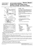
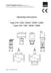
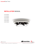
Mobile Refrigerated Cart Double Compartment Model: 1000-MR2 • Installation • Operation • Maintenance W164 N9221 Water Street • P.O. Box 450 • Menomonee Falls, Wisconsin 53052-0450 USA PHONE: 262.251.3800 • 800.558.8744 USA / CANADA FAX: 262.251.7067 • 800.329.8744 u . s . a . OnLY www.alto-shaam.com printed in u.s.a. #8411 • 08/13 ITEM NO. _______________________ 1000-MR2 mobile refrigerated cart l The Alto-Shaam Mobile refrigerated Cart is not just a refrigerator on wheels, but a well-designed and efficient system for storing and transferring refrigerated food products. Adjustable shelves allow for the storage of plated items, pans or other items. l l Full perimeter stainless steel bumper, transport handles, heavy duty casters along with the cart’s reduced height provide easy mobility. Electronic thermostat has digital display to view inside set air temperature. l l Non-magnetic stainless steel surface resists corrosion. l Environmentally safe refrigerant. l l ll mechanical equipment is easily accessible, without the use of A tools, for ease in servicing. Center mounted cooling coil balances and distributes air evenly. Condensate from the cooling coil is used to cool the compressor, therefore, it is unnecessary to have an alternate means of water disposal. l Double cavity model with 20 gauge, non-magnetic stainless steel exterior and door, fully insulated with high density foamed-in-place polyurethane. Doors include two (2) positive door latches with magnetic-mechanical closing and cylinder door lock. 22 gauge non-magnetic (non-corrosive) stainless steel interior includes four (4) removable stainless steel side racks with 50 shelf positions spaced on 1-1/4" (32mm) centers, six (6) powder coated shelves, 26-1/2" x 21-3/4" (673mm x 552mm). The mobile refrigerator is controlled by one (1) on / off switch, with a factory set temperature of 36°F (2°C). A LED display monitors the inside temperature. Unit includes one (1) transport handle on each end of the cart, and a full‑perimeter stainless steel bumper guard. Cart is furnished with removable side racks, six (6) powder coated shelves, six (6) 5” (127mm) heavy duty casters — two (2) rigid and four (4) swivel with brake and rear power cord storage during transport. One (1) 1/3 horsepower compressor system utilizes 134a refrigerant, generating 2560 BTU per hour. MODEL 1000-MR2: Double compartment Mobile Refrigerated Cart Factory installed Options l Temperature display in Fahrenheit is standard. ÂSpecify degrees Celsius on order as required. l Specify voltage requirement on order as required. Â115V Â220V W164 N9221 Water Street • P.O. Box 450 • Menomonee Falls, Wisconsin 53052-0450 • U.S.A. PHONE : 262.251.3800 800.558.8744 U . S . A ./ CANADA FAX : 262.251.7067 800.329.8744 U . S . A . ONLY www.alto-shaam.com PRINTED IN U.S.A. DUE TO ONGOING PRODUCT IMPROVEMENT, SPECIFICATIONS ARE SUBJECT TO CHANGE WITHOUT NOTICE. #411 - 08/13 1000-MR2 mobile refrigerated cart dim ens io ns : H x W x D 26-7/8" (682mm) 29-1/4" (742mm) 27" (685mm) 57-11/16" (1465mm) 27" (685mm) exterior : 68-1/2" x 67-1/2" x 29-1/4" (1740mm x 1715mm x 742mm) interior per compartment : 21-1/4" x 27-1/4" x 55-1/2" (540mm x 692mm x 1410mm) E LECTRICA L voltage phase cycle/hz 220-2401 67-1/2" (1715mm) with bumper ampskW 60 6.27 1.5 504 lb (229 kg) volume maximum : 2-1/2" (64mm) & plug TIS 166-2549 pr o duct\pa n ca pa city 64-1/2" (1638mm) 29-1/2" (749mm) 315 maximum quarts full - size pans : (399 liters ) gastronorm 1/1: Fourty-two (42) 20" x 12" x 2-1/2" (530mm x 325mm x 65mm) 55-1/2" (1410mm) 68-1/2" (1740mm) cord full - size sheet pans : Twenty-six (26)* 18" x 26" x 1" * additional on wire shelves only shelves required INSTA LL ATION RE Q UIREMENTS — C art must be installed level. — C art must not be installed in any area where it may be affected by steam, grease, dripping water, extreme temperatures, or any other severely adverse conditions. cLEARANCE RE Q UIREMENTS Full perimeter bumper accommodates all clearance requirements. 557 ± 22 lb (253 ± 10 kg) carton dimensions : ( l 31-15/16" ship : 42-3/4" x contact factory for capacity Covered “C” Carriers DC-2869 DC-23676 693 ± 22 lb Uncovered “P” Carriers DC-2868 (315 ± 10 kg) Uncovered “EP” Carriers x w x h) x Plate Carriers, Covered “EC” Carriers w eight net : OPTIONS & ACCESSORIES 70-7/8" (810mm x 1085mm x 1800mm) DC-23580 Shelves, 26-7/8" x 19-5/8" (683mm x 498mm) Powder Coated SH-35956 W164 N9221 Water Street • P.O. Box 450 • Menomonee Falls, Wisconsin 53052-0450 • U.S.A. PHONE : 262.251.3800 800.558.8744 U . S . A ./ CANADA FAX : 262.251.7067 800.329.8744 U . S . A . ONLY www.alto-shaam.com #411 - 08/13 DUE TO ONGOING PRODUCT IMPROVEMENT, SPECIFICATIONS ARE SUBJECT TO CHANGE WITHOUT NOTICE. PRINTED IN U.S.A. ALTO-SH HAAM MOBILE M E REFR RIGERA ATED C CARTS 1.0 IN NTRODUCTIO ON This tec chnical manua al provides in nformation on n the insttallation, ope eration, maintenance and d inspectio on of this unit. A com mplete parts s breakdo own is provide ed. 1.1 EQU UIPMENT DES SCRIPTION The unit consists of th he following: Storage compartment: The ins sulated food d storage compartmen nt is clear storage s area. d in this area are a the adjus stable shelves s Included and coolling coil. A to the e storage compartment is s Doors: Access through a hinged-mou unted insulate ed door. sing unit Compartment: C a Condens This area contains the conden nsing unit alo ong with the e necessary controls. c is located d Evaporator Coil: The evaporator coil in the storage compa artment and is s responsible e old air associated with the e for distributing the co refrigeration system. 1.2 EQUIP PMENT SUPPLIED The uniit is shipped d from the factory fully y assembled except the adjustable shelving thatt uire positionin ng on the sid de racks. The e will requ complete e assembly is s palletized and a crated to o reduce the t possibility y of damage e in shipping g and stora age. ADING PART TICULARS 1.3 LEA Refrigerrant: R134a Electrica al : 1000-MR R2 VAC 220-240V 60 Hz, 1 6.3 Amps 549 TIS166-25 Net 557±22 lb (253±10kg) Shipping 693±22 lb (315±10kg) ( 1000-MR2 (60HZ) OPERATION MANUAL #08/13 2.0 F FUNCTIONAL DESCRIPT TION Thi s unit is self-containe ed, automa atically ntrolled, conttinuous dutyy perishable food con sto rage system.. It is design ned with the intent d purpose off storing cold d food itemss. The and ope erating tem mperature atically is automa mo nitored by co ontrols that are e factory-set tto ma intain a prede etermined, ad dequate condition. The e unit consistss of two basicc assemblies:: a) Condensing g Unit Com mpartment which ondensing u unit, the electrical inclludes the co con ntrol panel w with power sw witch and terrminal boxx, and a heate ed condensattion evaporato or. b) S Storage Com mpartment wh hich consists of the insu ulated clear sstorage area ffor perishable e food item ms requiring a temperaturre range of 3 37° to 40°°F (3° to 4°C). The clear storage area inclludes adjusta able shelving. OPERATION 2.1 SYSTEM O The e primary fo focus for the design o of the refrrigerated cab binet is for th he safe stora age of foo d products which require refrigerration. nsiderable en ngineering atttention was p placed Con on the qualities o of function an nd serviceabillity. The e refrigeratio on system iis a closed loop sysstem. Unless the system develops a leak, add ding additiona al refrigerant iis not necessary. 3.0 START UP P PROCEDURE The e refrigeration n system is ccompletely fa actoryasssembled, prre-charged and readyy for ope eration. The ccontrol has b been set to display tem mperature in degrees Fah hrenheit or degree Cellsius as spec ified on the original order. To energize the system, it is only necessary to ate the powe er supply cord d and connecct it to loca a p proper electrrical supply source. Oncce the sup pply cord hass been conn nected to a p power sou urce, the unit can be starte ed by switchin ng the pow wer control sw witch to the "O ON" position. 3.1 SHUT-DOW WN PROCED DURE To shut-down, p place the po ower control in the FF" position a and open the e door to allo ow the "OF cab binet interior temperature e to equalize e with the room temperrature. Use e a mild dete ergent diluted d in warm wa ater to wassh the interio or and exterior surfaces o of the cab binet. 1/14 PROC CEDUR RES CONTROL L AND INDICA ATION STAR RT-UP PROCE EDURE NAME TYPE E FUNCTION Thermostat Contac ct Points Cyc cles the refrigeration system (automatic) Power Control Contac ct Points Terminates power OPER RATION RESULT TS Activa ate system by The comp pressor should electri cal service cord immediate ely come on-line into el ectrical supply and the evvaporator fan acttivate. source e Turn power switch h to the "ON" Switch(ON/O OFF) to th he unit LCD display y Indiicates continuous s With th he door closed a and The tempe erature in the sto orage cab binet temperature e the sto orage area emptty area will b begin to decrease e 3.3 EXTENDED PERIO OD OF INACT TIVITY This unit is designe ed for contin nued use att automatic cally cycled intervals. In case of an n extended shut-down n, the food storage e compartm ment must be cleaned and wiped dry to o minimize the potential of odor bu uild-up during g shutdown. positio on. of prod duct, wait for a period d of 1 hour Verify correct operatin g Cabinet w will have reached the tempe erature. Begin proper operating temperatture stockin ng the containme ent of 36°F ± 3°F(2°C ± 1°C) area w when the proper operatting temperature e has be een reached. RROR CODE ES 3.4 ER ALA ARM SIGNALS S MES SSAGE CAUSE OUTPU UTS “P1” Room m probe failure Compressor output acc. To. Par.. “Con” and “COF” “P3” Third probe failure Outputs unch hanged “P4” Outputs unch hanged “LA2”” Fourtth probe failure Maxim mum tempe erature alarm Minim mum tempe erature alarm denser high Cond tempe erature Cond denser low tempe erature “dA” Door open “EA” Exterrnal alarm Serio us external m (i1F=bAL) alarm Presssure switch alarm m (i1F=PAL) “HA” “LA” “HA2 2” “CA” “CA” Outputs unch hanged Outputs unch hanged It depends on the “Ac2”parame eter It depends on the eter “bLL” parame Compressor according to rrd Output uncha anged All outputs O OFF All outputs O OFF 1000-MR2 (60HZ) OPERATION MANUAL #08/13 2/14 OPERATIO ON / CLE EANING 4.0 OPE ERATING PRO OCEDURE The purp pose of this mobile refrig gerator is to o maintain cold food ds at prop per serving g ures. The unit should the t intended d temperatu purpose only. o a) Adjjust the po osition of the shelves s accommo odate required d storage nee eds. h the power to o the "ON" position b) Switch hill the cabine et to the full, factory f presett c) Pre-ch temperatu ure of 36°F ±3 3°F (2.C) d) Load the refrigerattor with chilled foods only. ading, use a food f thermom meter to make e Before loa certain alll products are e at a temperrature of 41°F F (5°C) max ximum or les ss. Cover foo ods to reduce e moisture build-up on the inside wall of the e T maintain th he proper refrrigerated food d cabinet. To temperatu ure, open the door only when n necessary y. The mobile e refrigerated door may be e locked if required. r 5.1 CLEANING ow appropria and local h health Follo ate state a (hyg iene) regula ations regarding all applicable quirements for food clean ning and to ssanitation req serv ice equipmen nt. LY: Wipe all sspills at once. DAIL EKLY: WEE a) Remove the wire shelves and side e rack upports. Cle ean these items shelf su separatelly using a m mild, non-abrrasive detergentt and soft clotth. b) With a mild, non-abrassive detergen nt and e the water, usse a soft ccloth to wipe interior lin ner of the storrage comparttment. Begin at the top and work down. Wipe ding the sttorage the gaskket surround compartm ment opening. c) Using a m mild detergen nt and water,, wipe the vinyl door gaskett. Make certa ain to der the gaskket to remove e any wipe und mildew orr residue. d) Wipe inte erior surfacess with a clean n cloth and sanittizing solution n for use on metal and vinyl food contacct surfaces. T This is uild-up an importtant step to ccontrol the bu of unwan nted mildew and mold o on the evaporato or coil and fan n. e) Vacuum right, left an nd back pane el grill maintain maximum air flow w. vents to m f) Wipe the e interior of th he unit with a mild e with detergentt and water. Always wipe the grain of the stainle ess steel to prrevent g the finish. scratching ANING and MAINTENANC M CE 5.0 CLEA A thorough, periodic maintenance e schedule is required to t ensure the e longest and d ouble free operation. Maintenance e most tro schedules s should be aimed at ma aximizing the e efficient use of mainten nance person nnel, reducing g down-time e, and providing the orderrly acquisition n of spare parts p support. 1000-MR2 (60HZ) OPERATION MANUAL #08/13 3/14 SCH HEDULED MAINT TENANC CE 6.0 MAIN NTENANCE 6.3 Remembe er to de-enerrgize the unit by switching g the toggle e switch locatted on the control panel to o the "OFF"" position. Dis sconnect the unit from the e power sou urce. ore making an ny adjustmentt to the therm mostat, Befo checck the door g gasket for prroper seal. P Proper adjusstment can b be tested by pulling a dolllar bill throu ugh the gassket seal and d feeling a slight resisstance. If it is determined d a proper seal is main ntained around the full perimeter o of the gaskket, a therrmostat adju ustment mayy be nece essary. NTHLY INSPE ECTION & SE ERVICE 6.1 MON CHECK THE T INLET AND A OUTLE ET ENDS OF F THE DRA AIN LINE to make certa ain there are e no obstruc ctions. If an obstruction o is found: a obstructed d Use compressed air to unblock an e in a force ed air evapo orator model. drain line Remove the t drain line at the evapo orator coil and d attach an air-line using 60 pounds s of pressure. o chemicals to clear a clo ogged drain is s The use of not recom mmended. ARLY INSPEC CTION & SER RVICE 6.2 YEA 1. INSP PECT THE DOOR GASKE ET for cracks s splits s and dryness s. 2. PECT THE MOVING M PAR RTS OF THE E INSP DOO OR LATCH as ssembly for signs s of wear. Chec ck the screw w tightness on o both latch h and strike. s 3. NGES by open ning the doorr CHECK THE HIN a to the cabinet. c With h to a 90-degree angle mum pressure e, lift up on th he outer edge e minim of the door. Replace the hinges if there is s pward movem ment of 1/2 in nch (12.7mm)) an up or mo ore. 1. 2. 3. THERMOST TAT ADJUST TMENT Access the e 'machine status' men nu by pressing and quickly relleasing the ""SET" key. The label of the "SET" folder appears. To display tthe set pointt value, presss the "SET" key ag gain. The vallue appears o on the display. he set point vvalue, use the e "UP" To change th and "DOWN" key within 15 seconds. 6.4 CONDENSE ER FAN & MOTOR RE EPLACEMENT T 1. Disconnect a all electrical p power to the u unit, 2. Remove the ventilation grrill. 3. Remove he th condensing mounting g unit base bolts and on n the slide e the refrigeration assembly out. 4. hroud from around Remove the protective sh the motor. 5. e mounting sccrews at the motor Remove the base. 6. allen wrench h, loosen the e set Using an a screw on th he blade hub b and slide blade from the sha aft. 7. Install the ne ew condense er fan by reve ersing the process. 8. otor by reverssing the proce ess. Install the mo 1000-MR2 (60HZ) OPERATION MANUAL #08/13 4/14 SCH HEDULED MAINT TENANC CE 6.6 DOOR HANDLE REPLACEME R ENT NOT TE: GE REPLACE EMENT 6.8 DOOR HING It may be necessarry to remove e y in order to o the handle assembly ough a doorr get the cabinet thro opening. NOTE: T This procedurre will require two p people. One person to ho old the d door while tthe other rem moves th he attachmen nt screws. R the th hree side mou unting screws s 1. Remove in n latch. 2. Remove R two screws in strik ke. 3. Replace R in rev verse order. 1 1. Using a screwdriver, remove the three which attach tthe butt section of screws w the hinge es to the cabin net. 2 2. With the door detache ed from the ca abinet, remove the screws which attach h the part of the hing ge to the doo or. second p 3 3. To insta all the rep placement h hinge, reverse th he process. R ENT 6.7 DOOR GASKET REPLACEME NOT TE: It is sug ggested that the door be e removed d from the cabinet and d placed fa ace down on a work table. R the fasteners and a pull old d 1. Remove ga asket from the retainer. 2. Clean C gasket retainer and immediate e arrea. 3. Start new ga asket into re etainer. Afterr asket is positioned, replace fasteners. ga E: Avoid cuttin ng the gaskett if possible. NOTE WITCH REPLA ACEMENT 6.9 POWER SW 1 1. Disconne ect the unit from the p power source. 2 2. Remove the silicone seal around the ont control leader perimeterr of the fro panel. Remove the panel by lifting straightt up. 3 3. Using a flat blade sccrewdriver re emove witch attached d. the coverr plate with sw 4 4. Remove the wires connected to o the switch. 5 5. Unscrew the lock wa asher and re emove h. the switch 6 6. Reverse the process to install the e new switch 77. Remountt the panel and resea al the silicone. 1000-MR2 (60HZ) OPERATION MANUAL #08/13 5/14 CO ORRECTIVE MAIN NTENANCE TROUBLE SH HOOTING GUIDE E SYMPTOMS S Un nit does not cool. Unitt does not ope erate. Unit runs continuo ously. POSSIBLE FAILUR RE Bad connection a at supply d. cord Ill-fittting gasket. Low refrigerant. Control failure. orrect voltage.. Inco Bad connection a at supply d. cord Faile ed compresso or. Low on Refrigera ant. Control failure. w or Resttricted air flow dirty y condenser ccoil. Bad condenser fa an or. moto Com mpressor failu re. Inefffective door sseal. Air circulation c in sstorage restrricted. Defe ective compre essor. Low refrigerant. Amb bient tempera ature too low. Bloc cked or dirty cond denser. Amb bient tempera ature too high. Systtem contains air. Refrrigerant overccharge. Mal--adjusted con ntrol. Low w head press sure. Hig gh head press sure. Short cycling g. SOL LUTION Check supply cord a at outlet. n strike on do oor Tighten latch. eaks Check system for le and reccharge. Adjust control or rep place. age. Supplyy correct volta Replacce or repair. Replacce. Leak-ccheck system and recharg ge. Adjust control or rep place. blem Rectifyy air flow prob and cle ean condense er. Check and replace iif necesssary. Replacce. Adjust door strike. nd Redistrribute food an even air flow. Replacce. Leak check system and ge. recharg Redistrribute food for even air flow. Clean a and remove a any obstrucctions. Improvve room temperrature. Evacua ate, change th he filter drryer and recha arge. Reduce e refrigerant iin the system m. Adjust control. This chart c is provided p d for the assistan nce of qu ualified ttechnicia ans only y and is not n inten nded for use by u untrained d or una authorize ed service e person nnel. 1000-MR2 (60HZ) OPERATION MANUAL #08/13 6/14 CO ORRECTIVE MAIN NTENANCE TROUBLE SH HOOTING GUIDE E 1000-MR2 (60HZ) OPERATION MANUAL #08/13 7/14 R134A 1000-MR2 (60HZ) OPERATION MANUAL #08/13 8/14 MR2-60Hz SERVICE PARTS DESCRIPTION RUBBER WHEEL 5" ROLLER BRAKE RUBBER WHEEL 5" FIX COMP.220V 60Hz COND. COIL COND.FAN MOTOR (Complete set) DRAIN HOT GAS Door Hing Door Latch Handle PVC BOX QTY PART NUMBER 3 191115 3 191154 1 1 1154459 2541011 1 I105009 1 4 2 1 048102 1811 I10835 073840 1000-MR2 (60HZ) OPERATION MANUAL #08/13 DESCRIPTION Filter Dryer Accumulator Access valve Heater Door Gasket Assy PVC.Shelf(498 x 683) Shelf Support S/S Shelf post Side Handle Evaporator coil Evaporator fan motor Power Control Switch Thermostat QTY 1 1 1 9 m. 2 8 48 12 2 1 2 1 1 PART NUMBER 13402 13510 146014 I128225 04URALTO2DB001 170149 0091041 009147 990120 26515512 I1009109 I099115 0874002CX 9/14 Parts Identification Compressor for MR2 ELECTRICAL DIAGRAM 1000-MR2 (60HZ) OPERATION MANUAL #08/13 13/14 transPortatIon DaMaGe and claIMs 1. 2. 3. 4. 5. 6. 7. 8. All Alto-Shaam equipment is sold F.O.B. shipping point, and when accepted by the carrier, such shipments become the property of the consignee. Should damage occur in shipment, it is a matter between the carrier and the consignee. In such cases, the carrier is assumed to be responsible for the safe delivery of the merchandise, unless negligence can be established on the part of the shipper. Make an immediate inspection while the equipment is still in the truck or immediately after it is moved to the receiving area. Do not wait until after the material is moved to a storage area. Do not sign a delivery receipt or a freight bill until you have made a proper count and inspection of all merchandise received. Note all damage to packages directly on the carrier’s delivery receipt. Make certain the driver signs this receipt. If he refuses to sign, make a notation of this refusal on the receipt. If the driver refuses to allow inspection, write the following on the delivery receipt: Driver refuses to allow inspection of containers for visible damage. Telephone the carrier’s office immediately upon finding damage, and request an inspection. Mail a written confirmation of the time, date, and the person called. Save any packages and packing material for further inspection by the carrier. Promptly file a written claim with the carrier and attach copies of all supporting paperwork. We will continue our policy of assisting our customers in collecting claims which have been properly filed and actively pursued. We cannot, however, file any damage claims for you, assume the responsibility of any claims, or accept deductions in payment for such claims. lIMIteD WarrantY Alto-Shaam, Inc. warrants to the original purchaser only that any original part that is found to be defective in material or workmanship will, at Alto-Shaam's option, subject to provisions hereinafter stated, be replaced with a new or rebuilt part. The original parts warranty period is as follows: For the refrigeration compressor on Alto-Shaam Quickchillers™, five (5) years from the date of installation of appliance. For the heating element on Halo Heat® cooking and holding ovens, as long as the original purchaser owns the oven. This excludes holding only equipment. For all other original parts, one (1) year from the date of installation of appliance or fifteen (15) months from the shipping date, whichever occurs first. The labor warranty period is one (1) year from the date of installation or fifteen (15) months from the shipping date, whichever occurs first. Alto-Shaam will bear normal labor charges performed during standard business hours, excluding overtime, holiday rates or any additional fees. To be valid, a warranty claim must be asserted during the applicable warranty period. This warranty is not transferable. THiS WarraNTY DOES NOT appLY TO: 1. Calibration. 2. Replacement of light bulbs, door gaskets, and/or the replacement of glass due to damage of any kind. 3. Equipment damage caused by accident, shipping, improper installation or alteration. 4. Equipment used under conditions of abuse, misuse, carelessness or abnormal conditions, including but not limited to, equipment subjected to harsh or inappropriate chemicals, including but not limited to, compounds containing chloride or quaternary salts, poor water quality, or equipment with missing or altered serial numbers. 5. Damage incurred as a direct result of poor water quality, inadequate maintenance of steam generators and/or surfaces affected by water quality. Water quality and required maintenance of steam generating equipment is the responsibility of the owner/operator. 6. Damage caused by use of any cleaning agent other than Alto-Shaam's Combitherm® Cleaner, including but not limited to damage due to chlorine or other harmful chemicals. use of alto-Shaam's Combitherm® Cleaner on Combitherm® ovens is highly recommended. 7. Any losses or damage resulting from malfunction, including loss of product, food product, revenue, or consequential or incidental damages of any kind. 8. Equipment modified in any manner from original model, substitution of parts other than factory authorized parts, removal of any parts including legs, or addition of any parts. This warranty is exclusive and is in lieu of all other warranties, express or implied, including the implied warranties of merchantability and fitness for a particular purpose. In no event shall Alto-Shaam be liable for loss of use, loss of revenue or profit, or loss of product, or for any indirect, special, incidental, or consequential damages. No person except an officer of Alto-Shaam, Inc. is authorized to modify this warranty or to incur on behalf of Alto-Shaam any other obligation or liability in connection with Alto-Shaam equipment. E ffe ct i v e N o v em ber 1, 2012 RECORD THE MODEL AND SERIAL NUMBER OF THE APPLIANCE FOR EASY REFERENCE. ALWAYS REFER TO BOTH MODEL AND SERIAL NUMBER IN ANY CONTACT WITH ALTO-SHAAM REGARDING THIS APPLIANCE. Model: ______________________________________________ Date Installed: ______________________________________________________ Voltage: ______________________________________________ Purchased From: ___________________________________________ Serial Number: _____________________________________________________________________________________________________________ W164 N9221 Water Street PHONE: ● P.O. Box 450 ● Menomonee Falls, Wisconsin 53052-0450 ● U.S.A. 262.251.3800 • 800.558-8744 USA/CANADA FAX: 262.251.7067 • 800.329.8744 U.S.A. ONLY www.alto-shaam.com PRINTED IN U.S.A.