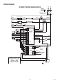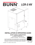
1
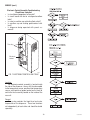
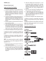
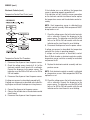
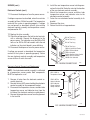
H10X
G
IN
RN ter
WA Wa e!
t ar
o
H
ry h C
Ve Wit
e
Us
!
OPERATING & SERVICE MANUAL
BUNN-O-MATIC CORPORATION
POST OFFICE BOX 3227
SPRINGFIELD, ILLINOIS 62708-3227
PHONE: (217) 529-6601 FAX: (217) 529-6644
To ensure you have the latest revision of the manual or to obtain the illustrated parts catalog, please visit the Bunn-O-Matic
website, at www.bunn.com. This is absolutely FREE, and the quickest way to obtain the latest catalog and manual updates.
Contact Bunn-O-Matic Corporation at 1-800-286-6070 to obtain a paper copy of the required Illustrated Parts Catalog mailed
via U.S. Postal Service.
10889.0000E 02/08 ©1995 Bunn-O-Matic Corporation
www.bunn.com
BUNN-O-MATIC COMMERCIAL PRODUCT WARRANTY
Bunn-O-Matic Corp. (“BUNN”) warrants equipment manufactured by it as follows:
1) All equipment other than as specified below: 2 years parts and 1 year labor.
2) Electronic circuit and/or control boards: parts and labor for 3 years.
3) Compressors on refrigeration equipment: 5 years parts and 1 year labor.
4) Grinding burrs on coffee grinding equipment to grind coffee to meet original factory screen sieve analysis:
parts and labor for 3 years or 30,000 pounds of coffee, whichever comes first.
These warranty periods run from the date of installation BUNN warrants that the equipment manufactured by
it will be commercially free of defects in material and workmanship existing at the time of manufacture and
appearing within the applicable warranty period. This warranty does not apply to any equipment, component or
part that was not manufactured by BUNN or that, in BUNN’s judgment, has been affected by misuse, neglect,
alteration, improper installation or operation, improper maintenance or repair, damage or casualty. This warranty is
conditioned on the Buyer 1) giving BUNN prompt notice of any claim to be made under this warranty by telephone
at (217) 529-6601 or by writing to Post Office Box 3227, Springfield, Illinois 62708-3227; 2) if requested by
BUNN, shipping the defective equipment prepaid to an authorized BUNN service location; and 3) receiving prior
authorization from BUNN that the defective equipment is under warranty.
THE FOREGOING WARRANTY IS EXCLUSIVE AND IS IN LIEU OF ANY OTHER WARRANTY, WRITTEN OR
ORAL, EXPRESS OR IMPLIED, INCLUDING, BUT NOT LIMITED TO, ANY IMPLIED WARRANTY OF EITHER
MERCHANTABILITY OR FITNESS FOR A PARTICULAR PURPOSE. The agents, dealers or employees of BUNN
are not authorized to make modifications to this warranty or to make additional warranties that are binding on
BUNN. Accordingly, statements by such individuals, whether oral or written, do not constitute warranties and
should not be relied upon.
If BUNN determines in its sole discretion that the equipment does not conform to the warranty, BUNN, at its
exclusive option while the equipment is under warranty, shall either 1) provide at no charge replacement parts
and/or labor (during the applicable parts and labor warranty periods specified above) to repair the defective
components, provided that this repair is done by a BUNN Authorized Service Representative; or 2) shall replace
the equipment or refund the purchase price for the equipment.
THE BUYER’S REMEDY AGAINST BUNN FOR THE BREACH OF ANY OBLIGATION ARISING OUT OF THE SALE OF
THIS EQUIPMENT, WHETHER DERIVED FROM WARRANTY OR OTHERWISE, SHALL BE LIMITED, AT BUNN’S
SOLE OPTION AS SPECIFIED HEREIN, TO REPAIR, REPLACEMENT OR REFUND.
In no event shall BUNN be liable for any other damage or loss, including, but not limited to, lost profits, lost sales,
loss of use of equipment, claims of Buyer’s customers, cost of capital, cost of down time, cost of substitute
equipment, facilities or services, or any other special, incidental or consequential damages.
BrewWISE, BUNN Gourmet Ice, BUNN Pour-O-Matic, BUNN, Bunn-OMatic, Bunn-O-Matic, BUNNlink, BUNNserve, BUNN
Espress, DBC, Dr. Brew, Dual, EasyClear, EasyGard, Easy Pour, FlavorGard, Gourmet Ice, Gourmet Juice, High Intensity,
IMIX, Infusion Series, Legendary for Quality, The Mark of Quality in Beverage Equipment Worldwide, My Café, PowerLogic, Safety-Fresh, Scale-Pro, Single, Smart Funnel, Smart Hopper, Soft Heat, SplashGard, System III, ThermoFresh,
392, AXIOM, Beverage Profit Calculator, Beverage Bar Creator, BrewLOGIC, BrewMETER, BrewWIZARD, BUNNSERVE,
BUNNsource, Coffee At Its Best, Cool Froth, Digital Brewer Control, Intellisteam, Nothing Brews Like a BUNN, Pouring
Profits, Pulse Wave, Quality Beverage Equipment Worldwide, Signature Series, Silver Series, Smart Heat, SmartWAVE,
Tea At Its Best, The Horizontal Red Line, Titan, Ultra, are either trademarks or registered trademarks of Bunn-O-Matic
Corporation.
2
10889 020608
USER NOTICES
Carefully read and follow all notices on the equipment and in this manual. They were written for your protection. All notices are to be kept in good condition. Replace any unreadable or damaged labels.
! WARNING
Fill water tank before turning - on thermostat or connecting appliance
to power source.
Use only on a properly protected
circuit capable of the rated load.
Electrically ground the chassis.
Follow national/local electrical codes.
Do not use near combustibles.
FAILURE TO COMPLY RISKS EQUIPMENT
DAMAGE, FIRE, OR SHOCK HAZARD
12593.0000
This equipment must be installed to comply
with the International Plumbing Code of the
International Code Council and the Food
Code Manual of the Food and Drug Administration (FDA). For models installed outside
the U.S.A., comply with the applicable
Plumbing /Sanitation Code.
READ THE ENTIRE OPERATING MANUAL
BEFORE BUYING OR USING THIS PRODUCT
THIS APPLIANCE IS HEATED WHENEVER
CONNECTED TO A POWER SOURCE
00831.0000F 3/98 ©1998 BUNN-O-MATIC CORPORATION
00831.0000
00656.0000
37881.0000
12537.0000
3
10889 021408
ELECTRICAL REQUIREMENTS
CAUTION - The dispenser must be disconnected from the power source until specified in Initial Set-Up.
This dispenser requires 2-wire, grounded service rated 208 or 240 volts ac, 40 amp, single phase.
(Refer to the dispenser’s dataplate for exact voltage requirement.)
Electrical Hook-Up
CAUTION – Improper electrical installation will damage electronic components.
1. An electrician must provide electrical service as specified.
2. Using a voltmeter, check the voltage and color coding of each conductor at
the electrical source.
3. Remove the side panel.
4. Install the proper electrical wiring to the terminal block.
5. Connect the dispenser to the power source and verify the voltage at the terminal
block before proceeding. Reinstall the side panel.
6. If plumbing is to be hooked-up later be sure the dispenser is disconnected
from the power source. If Plumbing has been hooked-up, the dispenser is
ready for Initial Set-Up.
PLUMBING REQUIREMENTS
This dispenser must be connected to a cold water system with operating pressure between 20 and 90
psi (138 and 620 kPa) from a 1⁄2" or larger supply line. A shut-off valve should be installed in the line before the
dispenser. Install a regulator in the line when pressure is greater than 90 psi (620 kPa) to reduce it to 50 psi
(345 kPa). The water inlet fitting is 1⁄4" flare.
NOTE - Bunn-O-Matic recommends 1⁄4" tubing for installations of less than 25 feet and 3/8" for more than 25
feet from the 1⁄2" water supply line. At least 18 inches of an FDA approved flexible beverage tubing, such as reinforced braided polyethylene or silicone, before the dispenser will facilitate movement to clean the countertop.
Bunn-O-Matic does not recommend the use of a saddle valve to install the dispenser. The size and shape of the
hole made in the supply line by this type of device may restrict water flow.
This equipment must be installed to comply with the International Plumbing Code of the
International Code Council and the Food Code Manual of the Food and Drug Administration
(FDA). For models installed outside the U.S.A., you must comply with the applicable
Plumbing/Sanitation Code for your area.
Plumbing Hook-Up
1. Flush the water line and securely attach it to the flare fitting at the rear of the dispenser.
2. Turn on the water supply.
4
10889 021408
CE REQUIREMENTS
• This appliance must be installed in locations where it can be overseen by trained personnel.
• For proper operation, this appliance must be installed where the temperature is between 0°C to 35°C.
• Appliance shall not be tilted more than 10° for safe operation.
• An electrician must provide electrical service as specified in conformance with all local and national codes
• This appliance must not be cleaned by water jet.
• This appliance is not intended for use by persons (including children) with reduced physical, sensory or
mental capabilities, or lack of experience and knowledge, unless they have been given instructions concerning use of this appliance by a person responsible for its safety.
• If the power cord is ever damaged, it must be replaced by the manufacturer or authorized service personel with
a special cord available from the manufacturer or its authorized service personel in order to avoid a hazard.
INITIAL SET-UP
CAUTION - The dispenser must be disconnected from the power source throughout the initial set-up, except
when specified in the instructions.
1. Connect the dispenser to the power source and turn on the water supply.
2. The “HEATER” LED will glow for approximately five seconds. During this time, the electronic circuitry will
check for a full tank of water.
3. If the tank is not full of water, the refill circuit will energize, indicated by the “REFILL” LED glowing. Water
will automatically flow into the tank to the proper level and then shut off.
4. When the tank is full of water, the heater circuit will energize, indicated by the “HEATER” LED glowing intermittently until the proper temperature is achieved. A completely cold tank will take approximately twenty
minutes for the water to heat.
5. The “READY” LED will glow when the proper water temperature is achieved.
NOTE - Stop dispensing if the “READY” LED is off. Dispense only when the ”READY” LED glows.
DRAINING THE DISPENSER
CAUTION - The dispenser must be disconnected from the power source throughout these steps.
1. Disconnect the dispenser from the power source.
2. Shut-off and disconnect the incoming water supply
3. Remove the small screws from the sides and front of the top panel.
4. Gently remove one of the grommets from the tank lid.
5. Insert a tube to the bottom of the tank and syphon ALL of the water out.
NOTE - The dispenser must be refilled using the INITIAL SET-UP steps before reconnecting to the power
source.
CLEANING
The use of a damp cloth rinsed in any mild, non-abrasive, liquid detergent is recommended for cleaning all
surfaces on Bunn-O-Matic equipment.
5
10889 021408
TROUBLESHOOTING
A troubleshooting guide is provided to suggest probable causes and remedies for the most likely problems
encountered. If the problem remains after exhausting the troubleshooting steps, contact the Bunn-O-Matic
Technical Service Department.
• Inspection, testing, and repair of electrical equipment should be performed only by qualified service personnel.
• All electronic components have 200-240 volt ac and low voltage dc potential on their terminals. Shorting of
terminals or the application of external voltages may result in board failure.
• Intermittent operation of electronic circuit boards is unlikely. Board failure will normally be permanent. If
an intermittent condition is encountered, the cause will likely be a switch contact or a loose connection at a
terminal or crimp.
• Solenoid removal requires interrupting the water supply to the valve. Damage may result if solenoids are
energized for more than ten minutes without a supply of water.
• The use of two wrenches is recommended whenever plumbing fittings are tightened or loosened. This will
help to avoid twists and kinks in the tubing.
• Make certain that all plumbing connections are sealed and electrical connections tight and isolated.
• This dispenser is heated at all times. Keep away from combustibles.
WARNING
• Exercise extreme caution when servicing electrical equipment.
• Disconnect the dispenser from the power source when servicing, except when electrical tests are specified.
• Follow recommended service procedures.
• Replace all protective shields or safety notices.
PROBLEM
PROBABLE CAUSE
REMEDY
Equipment will not operate.
1. No power or incorrect voltage
(A) Check the terminal block for the
correct voltage. It should be 200
to 240 volts ac across the red and
black terminals for 200 to 240 volt
models.
(B) Check circuit breakers or fuses.
2. Overflow protection switch
6
Refer to Service - Overflow protection switch for testing procedures.
See page 16.
10889 091599
TROUBLESHOOTING (cont.)
PROBLEM
PROBABLE CAUSE
Automatic refill will not operate after 1. No water
drawing hot water.
REMEDY
Check plumbing and shut-off
valves.
2. Water strainer/flow control
(A) Direction of flow arrow must be
pointing towards dispenser.
(B) Remove the strainer/flow control
and check for obstructions. Clear or
replace.
3. Overflow protection switch
Refer to Service - Overflow protection switch for testing procedures.
See page 16.
4. Liquid level system
Refer to Service - Electronic controls for testing procedures. See
page 11.
5. Solenoid valve
Refer to Service - Solenoid valve for
testing procedures. See page 17.
1. Solenoid valve
Refer to Service - Solenoid valve for
testing procedures. See page 17.
Water flows into the tank continu- 1. Liquid level system
ously. (Dispenser disconnected from
power source).
Refer to Service - Electronic controls for testing procedures. See
page 11.
Water flows into the tank con- 1. Overflow protection switch
tinuously (Dispenser connected to
power source).
Refer to Service - Overflow protection switch for testing procedures.
See page 16.
Water is cold.
Refer to Service - Limit thermostat
for testing procedures. See page
15.
2. Limit thermostat
CAUTION - Do not eliminate or bypass limit thermostat. Use only B.O.M. replacement part #23717.0003.
7
10889 101807
TROUBLESHOOTING (cont.)
PROBLEM
PROBABLE CAUSE
REMEDY
Water is cold (cont.)
3. Tank heater
Refer to Service - Tank heater for
testing procedures. See page 19.
4. Temperature control
Refer to Service - Electronic controls for testing procedures. See
page 12.
5. Dry plug protection
Check connections to Interlock
board and sheath of tank temperature probe.
1. Temperature control
Refer to Service - Electronic controls for testing procedures. See
page 12.
2. Lime build-up
Inspect the tank assembly for excess
lime deposits. Delime as required.
Water boils continuously.
CAUTION - Tanks and tank components should be delimed regularly depending on local water conditions. Excessive mineral build-up on stainless steel surfaces can initiate corrosive reactions resulting in serious leaks.
Dispenser is making unusual nois- 1. Solenoid valve
es.
The nut on top of the solenoid valve
must be tight or it will vibrate during
operation.
2. Plumbing lines
Plumbing lines should not be resting
on the counter top.
3. Water supply
(A) the dispenser must be connected
to a cold water line.
(B) Water pressure to the dispenser
must not be higher than 90 psi.
Install a regulator if necessary to
lower the working pressure to approximately 50 psi.
Ready indicator will not light. (when 1. Temperature control
temperature is within 4˚ of its selected setting.)
2. Ready Indicator LED
8
Refer to Service - Electronic controls for testing procedures. See
page 12.
Replace the indicator LED.
10889 072700
SERVICE
This section provides procedures for testing and
replacing various major components used in this
dispenser should service become necessary. Refer
to Troubleshooting for assistance in determining the
cause of any problem.
Component Access
WARNING - Disconnect the dispenser from the power
source before the removal of any panel or the replacement of any component.
P878
The limit thermostat, liquid level probe, tank heater,
and temperature sensor are located at the top of the
dispenser. Access is gained by removing the top lid,
attached with four 4-40 slotted-head screws.
WARNING - Inspection, testing, and repair of electrical equipment should be performed only by qualified
service personnel. Disconnect the dispenser fromthe
power source when servicing, except when electrical
tests are required and the test procedure specifically
states to connect the dispenser to the power source.
P878
Electronic Controls....................................... 10-14
Limit Thermostat................................................15
Safety Overflow Switch......................................16
Solenoid Valve...................................................17
Tank Heater........................................................19
Electrical Schematic...........................................20
@ The check valve, electronic control assembly,
overflow protection switch, solenoid valve, overflow
tube temperature sensor, triac assembly and terminal
block are located on the side of the dispenser. Access
is gained by removing the side panel. The panel is attached with eight 8-32 slotted-head screws.
9
10889 091599
SERVICE (cont.)
•
•
•
•
•
Electronic Control Assembly Troubleshooting:
Check these items first
Is circuit board popped out of bracket?
Is circuit board wet due to misaligned overflow
tube?
Is water in overflow cup activating float switch?
Is overflow cup not making good contact with
tank?
Is dispenser being operated with panels removed?
Triac Assy
Electronic
Control
P1991
FIG. 1 ELECTRONIC CONTROL AND TRIAC
Location:
The electronic control assembly is located inside
the side of the dispenser. Access will also be needed
to the temperature sensor, overflow tube temperature
sensor, and liquid level probe located on the tank lid
and to the triac assembly located on the inside of the
rear wall.
General:
This system controls the liquid level and water
temperature of the dispenser. These two functions
act independently of each other and should be tested
separately.
10
10889 101807
SERVICE (cont.)
9. Check the voltage across the terminals 1 & 4 of
the electronic control assembly with a voltmeter.
Connect the dispenser to the power source. The
indication must be 200 to 240 volts ac for 200 to
240 volt models after a delay of approximately 5
seconds.
10.Touch the screw head end of the probe to the dispenser housing. The indication must be 0.
11. Move the probe away from the dispenser
housing. The indication must again be 200 to 240
volts ac for 200 to 240 volt models after a delay of
approximately 5 seconds.
12.Disconnect the dispenser from the power source.
Electronic Controls (cont.)
Liquid Level Control Test Procedure
1. Disconnect the dispenser from the power source.
2. Check the voltage across terminals 3 & 4 of the
electronic control assembly with a voltmeter.
Connect the dispenser to the power source. The
indication must be 200 to 240 volts ac for 200 to
240 volt models.
3. Disconnect the dispenser from the power source. If
voltage was present as described, proceed to #4. If
voltage was not present as described, refer to the
Wiring Diagrams and check the dispenser wiring
harness.
4. Remove the pink wire from terminal 5 of the electronic control assembly.
5. Check the voltage across terminals 1 & 4 of the electronic control assembly with a voltmeter. Connect
the dispenser to the power source. The indication
must be 200 to 240 volts ac for 200 to 240 volt
models after a delay of approximately 5 seconds.
6. Disconnect the dispenser from the power source.
If voltage was present as described, reinstall the
probe, the sensing function of the system is operating
properly.
If voltage was not present as described, check the pink
probe wire and the green ground wire for continuity
and/or replace the probe.
Temperature control Flow Charts
If voltage was present as described, the liquid level
control of the system is operating properly, proceed
to #7.
If voltage was not present as described, replace the
electronic control assembly and the temperature sensor in the tank lid.
NOTE - Each electronic control assembly is calibrated
to a temperature sensor. Both components MUST be
replaced as a set.
7. Reconnect the pink wire to terminal 5 of the electronic control assembly.
8. Loosen the compression fitting, remove the probe
from the tank lid, and inspect it for mineral deposits. Replace it if necessary. Keep the exposed ends
of the probe away from any metal surface of the
dispenser.
11
10889 091599
SERVICE (cont.)
Electronic Controls (cont.)
If the indicator was on or blinking, the temperature
sensor is operating properly, proceed to #7.
If the indicator was off, check the sensor connection
on the electronic control circuit board and/or replace
the temperature sensor and the electronic control assembly.
Temperature Control Flow Charts (cont.)
NOTE - Each temperature sensor is calibrated to an
electronic control assembly. Both components MUST
be replaced as a set.
7. Check the voltage across the tank heater terminals
with a voltmeter. Connect the dispenser to the
power source. The indication must be 200 to 240
volts ac for 200 to 240 volt models while the red
indicator on the circuit board is on or blinking.
8. Disconnect the dispenser from the power source.
If voltage was present as described, the temperature
control of the system is operating properly.
If voltage was not present as described, contact
Bunn-O-Matic to order an electronic control assembly
temperature sensor, and triac assembly for evaluation
and proceed to #9.
Temperature Control Test Procedure
1. Disconnect the dispenser from the power source.
2. Check the voltage across terminals 3 & 4 of the
electronic control circuit board with a voltmeter.
Connect the dispenser to the power source. The
indication must be 200 to 240 volts ac for 200 to
240 volt models.
3. Disconnect the dispenser from the power source.
9. Replace the electronic control assembly and temperature sensor.
NOTE - Each electronic control assembly is calibrated
to a temperature sensor. Both components MUST be
replaced as a set.
10.Check the voltage across the tank heater terminals
with a voltmeter. Connect the dispenser to the
power source. The indication must be 200 to 240
volts ac for 200 to 240 volt models while the red
indicator on the circuit board is on or blinking.
If voltage was present as described, proceed to #4.
If voltage was not present as described, refer to the Wiring Diagram and check the dispenser wiring harness.
4. Connect the dispenser to the power source .
5. Observe the red indicator on the electronic control
circuit board.
6. Disconnect the dispenser from the power source.
12
10889 091599
SERVICE (cont.)
5. Install the new temperature sensor into the grommet on the tank lid. Route the wires to the location
of the new electronic control assembly.
6. Attach the temperature sensor, overflow tube
temperature sensor, and indicator wires to the
electronic control assembly.
7. Fasten the new electronic control assembly to its
bracket.
8. Reconnect the wires.
9. Review the initial set-up procedures.
Electronic Controls (cont.)
11.Disconnect the dispenser from the power source.
If voltage was present as described, return the new triac
assembly to Bunn-O-Matic for credit. The temperature
control of the system is operating properly. If voltage
was not present as described, reinstall your existing
electronic control assembly and temperature sensor,
and proceed to #12
12.Replace the triac assembly.
13.Check the voltage across the tank heater terminals
with a voltmeter. Connect the dispenser to the
power source. The indication must be 200 to 240
volts ac for 200 to 240 volt models while the red
indicator on the circuit board is on or blinking.
14.Disconnect the dispenser from the power source.
BLU to Triac Assy
TAN to Triac Assy
BLU to Triac Assy
TAN to Triac Assy
PNK to Liquid Level Probe
RED to Terminal block
RED to Solenoid
BLK to Overflow Safety Switch
GRN to Chassis Ground
WHI/BLU to Solenoid
If voltage was present as described, the temperature
control of the system is operating properly. Return
the new electronic control assembly and temperature
sensor to Bunn-O-matic for credit.
FIG. 2 WIRING CONNECTIONS
Electronic Control Removal and Replacement
NOTE - Each electronic control assembly is calibrated
to a temperature sensor probe. Both components
MUST be replaced as a set.
P1992
WHI & WHI to
Temperature Sensor
1. Remove all wires from the electronic control assembly terminals.
2. Remove the two 8-32 screws holding the electronic
control assembly to the component bracket.
3. Disconnect the temperature sensor, overflow tube
temperature sensor, and indicator wires from the
left side of the electronic control assembly board.
4. Remove the temperature sensor from the grommet
in the tank lid.
PNK & GRY to
Heater Indicator
Refill Indicator
Power Indicator
Ready Indicator
GRY & GRY
to Thermistor
P1
P2
P101
P1992
FIG. 3 WIRING CONNECTIONS
13
10889 091599
SERVICE (cont.)
3. Securely fasten the new triac assembly to the
rear panel in the same relative position as the one
removed. Bunn-O-matic recommends tightening
the nut to a torque setting of approximately 18
inch-pounds.
4. Disconnect the other ends of the old triac assembly
wires.
5. Connect the TAN and BLU wires with spade terminals of the new assembly to the electronic control
assembly, FIG. 2.
6. Connect the BLU wire with the ring terminal to the
tank heater, FIG. 12.
7. Connect the WHI/VIO wire of the new assembly to
the RED terminal at the terminal block.
Electronic Controls (cont.)
Triac Assembly Removal and Replacement
NOTE - Each triac installation requires the use of an
approved silicone heat sink compound. Bunn-O-Matic
recommends the use of Dow Corning 340 compound
or equivalent. It can be purchased direct from BunnO-Matic (P.N. M2522.1000)
1. Remove the existing triac assembly held in place
with a 10-32 hex keps nut.
2. Apply a small amount of the silicone heat sink
compound to the copper heat sink.
14
10889 091599
SERVICE (cont.)
If voltage was present as described, reconnect the black
wire and proceed to #5.
If voltage was not present as described, refer to the
Wiring Diagrams and check the dispenser wiring harness.
Limit Thermostat
Limit Thermostat
Location:
The limit thermostats are located on the tank lid. To test
the limit thermostats, access will also be needed to the
terminal block located on the side of the dispenser.
5. Check for continuity across the terminals of the
limit thermostat.
If continuity is not present as described, the circuit is
broken. Press the reset button of the limit thermostat
and recheck for continuity.
If continuity is not present as described, replace the
limit thermostat.
FIG. 5 LIMIT THERMOSTAT
Removal and Replacement:
1. Remove both wires from the limit thermostat terminals.
2. Remove the two #10-32 nuts attaching the limit
thermostat to the top of the tank.
3. Install the new limit thermostat and secure into
place with two #10-32 nuts.
4. Refer to FIG. 6 when reconnecting the wires.
P1993
Test Procedure:
1. Disconnect the dispenser from the power source.
2. There are two black wires on the limit thermostat
terminals. One comes from the terminal block. The
other goes directly to the tank heater terminal. Remove the black wire at the limit thermostat coming
from the terminal block.
3. Check the voltage across the black wire removed
from the limit thermostat and the red wire of the
terminal block with a voltmeter. Connect the dispenser to the power source. The indication must be
200 to 240 volts ac for 200 to 240 volt models.
4. Disconnect the dispenser from the power source.
BLK to Terminal Block
Reset
BLK to Tank Heater
P1776
FIG. 6 LIMIT THERMOSTAT WIRING
15
10889 091599
SERVICE (cont.)
Removal and Replacement:
1. Disconnect the black wires from the overflow protection switch.
2. Remove the nut beneath the copper overflow
cup.
3. Remove the entire switch assembly from the cup.
4. Place the new switch assembly into the cup, wires
first. Make sure that a gasket is in place around the
threaded switch stem.
Overflow Protection Switch
NOTE - The magnets must be at the top of the float and
there must be NO stainless steel washers installed for
the overflow protection switch to operate properly.
5. Install the nut beneath the copper overflow cup. Be
sure not to overtighten.
6. Reconnect the wires, FIG. 8.
P1993
FIG. 7 OVERFLOW PROTECTION SWITCH
Location:
The overflow protection switch is located within the side
of the dispenser inside the copper overflow cup.
For testing or removal of the overflow protection
switch, access may also be needed by removing the
two screws attaching the electronic control assembly
to its mounting bracket.
RED to BLK Wire from
Terminal Block
Test Procedure:
1. Once voltage is verified at the power source, check
for continuity across the overflow protection switch
red wires only until the plastic float is raised and
check that continuity returns when the plastic float
is again lowered.
RED to BLK Wire from
Electronic Control #3
P1777
FIG. 8 OVERFLOW PROTECTION WIRING
If continuity is present as described, reconnect each of
the red wires to the black wires, the overflow protection
switch is operating properly.
If continuity is not present as described, replace the
overflow protection switch.
16
10889 091599
SERVICE (cont.)
If voltage was present as described, proceed to #5.
If voltage was not present as described, refer to the
Wiring Diagrams and check the dispenser wiring harness.
Solenoid Valve
Location:
The solenoid valve is located within the side of the
dispenser on the right side near the bottom.
To test the solenoid valve, access will also be needed
to the electronic control assembly.
5. Remove both wires from the solenoid valve coil
terminals.
6. Check for continuity across the solenoid valve coil
terminals.
If continuity is present as described, reconnect the
wires and proceed to #7.
If continuity is not present as described, replace the
solenoid valve coil.
WA
R
NIN
7. Check the solenoid valve for coil action. Connect
the dispenser to the power source. Listen carefully
in the vicinity of the solenoid valve for a “clicking”
sound after approximately 5 seconds, as the coil
magnet attracts the plunger.
8. Disconnect the dispenser from the power source.
9. Reconnect the pink wire to terminal 5 of the electronic control assembly.
G
HA
ZA
VO RDOU
LT
AG S
DISC
E
PO ONNE
BE WER CT
FO
FR
RE SOUR
OM
RE
MO CE
VING
!
If the sound was heard as described and water will
not pass through the solenoid valve, there may be a
blockage in the water line before or after the solenoid
valve or the solenoid valve may require inspection for
wear and removal of waterborne particles.
If the sound was not heard as described, replace the
solenoid valve.
P1994
FIG. 9 SOLENOID VALVE
Test Procedure:
1. Disconnect the dispenser from the power source
and turn off the water supply to the dispenser.
2. Remove the pink wire from terminal 5 of the electronic control assembly.
3. Check the voltage across the solenoid valve coil
terminals with a voltmeter. Connect the dispenser
to the power source. The indication must be 200
to 240 volts ac for 200 to 240 volt models after a
delay of approximately 5 seconds.
4. Disconnect the dispenser from the power source.
Removal and Replacement:
1. Remove all wires from the solenoid valve coil.
2. Turn off the water supply to the dispenser.
3. Disconnect the water lines to and from the solenoid
valve.
4. Remove the two 8-32 slotted-head screws holding
the solenoid valve and mounting bracket to the
component bracket.
17
10889 101807
SERVICE (cont.)
Solenoid Valve (cont.)
5. Lift out the solenoid valve.
6. Remove the two 10-32 slotted-head screws holding
the solenoid valve to its mounting bracket.
7. Securely install the new solenoid valve to its mounting bracket. The direction of flow arrow must be
pointing towards the tank lid.
8. Attach the solenoid valve and mounting bracket to
the component bracket.
9. Securely fasten the water lines to and from the
solenoid valve.
10.Reconnect the wires, FIG. 10.
WHI/BLU to Electronic
Contol #1
RED to Terminal Block
RED to Electronic Control #5
P1779
FIG. 10 SOLENOID VALVE WIRING
18
10889 091599
SERVICE (cont.)
If voltage is present as described, proceed to #4.
If voltage is not present as described, replace the tank
heater.
Tank Heater
Location:
4. Remove the tank heater from the tank lid and inspect it for cracks in the sheath.
The tank heater is located in the tank lid.
If continuity is present as described, reinstall the tank
heater. The tank heater is operating properly.
If continuity is not present as described, replace the
tank heater.
FIG. 11 TANK HEATER
Removal and Replacement:
1. Remove the wires to the tank heater.
2. Remove the 8-32 nuts from the tank heater
flange.
3. Remove the tank heater.
4. Inspect the tank heater gasket and replace if necessary.
5. Securely install the new tank heater. Be certain of
a watertight seal.
6. Reconnect the wires, FIG. 12.
P1993
Test Procedure:
1. Disconnect the dispenser from the power source.
2. Check the voltage across the terminals of the tank
heater with a voltmeter. Connect the dispenser to
the power source. The indication must be 200 to
240 volts ac for 200 to 240 volt models.
3. Disconnect the dispenser from the power source.
BLU to Triac Assy
BLK to Limit Thermostat
P1780
FIG. 12 TANK HEATER WIRING
19
10889 091599
WIRING DIAGRAM
L1
BLK
GRN/YEL
L2
RED
SCHEMATIC WIRING DIAGRAM H10XA
BLK
BLK
TRIAC
LIMIT THERMOSTAT
BLK
BLU
WHI/VIO
TANK HEATER
BLK
BLK
LIMIT THERMOSTAT
RED
RED
TRIAC
BLU
BLK
OVERFLOW PROTECTION
SWITCH
RED
MAIN ON/OFF SWITCH
(Late Models only)
WHI/VIO
TANK HEATER
BLK
BLK
HEATER
WHI
WHI
PNK
GRY
GRY
PNK
PNK
GRY
PNK
GRY
REFILL
POWER
READY
GRY
GRY
P1
9
8
ELECTRONIC 7
CONTROL
6
ASSY
P2
5
4
3
2
1
PNK- 20
RED
GRN/YEL
WHI/BLU
SOL
J1
INTERLOCK
(DRY PLUG-IN)
ASSY
J2
RED
REFILL
PROBE
P101
J3
GRN/YEL
WHI/RED
BLU
TAN
BLU
TAN
RED
WHI
WHI
TEMP.
SENSOR
GRY
GRY
t°
STEAM
SENSOR
DRY LEVEL
PROBE
200-240 VOLTS AC
2 WIRE + GND
SINGLE PHASE
10888.0000C 01/07 © 1989 BUNN-O-MATIC CORPORATION
20
10889 101807