1
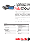
350 S. St. Charles St. Jasper, In. 47546
Ph. 812.482.2932 Fax 812.634.6632
www.ridetech.com
STR2200 62-67 Chevy II & Nova Street Challenge Package
1
SKW1016DA
Front Double adjustable Shockwaves
1
ABAR20200DA
Rear AirBar with Double adjustable 7000 series
Shockwaves
1
APOD4000LE3
5 gallon AirPod w/ LevelPro control system
1
REM8500
Two key fob remotes with antenna
1
SWA7400
Front MuscleBar sway bars with mounting kit
1
Street Challenge Shirt
350 S. St. Charles St. Jasper, In. 47546
Ph. 812.482.2932 Fax 812.634.6632
www.ridetech.com
SKW1016DA – 62-67 Chevy II & Nova Front Shockwave
Double Adjustable
2
SKW1500
255 bellows
2
SKW2602DA
2.6” smooth shock (short Double Adjustable)
2
SKW013
internal bump stop
4
SKW1701CHA
bead ring
2
SKW1751CHA
255 upper mount domed top
2
SKW1761CHA
lower mount for 255 (with set screw)
4
SKW114
small o-ring
4
SKW228
large o-ring
2
SKW022
Nova lower trunnion
4
SKW015
trunnion snap rings
4
SKW051
poly bushing halves
2
SKW010
1 ¼” stud adapter
4
SKW007
polyurethane stem bushings
2
SKW021
upper Mount Plates
2
SKW020
lower Mount Plates
2
FIT4201
1/4 x 1/4 swivel elbows
4
7/16 SAE jam nuts
upper stud
2
½” X 1 ½” Fender washer upper stud
4
3/8” x 1 ¼” USS bolts
4
3/8” USS nyloc nuts
8
3/8” SAE flat washers
8
5/16” x 1” USS bolts upper plates
8
5/16” USS Nyloc Nuts
16
5/16” SAE Flat Washers
trunnion to upper arm
Installation Instructions for SKW1016DA Front Shockwaves
1. Raise and support vehicle at a safe, comfortable working height. Let the front suspension hang
freely.
2. Remove the coil spring, shock absorber, upper shock mount, lower coil spring mount, and strut
tower reinforcement plate. Refer to a factory service manual for proper disassembly procedure.
The strut tower reinforcement plate will be reused.
1. Place the upper Shockwave plate
on top of the strut tower. Temporarily
secure the plate with two 5/16” x 1”
bolts, nyloc nuts and a flat washer on
each side.
2. With a 5/16” bit drill the two holes
closest to the engine.
3. Remove the nylocs and hold the
lower plate up to the bottom of the strut
tower and finger tighten the nylocs.
Drop the last two bolts into place then
tighten all four bolts.
4. Apply thread sealant to the air fitting
and screw it into the top of the
Shockwave.
5. Push one of the bushings down
over the stud with the step in the
bushing facing up.
6. Hold the Shockwave up to the strut
tower with the stud protruding through
the upper plate.
7. Push the other bushing down of the
stud with the step facing down. Cap it
off with a large 1/2" fender washer and
two 7/16” jam nuts.
8. Raise the upper arm up to the
Shockwave and fasten the Shockwave
trunnion to the upper arm using two
3/8” x 1 ¼” bolts, nylocs and a washer
on each side.
9. Before reinstalling the strut tower
reinforcement plate route the airline.
10. Double check air spring clearance
through full suspension travel.
11. Driving pressure should be around
85psi, but will vary to driver preference
and vehicle weight.
The care and feeding of your new ShockWaves
1. Although the ShockWave has an internal bumpstop, DO NOT DRIVE THE VEHICLE
DEFLATED RESTING ON THIS BUMPSTOP. DAMAGE WILL RESULT. The internal
bumpstop will be damaged, the shock bushings will be damaged, and the vehicle shock
mounting points may be damaged to the point of failure. This is a non warrantable situation.
2. Do not drive the vehicle overinflated or “topped out”. Over a period of time the shock valving
will be damaged, possibly to the point of failure. This is a non warrantable situation! If you
need to raise your vehicle higher that the ShockWave allows, you will need a longer unit.
3. The ShockWave is designed to give a great ride quality and to raise and lower the vehicle. IT
IS NOT MADE TO HOP OR JUMP! If you want to hop or jump, hydraulics are a better choice.
This abuse will result in bent piston rods, broken shock mounts, and destroyed bushings. This
is a non warrantable situation.
4. Do not let the ShockWave bellows rub on anything. Failure will result. This is a non
warrantable situation.
5. The ShockWave product has been field tested on numerous vehicles as well as subjected to
many different stress tests to ensure that there are no leakage or durability problems. Failures
have been nearly nonexistent unless abused as described above. If the Shockwave units are
installed properly and are not abused, they will last many, many years. ShockWave units
that are returned with broken mounts, bent piston rods, destroyed bumpstops or
bushings, or abrasions on the bellows will not be warrantied.
Adjusting shock valving
The knobs on the Shockwave will adjust the dampening characteristics of the shock absorber. One
knob is for compression and the other for rebound, they are labeled accordingly. There are 16 clicks
per knob, 1 is located fully counter clockwise and being the softest setting. We recommend 1 click
for every 10psi. This can be fine tuned to driver preference.
350 S. St. Charles St. Jasper, In. 47546
Ph. 812.482.2932 Fax 812.634.6632
www.ridetech.com
ABAR20200 Chevy II Nova Rear AirBar
SKW7000 Rear Shockwaves
2
SKW5001SA
Smooth shocks (long)
2
SKW7114
Rear bellows with ends crimped on
2
SKW013
Internal bump stop
4
SKW114
ShockWave small O ring
4
SKW227
ShockWave large O ring
2
SKW047
Upper eye mount
4
SKW057
1/2" sleeves
8
SKW048
Poly bushing halves
2
FIT4201
1/4" x 1/4" swivel 90 fitting
1
SKW100
pair of AirCan’s
AirBar Components
2
A660-1
Lower axle mounts
1
A661D-1
Lower shockwave mount
1
A661P-1
Lower shockwave mount
2
A108
Axle tabs
2
A646
Axle tabs
1
A665D-1
Upper bar mount
1
A665P-1
Upper bar mount
2
A659-1
Upper bar bolt plate
1
A662-1
Upper crossmember
2
BARTW7.375”
Upper bars (C-C length 9.50”)
2
BARWW25”
Lower bars
6
ROD302
Rubber bushings pressed into bars
4
DAYM02153
Poly bushing halves for lower bar
4
A664
Lower bar bushing sleeve
2
ROD1000
Upper bar rod end
Hardware List
6
5/8 x 2 ¾ SAE Gr.8 bolts
Bars to crossmember and brackets
6
5/8 SAE Gr.8 Nyloc Jam nuts
2
Square corner U bolts
Upper crossmember to car
12
3/8 USS nyloc nuts
Upper bar mount and crossmember
12
3/8 SAE flatwashers
4
½ x 2 ¼ Gr. 8 SAE bolts
Shockwaves to mounts
4
½ Gr.8 SAE thin nyloc nuts
4
5/8 x 1 ¼ SAE Gr8 bolts
Shockwave brackets to axle brackets
4
5/8 SAE nyloc nuts
8
7/16 SAE nyloc nuts
U-bolts
1. Raise the vehicle to a safe and comfortable working height. Use jack stands to support the vehicle
with the suspension hanging freely.
2. Support the axle and remove the leaf springs, shocks, pinion snubber, and tail pipes. Refer to the
factory service manual for proper disassemble procedures. Keep the factory upper shock bolts and
front leaf spring mounting bolts.
1. The pinion snubber mount must be
cut on the line shown in the picture. This
allows more clearance of the pinion for
maximum drop.
2. Remove the gas tank sending unit
wire from the tank and pull it into the
trunk.
3. This raised area around the gas tank
sending unit wire must be flattened to
allow the upper bar mount to sit against
the pan. The area marked in chalk can
either be pie cut, hammered flat and
welded back together or cut out
completely.
4. The upper bar mount will bolt to the
bottom of the car using the factory shock
bolts and locates off the factory shock
mount.
Note: The bar mount will point towards
the outside of the car. This is the
passenger side.
5. Using the bracket as a template drill 4
7/16” holes through the pan.
6. The upper bar bolt plate can be
dropped into place from the trunk. The
bracket will be clamped into place using
3/8” nylocs and flat washers.
7. Lower the axle enough to slide the
upper crossmember into place. The
frame is wider towards the rear of the car
as is the crossmember. Push it forward
until it is tight between the frame rails,
but make sure it is square. Drill two
holes with a 7/16” drill bit.
8. Remove the crossmember and drop
the 3/8” U-bolt through the holes.
Reinstall crossmember and tighten with
3/8” nylocs and flat washers.
Shown below:
9. Bolt the lower axle bracket to leaf
spring plate on the bottom of the axle
using the new 7/16” nylocs supplied. Do
not tighten until the lower bar is in place.
10. Install the lower arm (the longer one)
into the oem leaf spring hanger using the
factory hardware. This is a polyurethane
bushing and is lubricated at the factory
with lithium grease. Any future
lubrication can be done with any nonpetroleum based lubricant.
11. The other end of the lower bar will
attach to the axle bracket using 5/8” x 2
3/4" bolts and nylocs. This is a rubber
bushing and does not require lubrication.
Do not tighten the bar bolts yet.
12. The lower Shockwave mount is
bolted to the lower two holes of the axle
bracket with two 5/8” x 1 1/2" bolts and
nylocs The U shaped portion of the
bracket will face toward the inside of the
vehicle.
13. Bolt the axle tabs to the upper bar
as shown in the picture. Then bolt the
other end to the upper bar mount. Do
not weld the tabs yet.
14. Before welding the tabs you must
center the axle and set the pinion angle.
This must be done at ride height. Raise
the axle until the is 14 1/2" from center
eye to center eye on the Shockwave
mounts, this is ride height. One trick that
we use to maintain the settings are to
tack weld a 4” spacer between the axle
and the frame.
15. How do you set the pinion
angle? On a single-piece
shaft you want to set it up
where a line drawn through the
center of the engine crankshaft
or output shaft of the
transmission and a line drawn
through the center of the
pinion are parallel to each
other but not the same line.
A simple way to do this is to
place a digital angle finder or
dial level on the front face of
the lower engine pulley or
harmonic balancer. This will
give you a reading that is 90
degrees to the crank or output
shaft unless you have real
problems with your balancer.
At the other end, you can
place the same level or angle
finder against the front face of
the pinion yoke that is also at
90 degrees to the centerline.
If you rotate the yoke up or
down so both angles match,
you have perfect alignment.
Road testing will tell you if
you have it right. If you
accelerate and you get or
increase a vibration, then the
pinion yoke is too HIGH.
Rotate it downward in small
increments of a degree or two
until the problem goes away.
If you get or increase a
vibration when decelerating,
then the pinion yoke is too
LOW. Rotate it upward to
correct it.
16. Axle center is best determined by
dropping a plum on the outside of the
quarter panel and measuring into the
axle. This must be done with the car
level from side to side.
17. Once everything has been doublechecked you can tack weld the tabs the
axle. After removing the upper bar from
the tabs you can finish welding the tabs.
This will prevent you from frying the
bushings.
18. Reinstall the upper bar and snug all
bar bolt with the axle still at ride height.
The 4” spacer can now be removed.
19. A new 3/4" hole must be drilled for
the sending unit wire. You can reuse the
original grommet.
20. Apply thread sealant the air fitting
and screw it into the top of the
Shockwave.
21. The Shockwave will be secured into
place with 1/2" x 2 1/4" bolts and nylocs.
22. Check clearance with brake lines,
parking brake and vent tubes.
23. The exhaust can either be rerouted
under the axle or a turn down can be
installed.
24. Ride height will be around 80 psi with
about 3-4 clicks.
SKW 7000
1.750 1.375
Compressed Height
Ride Height
Extended Height
11.5”
14.5”
16.5”
Ø4.00
2.625" WITH 10.66" SHOCK
3.375" WITH 11.56" SHOCK
5.00" WITH 13.50" SHOCK
The care and feeding of your new ShockWaves
6. Although the ShockWave has an internal bumpstop, DO NOT DRIVE THE VEHICLE
DEFLATED RESTING ON THIS BUMPSTOP. DAMAGE WILL RESULT. The internal
bumpstop will be damaged, the shock bushings will be damaged, and the vehicle shock
mounting points may be damaged to the point of failure. This is a non warrantable situation.
7. Do not drive the vehicle overinflated or “topped out”. Over a period of time the shock valving
will be damaged, possibly to the point of failure. This is a non warrantable situation! If you
need to raise your vehicle higher that the ShockWave allows, you will need a longer unit.
3. The ShockWave is designed to give a great ride quality and to raise and lower the vehicle. IT
IS NOT MADE TO HOP OR JUMP! If you want to hop or jump, hydraulics are a better choice.
This abuse will result in bent piston rods, broken shock mounts, and destroyed bushings. This
is a non warrantable situation.
8. Do not let the ShockWave bellows rub on anything. Failure will result. This is a non
warrantable situation.
9. The ShockWave product has been field tested on numerous vehicles as well as subjected to
many different stress tests to ensure that there are no leakage or durability problems. Failures
have been nearly nonexistent unless abused as described above. If the Shockwave units are
installed properly and are not abused, they will last many, many years. ShockWave units
that are returned with broken mounts, bent piston rods, destroyed bumpstops or
bushings, or abrasions on the bellows will not be warrantied.
Adjusting shock valving
The knob on the bottom of the Shockwave will adjust the dampening characteristics of the shock
absorber. There are 16 clicks total, 1 is located fully counter clockwise and being the softest setting.
We recommend starting with about 3-4 clicks. This can be fine tuned to driver preference.
350 S. St. Charles St. Jasper, In. 47546
Ph. 812.482.2932 Fax 812.634.6632
www.ridetech.com
APOD4100LE3 LevelPro AirPod Compressor System
1
5 gallon AirPod
1
CON8002
2
6-32 x 3/8” Phillips pan head screw for display
1
WIR3400
Display Harness
1
WIR8360
Height sensor harness (2 short – 2 long)
4
SEN001
Height sensor
10
Heat shrink tubes
4
SEN002
1
2
2
1
1
WIR
External power harness
1
WIR5000
Fuse holder
1
WIR5040
40 amp fuse
1
#10 Yellow butt connector
1
#10 5/16” eye connector
2
ARL2000
30’ roll of ¼” airline
4
FIT4201
¼”npt x ¼”airline fitting
1
Installation Guide
RidePro E3 Display
Hardware kit for height sensor (includes the following)
Steel linkage rod
Rubber rod ends
¼” sensor bolts w/ Nyloc nuts & flat washers
Mounting tab