1
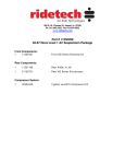
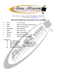
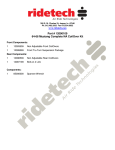
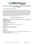
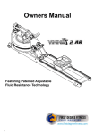
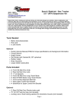
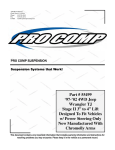
350 S. St. Charles St. Jasper, In. 47546
Ph. 812.482.2932 Fax 812.634.6632
www.ridetech.com
Part # 11060399
59-64 Impala Level 3 Complete Air Suspension System
Street Challenge Package
Front Components:
1
11053011
TQ Series Front Shockwaves
1
11052899
Front Lower StrongArms
1
11053699
Front Upper StrongArms
1
11059100
Front MuscleBar Sway Bar w/ PosiLinks
1
11059400
Billet Tie Rod Adjusters
Rear Components:
1
11054699
Rear CoolRide Kit for StrongArms
1
11050711
TQ Series Rear Shocks
1
11054499
Rear Lower StrongArms
1
11066699
Rear Upper StrongArm & Panhard Bar Kit
1
11059102
Rear MuscleBar Sway Bar
Compressor System:
1
30314100
5 gallon AirPod w/ LevelPro Control System
1
30400034
4 Pack of LevelPro Height Sensors
1
31008500
Key Fob Remote Controls
350 S. St. Charles St. Jasper, In. 47546
Ph. 812.482.2932 Fax 812.634.6632
www.ridetech.com
Part # 11053011
58-64 Impala Front TQ Series Shockwaves
For Use w/ StrongArms
ShockWave Assembly:
2
24090199
255c double convoluted bellow assembly
2
24329999
2.6” stoke TQ Series shock
2
70008913
Locking ring
2
90001994
.625” I.D. bearing
4
90001995
Bearing snap ring
2
90009989
2.75” Stud Top - Adjustable
Components:
2
90002309
2.75” Delrin stud top base
2
90001902
Aluminum cap for Delrin ball
2
90001903
Delrin ball upper half
2
90001904
Delrin ball lower half
2
31954201
¼”npt x ¼” tube swivel elbows
4
90002221
Reservoir mount
1
85000003
4mm Allen wrench
Hardware:
2
99562003
9/16” SAE Nylok jam nut
Stud top hardware
12
99050000
4mm x .5” socket head cap screw
Reservoir mounts
Installation Instructions
3. Viewed to the left is the underside of
the coil spring pocket.
4. Apply thread sealant to elbow fitting
and screw into the Shockwave.
Note: On some cars the coil spring
retainer may also need to be trimmed to
ensure that the stud top does not come
in contact with it.
5. Insert the swivel stud top through the
factory shock hole and secure with a 5/8”
Nylok nut and flat washer. The air
fitting must be towards the outside of
the car. The bellow can be rotated
separate of the shock to alter the air
fitting location.
6. Attach the Shockwave to the lower
arm using the hardware and spacers
supplied w/ the lower arm.
12. Although cutting the frame is
typically not required on this car, check
air spring clearances through full
suspension travel. Allowing the air
spring to rub will result in failure and
is not a warrantable situation.
13. The best ride quality will occur
around 50-60% suspension travel,
depending on vehicle weight this
typically occurs around 105-110 psi.
1. Stud top aluminum base
2. Delrin ball lower half
3. Delrin ball upper half
4. Aluminum cap
5. 9/16” SAE Nylok jam nut
6. Threaded stud (screwed onto shock shaft)
7. Rebound adjusting knob
8. Screw
The care and feeding of your new ShockWaves
1. Although the ShockWave has an internal bumpstop, DO NOT DRIVE THE VEHICLE DEFLATED RESTING ON
THIS BUMPSTOP. DAMAGE WILL RESULT. The internal bumpstop will be damaged, the shock bushings will
be damaged, and the vehicle shock mounting points may be damaged to the point of failure. This is a non
warrantable situation.
2. Do not drive the vehicle overinflated or “topped out”. Over a period of time the shock valving will be damaged,
possibly to the point of failure. This is a non warrantable situation! If you need to raise your vehicle higher that
the ShockWave allows, you will need a longer unit.
3. The ShockWave is designed to give a great ride quality and to raise and lower the vehicle. IT IS NOT MADE TO
HOP OR JUMP! If you want to hop or jump, hydraulics are a better choice. This abuse will result in bent piston
rods, broken shock mounts, and destroyed bushings. This is a non warrantable situation.
4. Do not let the ShockWave bellows rub on anything. Failure will result. This is a non warrantable situation.
5. The ShockWave product has been field tested on numerous vehicles as well as subjected to many different stress
tests to ensure that there are no leakage or durability problems. Failures have been nearly nonexistent unless
abused as described above. If the Shockwave units are installed properly and are not abused, they will last many,
many years. ShockWave units that are returned with broken mounts, bent piston rods, destroyed
bumpstops or bushings, or abrasions on the bellows will not be warrantied.
350 S. St. Charles St. Jasper, In. 47546
Ph. 812.482.2932 Fax 812.634.6632
www.ridetech.com
Part # 11052899
58-64 Impala Front Lower StrongArms
For Use w/ Shockwaves or CoilOvers
Components:
1
90000474
Driver side lower Arm
1
90000475
Passenger Side Arm
2
90000676
Cross shaft
2
9000677
Cross shaft clamp
4
90000906
Lower control arm bushing
1
90000476
Driver side steering stop
1
90000477
Passenger side steering stop
2
90000904
Ball joint
4
90002062
Aluminum bearing spacer
2
Grease Fittings
Hardware Kit:
2
99371011
3/8” x 6 ½” USS bolt
Sway bar end link
2
99372002
3/8” USS Nylok nut
Sway bar end link
4
99311001
5/16” X 1” USS bolts
Steering stop to lower arm
4
99313002
5/16” SAE flat washer
Steering stop to lower arm
4
99312003
5/16” Nylok Nut
Steering stop to lower arm
4
99431004
7/16” x 2” SAE Gr.8 bolt
Lower arm cross shaft clamp to frame
4
99431006
7/16” x 1 ¼” SAE Gr. bolt Lower arm cross shaft
4
99503004
½” Fender washer
Lower arm cross shaft
8
99433003
7/16” lock washer
Lower arm cross shaft & clamp
2
99501013
½” x 3 ¼” SAE Gr. 8 bolt
Shockwave to lower arm
2
99502002
½” SAE Nylok
Shockwave to lower arm
Installation Instructions
Note: These arms will not work with stock 1958 spindles.
1. Raise and support car at a safe, comfortable working height. Let the front suspension
hang freely.
2. Remove coil spring, shock absorber, and lower control arm. Refer to factory service manual for
proper disassembly procedure.
3. Bolt the lower StrongArm shaft to the
frame. 7/16” x 2” bolts, lock washers and
flat washer will be used to fasten the
aluminum clamp to the frame.
4. Slide the ball joint boot over the ball
joint stud. Slide the stud through the
spindle, secure assembly w/ new castle
nut and cotter pin supplied.
5. Attach the adjustable steering stop to
the lower arm using two 5/16” x 1” bolts.
This can be adjusted to maintain tire/shock
clearances.
6. Attach the ShockWave to the lower
StrongArm using the ½” x 3 ¼” bolts and
aluminum spacers provided.
7. The sway bar end link must be
shortened to 2” tall optimize clearance and
alignment. Use the shorter 3/8” x 6 ½” bolt
supplied. (Discard if using RideTech
MuscleBar)
8. Check all clearance with brake lines,
airlines, tie rod, sway bar, and tire through
full suspension travel and turn wheel lock
to lock.
58-64 Chevy Drivers Side Lower StrongArm
350 S. St. Charles St. Jasper, In. 47546
Ph. 812.482.2932 Fax 812.634.6632
www.ridetech.com
Part # 11053699
58-64 Impala Front Upper StrongArms
Components:
1
90000478
Passenger side Upper Arm
1
90000479
Driver side Upper Arm
2
90000905
Ball Joints
2
90000907
Cross shaft bushing
2
90000927
Upper Cross Shaft
Hardware:
4
99371014
3/8” x 1 ¼” SAE Gr. 8 bolt Upper cross shaft
4
99373001
3/8” Fender washer
Upper cross shaft
Installation Instructions
1. Drop the ball joint down through the
ball joint plate, secure w/ the hardware
supplied.
2. Fasten the upper arm to the frame
using the factory hardware. Reinstall
the current alignment shims, but
vehicle must be realigned. This arm
was designed with an extra 2 degrees
of positive caster allowing the car to be
aligned with up to 4 degrees of positive
caster. (This will vary from car to car.)
3. Insert the ball joint stud through the
spindle and install new castle nut and
cotter pin supplied.
58-64 Impala Driver Side Upper StrongArm
350 S. St. Charles St. Jasper, In. 47546
Ph. 812.482.2932 Fax 812.634.6632
www.ridetech.com
Part # 11059100
58-64 Impala Front MuscleBar
w/ PosiLinks
Components:
1
90000127
1 ¼” Diameter sway bar
2
90000124
Sway bar arm
1
90000736
Driver side frame bracket
1
90000737
Passenger side frame bracket
2
90001098
1 ¼” I.D. Polyurethane bushing
2
90000922
12mm straight PosiLink
2
90000921
12mm 90 degree PosiLink
2
90000089
T-bushing for lower control arm
1
90001092
Tube of lithium grease
2
¼” – 28 straight grease fitting
Hardware:
2
99122002
4
99122001
2
99433002
6
99431001
6
99432001
12
99433002
4
99371003
4
99372002
8
99373003
8
99371017
8
99373005
12 x 1.75 x 45mm stud
12mm Nylok nut
7/16” SAE flat washer
7/16” x 1” USS bolt
7/16” USS Nylok nut
7/16 SAE flat washer
3/8” x 1” USS bolt
3/8” USS Nylok nut
3/8” SAE flat washer
3/8” x 1” USS button head
3/8” lock washer
PosiLink (use Loctite)
PosiLink
PosiLink to lower arm
Frame bracket to frame
Frame bracket to frame
Frame bracket to frame
Frame bracket to frame
Frame bracket to frame
Frame bracket to frame
Attaches sway bar arm to bar
Attaches sway bar arm to bar
SWA7200-P Installation Instructions
*****This sway bar is designed for use with our StrongArms******
1. Apply lithium grease to the
polyurethane bushing and slide it
over the sway bar.
Note: Do not use petroleum based
lubricants on polyurethane.
2. Place the frame bracket over the
poly bushing. Bolt the assembly to
the frame, the rear two holes in the
bracket will align with the factory
sway bar mounting holes.
3. Two of the three holes on the
front of the bracket will align with
existing holes. The outer hole must
be drilled to 7/16”.
4. Bolt the sway bar arm to the bar
using four 3/8” x 1” button head bolts
and lock washers. The holes in the
frame may need to be drilled out
slightly.
5. Attach the 90 degree end of the
PosiLink to the arm using a 12mm
Nylok nut.
6. Attach the straight end to the
lower control arm. A T-bushing is
required between the PosiLink and
the lower control arm. A 12mm
Nylok nut and flat washer will secure
the PosiLink to the lower arm.
Check clearance though full suspension travel and turn the wheel lock to lock. Ensure that
the PosiLinks to not bind. Check PosiLink clearance with tie rods.
350 S. St. Charles St. Jasper, In. 47546
Ph. 812.482.2932 Fax 812.634.6632
www.ridetech.com
Part #11059400
58-64 Impala Billet Tie Rod Adjuster
2
90000091
5/8” x 8” Billet tie rod adjuster
2
99800002
5/8” SAE Right hand thread jam nut
2
99800003
5/8” SAE Left hand thread jam nut
350 S. St. Charles St. Jasper, In. 47546
Ph. 812.482.2932 Fax 812.634.6632
www.ridetech.com
Part # 11054699
58-64 Impala Rear CoolRide Kit
For Use w/ Lower StrongArms
Components:
2
90006873
Rear air spring
1
90000463
Driver side upper air spring bracket
1
90000464
Passenger side upper air spring bracket
2
31954201
¼”npt x ¼” tube swivel elbows
2
90000472
1.5” O.D x 1.5” long aluminum bump stop spacer
2
90001082
Short bump stop
Hardware:
2
99435001
7/16” x 6” stud
Upper air spring bracket to frame
2
99433002
7/16” SAE flat washer
Upper air spring bracket to frame
2
99432001
7/16” USS Nylok nut
Upper air spring bracket to frame
4
99372002
3/8” USS Nylok nut
Upper air spring bracket
8
99373003
3/8” flat washer
Air spring mounting / Bump stop
2
99371003
3/8” x 1” USS bolt
Bump stop
2
99371001
3/8” x 3/4” USS bolt
Air spring to lower arm
4
99373005
3/8” lock washer
Air spring to lower arm / Bump stop
Installation Instructions
1. Raise and support vehicle at a safe and comfortable working height.
2. Support axle then remove coil spring, shock, and bump stop. Refer to service manual for proper
disassembly procedure.
3. Apply thread sealant to the air
fitting and screw it into the top of
the air spring.
4. Place the upper cup bracket on top
of the air spring and secure with two
3/8” Nylok nuts and flat washers.
5. Thread the 6” stud into the nut in
the bottom of the cup.
6. Place the air spring assembly into
the coil spring pocket with the tab on
the side of the cup aligning with the
factory bump stop mount.
7. The stud should poke through the
hole in the upper coil spring pocket.
Some cars may not have this hole and
it must be drilled. Fasten with a 7/16”
Nylok nut and flat washer.
8. Fasten the aluminum bump stop
spacer to the frame using a 3/8” x 1”
bolt, flat washer and lock washer.
9. Screw the bump stop into the
spacer.
10. Fasten the air spring to the lower
StrongArm using a 3/8” x 3/4" bolt, lock
washer and flat washer.
11. Make sure that the air spring
cannot rub on anything at anytime.
This will result in air spring failure and
is a not a warrantable situation.
12. Ride height on this air spring is
approximately 5” tall, but may vary to
driver preference.
350 S. St. Charles St. Jasper, In. 47546
Ph. 812.482.2932 Fax 812.634.6632
www.ridetech.com
Part # 11050711
58-64 Chevy Impala Rear TQ Series Shock Kit
Shock Assembly:
2
24379999
7” TQ Series shock
2
90002024
1.7” eyelet - rebound adjustable
4
90001994
.625” bearing
8
90001995
Bearing snap ring
2
90002060
Extended T-bar (installed in shock body)
2
90001980
Snap ring for T-bar
Components:
4
90002067
Aluminum spacer for .625” bearing
2
90002221
Reservoir mount
1
85000003
4mm Allen wrench
Hardware:
4
99371004
3/8” x 1 ¼” USS bolt
Shock to frame
4
99372002
3/8” USS Nylok nut
Shock to frame
8
99373003
3/8” SAE flat washer
Shock to frame
2
99502002
½” SAE Nylok Nut
Shock to lower stud
2
99503001
½” SAE flat washer
Shock to lower stud
12
99050000
4mm x .5” allen screw
Reservoir mount
350 S. St. Charles St. Jasper, In. 47546
Ph. 812.482.2932 Fax 812.634.6632
www.ridetech.com
1. Attach shock T-Bar to frame using
3/8” x 1 ¼” bolts, Nylok nuts and flat
washers.
2. Attach the bottom of the shock to
factory shock stud using the ½”
Nylok nut & flat washer supplied.
Install one aluminum spacer on each
side of the bearing.
350 S. St. Charles St. Jasper, In. 47546
Ph. 812.482.2932 Fax 812.634.6632
www.ridetech.com
Part # 11054499
58-64 Impala Rear Lower StrongArms
For Use with CoolRide
Components:
2
90000466
Lower control arm w/ air spring mount
4
90001085
Poly bushing half – 1.5” O.D x 1.5” long
4
90001086
Poly bushing half – 1.5” O.D. x 1” long
4
90000467
Bushing sleeve – 2.5” long
Hardware:
4
99621005
5/8” x 3 ½” SAE Gr.8 bolt Lower arm
4
99622006
5/8” SAE Nylok jam nut
Lower arm
Installation Instruction
1. Raise and support vehicle at a safe and comfortable working height.
2. Fasten the lower StrongArms to the frame
and axle using the 5/8” x 3 ½” bolt and Nylok
nuts supplied.
3. Thread the 3/8” x 3/4” bolt with washer and
lock washer about half way into the air spring.
Slide bolt into slot on lower arm and tighten.
Note: Do one side at a time to keep axle from
rotating.
350 S. St. Charles St. Jasper, In. 47546
Ph. 812.482.2932 Fax 812.634.6632
www.ridetech.com
Part # 11066699
59-64 Chevy Impala Rear Upper Strong Arm & Panhard Bar Kit
Components:
1
90001119
Upper control arm – (set at 13.75”)
1
90001589
Kevlar lined Heim end – 5/8” I.D.
1
90001085
Poly bushing half – 1.5” O.D. x 1.5” long
1
90001086
Poly bushing half – 1.5” O.D. x 1” long
1
90000467
Bushing sleeve – 2.5” long
2
90002066
Aluminum bearing spacer
1
90000993
Panhard bar
1
90001942
Rubber bushing – pressed into panhard bar
1
90001946
Panhard Kevlar lined Heim end – 3/4" I.D.
2
90000460
Aluminum T bushing – for heim end
1
90000461
Panhard bar stud
Hardware:
2
99603003
5/8” USS flat washer
Panhard bar stud
1
99563001
9/16” USS flat washer
Panhard bar stud
1
99561001
9/16” x 2 ½” SAE Gr.8 bolt
Panhard bar to frame
2
99562001
9/16” SAE Nylok nut
Panhard bar
2
99752004
3/4"-16 Jam nut
Heim ends
2
99621005
5/8” x 3 ½” SAE Gr.8 bolt
Upper arm
3
99622006
5/8” SAE Nylok jam nut
Upper arm / Pan hard bar stud
Installation Instructions
1. Bolt the upper StrongArm to the
frame using the 5/8” x 3 ½” bolts and
Nylok nuts supplied. An aluminum
washer must installed on each side of
the spherical bearing.
2. Using a 5/8” x 3 ½” bolt fasten the
poly bushing end of the upper bar to
the axle bracket.
Note: Some vehicles have two factory
upper arms and need a second tubular
arm.
3. Install the ¾” jam nut onto the end of
the Heim end, then screw Heim end
into the end of the panhard bar.
4. Press the aluminum T-bushings into
the Heim end. Fasten the Heim end to
the frame bracket using the 9/16” x 2
½” bolt and Nylok nut supplied.
5. Bolt the new panhard bar stud onto
the axle in factory stud location using
the 9/16” Nylok nut and flat washer
supplied.
6. Slide the rubber end of the panhard
bar onto the stud and secure with 5/8”
thin Nylok nut and flat washer.
350 S. St. Charles St. Jasper, In. 47546
Ph. 812.482.2932 Fax 812.634.6632
www.ridetech.com
Part # 11059102
58-64 Impala Rear MuscleBar
Components:
1
90001778
Rear sway bar
2
99800004
1” Sway bar bushing & clamp kit
2
90001999
Frame bracket
2
90000740
Axle bracket
2
90000088
3” U-bolts
2
90001998
End link
4
90001583
Inner sleeve for end link
8
90001596
Poly bushing half for end link
2
90001997
Welded bolt plate
2
90001092
Tube of lithium grease
Hardware:
2
99501010
½” x 2 ¼” SAE Gr. 8 bolt
2
99501011
½” x 2 ½” SAE Gr. 8 bolt
4
99502002
½” SAE Nylok jam nut
8
99432001
7/16” USS Nylok nut
8
99433002
7/16” SAE flat washer
Before you proceed, please see the Special Notice on page 5 regarding frame type.
1)
Securely block the front wheels of the vehicle and jack up the rear end. Support the rear end on jack
stands and place the jack under the rear end for later use. You will have to have the rear axle at
approximate normal ride height to install the rear sway bar in a later step.
2)
Begin by placing the u-bolts from hardware kit #T1722 over the rear axle. Place them roughly the same
distance from the center of the axle, with the ends of the u-bolts pointed straight down. See the picture
below for approximate spacing of the u-bolts when installed.
3) Use the grease pack provided to apply a heavy coat of grease to the inside of the sway bar bushings.
Place the bushings over the bar. Push the brackets onto the sway bar bushings.
4)
Use the grease provided to apply a heavy coat of grease to the sides of the bushings on the “dog bone”
end links. Attach the mounting brackets to the end links using the shorter bolt from hardware kit #T1712.
Attach the other end of the links to the sway bar using the longer bolt. Leave the attaching hardware loose.
When attaching the hardware, the large washer should be used to contact bushing surfaces and the
small washer should be used to contact metal sway bar surface. This prevents the bolt from pulling
through the bushing.
5)
Hang the sway bar from the u-bolts on the axle. Slide the axle mount bracket over the ends of the u-bolts.
Hold the sway bar up into place with the bushing retainer brackets mounted to the axle bracket.
Install with the nuts loosely started onto the u-bolts so that the sway bar hangs freely from the axle. Use the
anti-seize provided with the u-bolts to lubricate the threads. Failure to lubricate the threads can destroy
the nylock nuts and possibly break the u-bolt or seize the nut in place when tightened.
With the bar hanging freely you can slide the u-bolts along the axle until the bar is centered with the vehicle.
Tighten down the nuts on the u-bolts to secure the position of the u-bolts and brackets.
6)
Loosely tighten the hardware connecting the end links and brackets to the bar. Leave just enough “slop” in the
connections to allow the bar to rotate easily but still be fairly tight.
7)
With the hardware loosely tightened you can now rotate the bar up, so that the brackets are resting against
the frame. Once the brackets are in place use a scribe or similar tool to mark each hole for drilling. Drill out
the holes for the brackets to 7/16” diameter. To accurately determine the location of the holes the end links
must not be loose enough to move left or right. Make certain the axle is at its normal driving height for
an accurate fit.
8)
Once the holes are drilled, use a coat hanger to loop around one stud on the retainer bracket. Slide the
bracket in through the rear end of the frame until the studs fall through the holes. Hold one stud and push
the other stud back through the hole to slide the coat hanger loop off the stud.
9)
Rotate the sway bar so that you can bolt the brackets up to the stud plate in the frame using the 7/16”
hardware from kit #T1719. You will only be using four of the nuts and the four smaller washers on the
studs. The four additional nuts and washers are extra hardware not used on this kit and may be discarded.
Tighten the nuts on the brackets and the end link hardware. Torque the end link hardware to 30ft/lbs.
You can also adjust the stiffness of the bar by changing the hole the end link mounts to. The hole nearest to
the end of the bar softens the bar stiffness by lengthening the bar. The hole furthest from the end of the bar
stiffens the bar by shortening the length of the bar.
10)
Check that all hardware is tight. Cover the grease fittings with the zerk caps provided. Remove the jack and
jack stands and you’re finished installing the sway bar set!
IMPORTANT NOTICE!!!
For some models, the vehicle may have a different rear section of the chassis frame. This alternate
type of frame ends it’s fully boxed tubing and transitions to a C-channel type.
(See below) ↓
IF your vehicle has this type of frame, you must use hardware kit # 1750 and proceed to the
following special instructions.
Since the intersection between the box tubing and C-channel prevents you from using the retainer
bracket, an alternative method will be used to mount the end link clevis brackets to the frame. We will
use 2 bolts & washers to replace the retainer bracket.
Securely block the front wheels of the vehicle and jack up the rear end. Support the rear end on jack
stands and place the jack under the rear end for later use. You will have to have the rear axle at
approximate normal ride height to install the rear sway bar in a later step.
Begin by placing the u-bolts from hardware kit #T1722 over the rear axle. Place them roughly the
same distance from the center of the axle, with the ends of the u-bolts pointed straight down. See the
picture below for approximate spacing of the u-bolts when installed.
»
Use the grease pack provided to apply a heavy coat of grease to the inside of the sway bar bushings.
the bushings over the bar. Push the brackets onto the sway bar bushings.
»
Hang the sway bar from the u-bolts on the axle. Slide the axle mount bracket over the ends of
the u-bolts. Hold the sway bar up into place with the bushing retainer brackets mounted to the axle
bracket.
Install with the nuts loosely started onto the u-bolts so that the sway bar hangs freely from the axle.
Use the anti-seize provided with the u-bolts to lubricate the threads. Failure to lubricate the
threads can destroy the nylock nuts and possibly break the u-bolt or seize the nut in place when
tightened.
With the bar hanging freely you can slide the u-bolts along the axle until the bar is centered with the
vehicle. Tighten down the nuts on the u-bolts to secure the position of the u-bolts and brackets.
»
Install the ½”-20 x 4” bolt through the sway bar hole and dogbone end link as shown in the
picture. Lightly tighten hardware.
Hardware Order from Inboard to Outboard
1.
2.
3.
4.
5.
6.
7.
8.
»
Bolt (½”-20 x 4”)
Small Washer
Swaybar
3 Spacers
Large Washer
Dogbone
Large Washer
Nylock Nut
Install the Clevis Bracket onto the dogbone endlink. Lightly tighten.
»
To accurately determine the location of the holes, the end links must NOT be loose enough to move left or right. Make certain the axle is at its normal
driving height for an accurate fit. With the hardware lightly tightened, you can now rotate the bar up, so that the brackets are resting against the frame. Make sure
both clevis brackets lay in the center of the frame. Position the clevis bracket onto the frame so that it will be possible to use either hole on the sway bar end.
»
With a marker or scribe, mark the frame for the mounting holes. Drill out the holes to accept a 7/16” bolt. Do this for both sides.
»
Once the holes are drilled, grab a 7/16” x 1.25” bolt (longer) and a 7/16” washer. Using a telescoping magnet wand, fish the bolt and washer through the
box tubing and set the bolt into it’s drilled out hole.
»
Uninstall the clevis bracket & dogbone from the sway bar for now. It will be easier to install the bracket detached from the sway bar.
»
Here’s a quick example of how the hardware should install. Fully tighten these bolts at this time. You may need to use one of the provided spacers to make
up for the uneven surface of the frame. Your kit comes with 2 thin spacers and 2 thick spacers.
»
Once the clevis brackets are installed, loosen, but do not remove, the U-bolts holding the axle
clamps. This eases swaybar centering and attaching the endlinks to the dogbones.
»
Attach the dogbones to the clevis bracket.
»
Attach the swaybar to the dogbones.
»
After all the hardware is loosely in place, fully tighten the hardware starting with the U-bolts.
Make sure the U-bolts are facing straight down. Finish off the install by tightening the dogbone
hardware. Your Done!!!
350 S. St. Charles St. Jasper, In. 47546
Ph. 812.482.2932 Fax 812.634.6632
www.ridetech.com
Part # 30314100
5 Gallon AirPod Compressor System
with LevelPro Controller
1
70010748
5 gallon AirPod
1
31398002
LevelPro Display
2
99064001
6-32 x 3/8” Phillips pan head screw for display
1
31900031
Display Harness
1
31900014
External power harness
1
90001924
Fuse holder
1
90001920
40 amp fuse
1
90001913
#10 Yellow butt connector
1
90001914
#10 5/16” eye connector
2
31940002
30’ roll of ¼” airline
1
82010000
Installation Guide
350 S. St. Charles St. Jasper, In. 47546
Ph. 812.482.2932 Fax 812.634.6632
www.ridetech.com
Part # 30400034
4 Pack of LevelPro Height Sensors
4
31980002
Rotary height sensor
4
31980001
Linkage kit for height sensor
2
31900046
13’ height sensor cord
2
31900047
18’ height sensor cord
10
90002030
Heavy duty heat shrink tube - for rubber rod ends
350 S. St. Charles St. Jasper, In. 47546
Ph. 812.482.2932 Fax 812.634.6632
www.ridetech.com
Part # 31008500
LevelPro Remote Control kit
1
31900039
Remote module
2
31900042
Key Fob
1
31900041
Antenna
1
31900001
Module to control panel USB cable