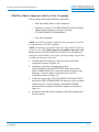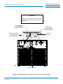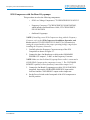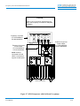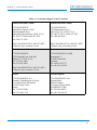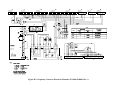
1
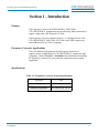
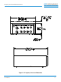
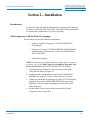
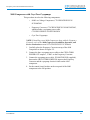
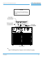
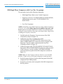
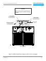
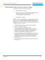
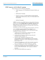
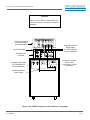
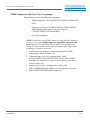
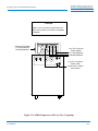
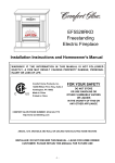
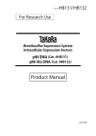
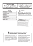
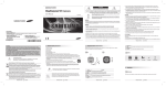
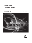
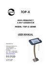
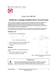
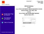
CTI- CRYOGENICS
HELIX TECHNOLOGY CORPORATION
Frequency Converter Installation
Instructions
8040520
Rev. A (2/98)
View our inventory
HELIX TECHNOLOGY CORPORATION
Mansfield Corporate Center, Nine Hampshire Street, Mansfield, Massachusetts 02048-9171 Telephone (508) 337-5000
The information in this document is believed to be accurate and reliable. However,
CTI-CRYOGENICS - Helix Technology Corporation, cannot accept any financial or other
responsibilities that may result from the use of this information. No warranties are granted or
extended by this document.
CTI-CRYOGENICS - Helix Technology Corporation reserves the right to change any or all
information contained herein without prior written notice. Revisions may be issued at the time of
such changes and/or deletions.
Any duplication of this manual or any of its parts without expressed written permission from
CTI-CRYOGENICS - Helix Technology Corporation is strictly prohibited.
Any correspondence regarding this document should be forwarded to:
CTI-CRYOGENICS
Helix Technology Corporation
Mansfield Corporate Center
Engineering Services Department
Nine Hampshire Street
Mansfield, Massachusetts 02048-9171 U.S.A.
Telephone: (508) 337-5000
FAX: (508) 337-5464
The following CTI-CRYOGENICS - Helix Technology Corporation trademarks and service
marks may appear in this document:
CTI-CRYOGENICS®
Cryo-Torr®
On-Board®
Value Line™
FastRegen™
TurboLink™
ThinLine™
GUTS®
Cryodyne®
RetroFast®
RetroEase®
TurboPlus™
All other trademarks or registered trademarks are the property of their respective holders.
Copyright© 1998 CTI-CRYOGENICS - Helix Technology Corporation
Printed in U.S.A.
CTI- CRYOGENICS
Frequency Converter Installation Instructions
HELIX TECHNOLOGY CORPORATION
Table of Contents
Section 1 - Introduction
Purpose . . . . . . . . . . . . . . . . . . . . . . . . . . . . . . . . . . . . . . . . . . . . . . . . . . . . . . . . . . . 1-1
Frequency Converter Applications . . . . . . . . . . . . . . . . . . . . . . . . . . . . . . . . . . . . . 1-1
Specifications . . . . . . . . . . . . . . . . . . . . . . . . . . . . . . . . . . . . . . . . . . . . . . . . . . . . . . 1-1
Section 2 - Installation
Introduction . . . . . . . . . . . . . . . . . . . . . . . . . . . . . . . . . . . . . . . . . . . . . . . . . . . . . . . 2-1
9600 Compressor with On-Board Cryopumps . . . . . . . . . . . . . . . . . . . . . . . . . . . . 2-1
9600 Compressor with Cryo-Torr Cryopumps . . . . . . . . . . . . . . . . . . . . . . . . . . . . 2-3
8200 Single Phase Compressor with an On-Board Cryopump . . . . . . . . . . . . . . . . 2-5
8200 Single Phase Compressor with Cryo-Torr Cryopumps . . . . . . . . . . . . . . . . . 2-7
8200 Three Phase Compressor with an On-Board Cryopump . . . . . . . . . . . . . . . . 2-9
8200 Three Phase Compressor with Cryo-Torr Cryopumps . . . . . . . . . . . . . . . . . 2-11
8510 Compressor with On-Board Cryopumps . . . . . . . . . . . . . . . . . . . . . . . . . . . 2-13
8500 Compressor with On-Board Cryopumps . . . . . . . . . . . . . . . . . . . . . . . . . . . 2-15
8500 Compressor with Cryo-Torr Cryopumps . . . . . . . . . . . . . . . . . . . . . . . . . . . 2-17
1020R Compressor with On-Board Cryopumps . . . . . . . . . . . . . . . . . . . . . . . . . . 2-19
1020R Compressor with Cryo-Torr Cryopumps . . . . . . . . . . . . . . . . . . . . . . . . . . 2-21
Appendix A - Customer Support Centers
Appendix B - Drawings
P/N 8040520
iii
CTI- CRYOGENICS
Frequency Converter Installation Instructions
HELIX TECHNOLOGY CORPORATION
Table of Contents (continued)
Figures
Figure 1-1: Frequency Converter Chassis Front and Rear Views . . . . . . . . . . . 1-2
Figure 1-2: Frequency Converter Dimensions . . . . . . . . . . . . . . . . . . . . . . . . . . 1-3
Figure 2-1: 9600 LV Compressor with On-Board Cryopumps . . . . . . . . . . . . . 2-2
Figure 2-2: 9600 LV Compressor with an Cryo-Torr Cryopumps . . . . . . . . . . 2-4
Figure 2-3: 8200 Single Phase Compressor with an On-Board Cryopump . . . . 2-6
Figure 2-4: 8200 for Single Phase Compressor with Cryo-Torr Cryopumps . . 2-8
Figure 2-5: 8200 Three-Phase Compressor with an On-Board Cryopump . . . 2-10
Figure 2-6: 8200 Three-Phase Compressor with Cryo-Torr Cryopumps . . . . 2-12
Figure 2-7: 8510 Compressor with On-Board Cryopumps . . . . . . . . . . . . . . . 2-14
Figure 2-8: 8500 Compressor with an On-Board Cryopump . . . . . . . . . . . . . 2-16
Figure 2-9: 8500 Compressor with Cryo-Torr Cryopumps . . . . . . . . . . . . . . . 2-18
Figure 2-10: 1020R Compressor with On-Board Cryopumps . . . . . . . . . . . . . 2-20
Figure 2-11: 1020R Compressor with Cryo-Torr Cryopumps . . . . . . . . . . . . 2-22
Figure B-1: Frequency Converter Electrical Schematic
P/N 8043194P001 Rev. A . . . . . . . . . . . . . . . . . . . . . . . . . . . . . . . . B-2
Tables
Table 1-1:Frequency Converter General Specifications . . . . . . . . . . . . . . . . . . 1-1
Table A-1:Customer Support Center Locations . . . . . . . . . . . . . . . . . . . . . . . A-2
P/N 8040520
iv
CTI- CRYOGENICS
Frequency Converter Installation Instructions
HELIX TECHNOLOGY CORPORATION
Section 1 - Introduction
Purpose
The Frequency Converter, P/N 8043202G001 - G005 allows
CTI-CRYOGENICS’ equipment to operate efficiently when connected to a
supply voltage with a line frequency of 50Hz.
The Frequency Converter, shown in Figure 1-1, is designed for use with
CTI-CRYOGENICS’ 9600, 8200, 8510, 8500, and 1020R compressors,
and On-Board and Cryo-Torr Cryopumps.
Frequency Converter Applications
There are different configurations of the Frequency Converter to
support various configurations of CTI-CRYOGENICS’ compressors and
cryopumps. Refer to Section 2 - Installation for information on installing
the Frequency Converter for your particular compressor and cryopump
application.
Specifications
Table 1-1: Frequency Converter General Specifications
P/N 8040520
Parameter
Value
Weight
50 lbs (22.67 kg)
Ambient Temperature
50 - 100 º F (10 - 38 º C)
1-1
CTI- CRYOGENICS
Frequency Converter Installation Instructions
HELIX TECHNOLOGY CORPORATION
Front Panel View
LT1
COMPRESSOR
REMOTE
CRYO-TORR®
POWER IN
1
CRYO-TORR® POWER OUT
3
2
CUSTOMER
REMOTE
ON-BOARD®
POWER IN
1
ON-BOARD® POWER OUT
2
3
Rear Panel View
Figure 1-1: Frequency Converter Chassis Front and Rear Views
P/N 8040520
1-2
Frequency Converter Installation Instructions
CTI- CRYOGENICS
HELIX TECHNOLOGY CORPORATION
Figure 1-2: Frequency Converter Dimensions
P/N 8040520
1-3
Frequency Converter Installation Instructions
CTI- CRYOGENICS
HELIX TECHNOLOGY CORPORATION
Section 2 - Installation
Introduction
Section 2 provides all required information for connecting the Frequency
Converter to the 9600, 8200, 8510, 8500, and 1020R Compressors which
are connected to On-Board or Cryo-Torr Cryopumps.
9600 Compressor with On-Board Cryopumps
This procedure involves the following components:
•
9600 Low-Voltage Compressor, CTI-CRYOGENICS P/N
8135900G001
•
Frequency Converter, CTI-CRYOGENICS P/N 8043202G002,
which includes On-Board Power Cable, CTI-CRYOGENICS
P/N 8112463G050
•
On-Board Cryopumps
NOTE: If installing a new 9600 Compressor along with the Frequency
Converter, refer to the 9600 Compressor Installation, Operation, and
Service Instructions manual CTI-CRYOGENICS P/N 8040444.
1. Carefully place the Frequency Converter on top of the 9600
Compressor as shown in Figure 2-1.
2. Connect the three On-Board power cables to the ON-BOARD
POWER OUT outputs 1, 2 and 3 on the Frequency Converter.
3. Connect the On-Board Cryopump power cable, P/N 8112463G050
(supplied), between the ON-BOARD POWER IN, input on the
Frequency Converter and the cryopump electrical outlet on the
9600 compressor.
4. Set the control circuit breaker on the rear panel of the 9600
compressor to the ON position.
P/N 8040520
2-1
CTI- CRYOGENICS
Frequency Converter Installation Instructions
HELIX TECHNOLOGY CORPORATION
CAUTION
Allow a 1.0 inch minimum space above the
top of the Frequency Converter for adequate
ventilation
Frequency Converter
CTI-CRYOGENICS
P/N 8043202G002
On-Board Cryopump
Power Cables
CTI-CRYOGENICS
P/N 8112463GXXX
Figure 2-1: 9600 LV Compressor with On-Board Cryopumps
P/N 8040520
2-2
Frequency Converter Installation Instructions
CTI- CRYOGENICS
HELIX TECHNOLOGY CORPORATION
9600 Compressor with Cryo-Torr Cryopumps
This procedure involves the following components:
•
9600 Low-Voltage Compressor, CTI-CRYOGENICS P/N
8135900G001
•
Frequency Converter, CTI-CRYOGENICS P/N 8043202G005,
which includes a cryopump power cable,
CTI-CRYOGENICS P/N 8043209G050
•
Cryo-Torr Cryopumps
NOTE: If installing a new 9600 Compressor along with the Frequency
Converter, refer to the 9600 Compressor Installation, Operation, and
Service Instructions manual CTI-CRYOGENICS P/N 8040444.
1. Carefully place the Frequency Converter on top of the 9600
Compressor as shown in Figure 2-2.
2. Connect the three cryopump power cables to the CRYO-TORR
POWER OUT outputs 1, 2 and 3 on the Frequency Converter.
3. Connect the cryopump power cable, P/N 8043209G050 (supplied),
between the CRYO-TORR POWER IN, input on the Frequency
Converter and the cryopump electrical outlet on the 9600
compressor.
4. Set the control circuit breaker on the rear panel of the 9600
compressor to the ON position.
P/N 8040520
2-3
CTI- CRYOGENICS
Frequency Converter Installation Instructions
HELIX TECHNOLOGY CORPORATION
CAUTION
Allow a 1.0 inch minimum space above the
top of the Frequency Converter for adequate
ventilation
Power Cable
CTI-CRYOGENICS
P/N 8032222GXXX
Frequency Converter
CTI-CRYOGENICS
P/N 8043202G005
To Cryo-Torr
Cryopumps
9600 to Frequency
Converter Power Cable
CTI-CRYOGENICS
P/N 8043209G050
Figure 2-2: 9600 LV Compressor with an Cryo-Torr Cryopumps
P/N 8040520
2-4
Frequency Converter Installation Instructions
CTI- CRYOGENICS
HELIX TECHNOLOGY CORPORATION
8200 Single Phase Compressor with an On-Board Cryopump
This procedure involves the following components:
•
8200 Single Phase, Water or Air Cooled Compressor
•
Frequency Converter, CTI-CRYOGENICS P/N 8043202G004,
which includes power cable CTI-CRYOGENICS P/N
8043071G050
•
One On-Board Cryopump
NOTE: If installing a new 8200 Compressor along with the Frequency
Converter, refer to the 8200 Compressor Installation, Operation, and
Service manual CTI-CRYOGENICS P/N 8040353 for information on
setting the control module to the proper operating voltage range before
installing the Frequency Converter.
1. Carefully place the Frequency Converter on top of the 8200
Compressor as shown in Figure 2-3.
2. Connect the On-Board Cryopump power cable
CTI-CRYOGENICS P/N8112463GXXX between one of the
ON-BOARD POWER OUT connectors on the rear panel of the
Frequency Converter and the POWER IN connector on the
On-Board Cryopump Module.
3. Connect the power cable CTI-CRYOGENICS P/N 8043071G050
between the ON-BOARD POWER IN connector on the rear panel
of the Frequency Converter and the ON-BOARD POWER
connector on the rear panel of the 8200 compressor as shown in
Figure 2-3.
NOTE: Make sure the Frequency Selector Switch is set to the 60Hz
position. Failure to do so will result in improper system operation.
4. Set the Frequency Selector Switch on the front panel of the 8200
compressor to the 60Hz position.
5. Set the Power Switch on the front panel of the 8200 compressor to
the ON position.
P/N 8040520
2-5
CTI- CRYOGENICS
Frequency Converter Installation Instructions
HELIX TECHNOLOGY CORPORATION
CAUTION
Allow a 1.0 inch minimum space above the
top of the Frequency Converter for adequate
ventilation
Power Cable
CTI-CRYOGENICS
P/N 8043071G050
Frequency Converter
CTI-CRYOGENICS
P/N 8043202G004
Power Cable
CTI-CRYOGENICS
P/N 8112463GXXX
8200 Compressor
Figure 2-3: 8200 Single Phase Compressor with an On-Board Cryopump
P/N 8040520
2-6
Frequency Converter Installation Instructions
CTI- CRYOGENICS
HELIX TECHNOLOGY CORPORATION
8200 Single Phase Compressor with Cryo-Torr Cryopumps
This procedure involves the following components:
•
8200 Single Phase, Water or Air Cooled Compressor
•
Frequency Converter, CTI-CRYOGENICS P/N 8043202G003,
which includes power cable CTI-CRYOGENICS P/N
8043072G050
•
Cryo-Torr Cryopumps
NOTE: If installing a new 8200 Compressor along with the Frequency
Converter, refer to the 8200 Compressor Installation, Operation, and
Service manual CTI-CRYOGENICS P/N 8040353 for information on
setting the control module to the proper operating voltage range before
installing the Frequency Converter.
1. Carefully place the Frequency Converter on top of the 8200
Compressor as shown in Figure 2-4.
2. Connect the Cryo-Torr Cryopump power cable
CTI-CRYOGENICS P/N 8032222GXXX between one of the
CRYO-TORR POWER OUT connectors on the rear panel of the
Frequency Converter and the connector on the Cryo-Torr
Cryopump as shown in Figure 2-4.
3. Connect the power cable CTI-CRYOGENICS P/N 8043072G050
between the CRYO-TORR POWER IN connector on the rear panel
of the Frequency Converter and the COLD HEAD POWER
connector on the rear panel of the 8200 compressor as shown in
Figure 2-4.
NOTE: Make sure the Frequency Selector Switch is set to the 60Hz
position. Failure to do so will result in improper system operation.
4. Set the Frequency Selector Switch on the front panel of the 8200
compressor to the 60Hz position.
5. Set the Power Switch on the front panel of the 8200 compressor to
the ON position.
P/N 8040520
2-7
CTI- CRYOGENICS
Frequency Converter Installation Instructions
HELIX TECHNOLOGY CORPORATION
CAUTION
Allow a 1.0 inch minimum space above the
top of the Frequency Converter for adequate
ventilation
Power Cable
CTI-CRYOGENICS
P/N 8043072G050
Power Cable
CTI-CRYOGENICS
P/N 8032222GXXX
To Cryo-Torr
Cryopump
Frequency Converter
CTI-CRYOGENICS
P/N 8043202G003
8200 Compressor
Figure 2-4: 8200 for Single Phase Compressor with Cryo-Torr Cryopumps
P/N 8040520
2-8
Frequency Converter Installation Instructions
CTI- CRYOGENICS
HELIX TECHNOLOGY CORPORATION
8200 Three Phase Compressor with an On-Board Cryopump
This procedure involves the following components:
•
8200 Three Phase Compressor
•
Frequency Converter, CTI-CRYOGENICS P/N 8043202G002,
which includes On-Board Cryopump power cable
CTI-CRYOGENICS P/N 8112463G050
•
One On-Board Cryopump
NOTE: If installing a new 8200 Compressor along with the Frequency
Converter, refer to the 8200 Compressor Installation, Operation, and
Service manual CTI-CRYOGENICS P/N 8040353 for information on
setting the control module to the proper operating voltage range before
installing the Frequency Converter.
1. Carefully place the Frequency Converter on top of the 8200
Compressor as shown in Figure 2-5.
2. Connect the On-Board Cryopump power cable
CTI-CRYOGENICS P/N 8112463GXXX between one of the
ON-BOARD POWER OUT connectors on the rear panel of the
Frequency Converter and the POWER IN connector on the
On-Board Cryopump Module as shown in Figure 2-5.
3. Connect the power cable CTI-CRYOGENICS P/N 8112463G050
(supplied) between the ON-BOARD POWER IN connector on the
rear panel of the Frequency Converter and the ON-BOARD
POWER connector on the rear panel of the 8200 compressor as
shown in Figure 2-5.
4. Set the Power Switch on the front panel of the 8200 compressor to
the ON position.
P/N 8040520
2-9
CTI- CRYOGENICS
Frequency Converter Installation Instructions
HELIX TECHNOLOGY CORPORATION
CAUTION
Allow a 1.0 inch minimum space above the
top of the Frequency Converter for adequate
ventilation
Power Cable
CTI-CRYOGENICS
P/N 8112463G050
Power Cable
CTI-CRYOGENICS
P/N 8112463GXXX
Frequency Converter
CTI-CRYOGENICS
P/N 8043202G002
To On-Board
Cryopump
8200 Compressor
Figure 2-5: 8200 Three-Phase Compressor with an On-Board Cryopump
P/N 8040520
2-10
Frequency Converter Installation Instructions
CTI- CRYOGENICS
HELIX TECHNOLOGY CORPORATION
8200 Three Phase Compressor with Cryo-Torr Cryopumps
This procedure involves the following components:
•
8200 Three Phase Water Cooled Compressor
•
Frequency Converter, CTI-CRYOGENICS P/N 8043202G001,
which includes Frequency Converter Cable Kit,
CTI-CRYOGENICS P/N 8080005K012
•
Cryo-Torr Cryopumps
NOTE: An 8200 Three Phase Compressor does not support Cryo-Torr
Cryopump Remote ON/OFF capability.
NOTE: If installing a new 8200 Compressor along with the Frequency
Converter, refer to the 8200 Compressor Installation, Operation, and
Service manual CTI-CRYOGENICS P/N 8040353 for information on
setting the control module to the proper operating voltage range before
installing the Frequency Converter.
1. Carefully place the Frequency Converter on top of the 8200
Compressor as shown in Figure 2-6.
2. Connect the Cryo-Torr Cryopump power cable
CTI-CRYOGENICS P/N 8032222GXXX between one of the
CRYO-TORR POWER OUT connectors on the rear panel of the
Frequency Converter and the connector on the Cryo-Torr
Cryopump as shown in Figure 2-6.
3. Connect the power cable CTI-CRYOGENICS P/N 8043054G050
between the CRYO-TORR POWER IN connector on the rear panel
of the Frequency Converter and the COLD HEAD POWER
connector on the rear panel of the 8200 compressor as shown in
Figure 2-6.
4. Set the Power Switch on the front panel of the 8200 compressor to
the ON position.
P/N 8040520
2-11
CTI- CRYOGENICS
Frequency Converter Installation Instructions
HELIX TECHNOLOGY CORPORATION
CAUTION
Allow a 1.0 inch minimum space above the
top of the Frequency Converter for adequate
ventilation
Power Cable
CTI-CRYOGENICS
P/N 8043054G050
Power Cable
CTI-CRYOGENICS
P/N 8032222GXXX
To Cryo-Torr
Cryopump
Frequency Converter
CTI-CRYOGENICS
P/N 8043202G001
8200 Compressor
Figure 2-6: 8200 Three-Phase Compressor with Cryo-Torr Cryopumps
P/N 8040520
2-12
Frequency Converter Installation Instructions
CTI- CRYOGENICS
HELIX TECHNOLOGY CORPORATION
8510 Compressor with On-Board Cryopumps
This procedure involves the following components:
•
8510 Low-Voltage Compressor, CTI-CRYOGENICS P/N 8031315
•
Frequency Converter, CTI-CRYOGENICS P/N 8043202G002,
which includes On-Board Power Cable, CTI-CRYOGENICS
P/N 8112463G050
•
On-Board Cryopumps
NOTE: If installing a new 8510 Compressor along with the Frequency
Converter, refer to the 8510 Compressor Installation, Operation, and
Service manual CTI-CRYOGENICS P/N 8040232 for information on
setting the control module to the proper operating voltage range before
installing the Frequency Converter.
1. Carefully place the Frequency Converter on top of the 8510
Compressor as shown in Figure 2-7.
2. Connect the three On-Board power cables to the ON-BOARD
POWER OUT outputs 1, 2 and 3 on the Frequency Converter.
NOTE: Make sure the On-Board Cryopump Power cable is connected to
COLD HEAD 3 output on the compressor in step 3. The CUSTOMER
REMOTE capability will not function if connected to output 1 or 2.
3. Connect the On-Board Cryopump power cable, P/N 8112463G050
(supplied), between the ON-BOARD POWER IN, input on the
converter and the COLD HEAD 3 output on the compressor.
4. Set the Power Switch on the front panel of the 8510 compressor to
the ON position.
P/N 8040520
2-13
CTI- CRYOGENICS
Frequency Converter Installation Instructions
HELIX TECHNOLOGY CORPORATION
CAUTION
Allow a 1.0 inch minimum space above the
top of the Frequency Converter for adequate
ventilation
Frequency Converter
CTI-CRYOGENICS
P/N 8043202G002
On-Board Cryopump
Power Cables
CTI-CRYOGENICS
P/N 8112463GXXX
Frequency Converter
Power Cable
CTI-CRYOGENICS
P/N 8112463G050
NOTE: Must be
connected to COLD
HEAD 3 connector to
support remote option.
8510 Compressor
Figure 2-7: 8510 Compressor with On-Board Cryopumps
P/N 8040520
2-14
Frequency Converter Installation Instructions
CTI- CRYOGENICS
HELIX TECHNOLOGY CORPORATION
8500 Compressor with On-Board Cryopumps
This procedure involves the following components:
•
8500 Compressor, CTI-CRYOGENICS P/N 8031348G001 or G002
•
Frequency Converter, CTI-CRYOGENICS P/N 8043202G002,
which includes Frequency Converter Cable Kit,
CTI-CRYOGENICS P/N 8080005K012 8011 Compressor
Controller
•
On-Board Cryopumps
NOTE: If installing a new 8500 Compressor along with the Frequency
Converter, refer to the 8500 Compressor Installation, Operation, and
Service manual CTI-CRYOGENICS P/N 8040324 for information on
setting the control module to the proper operating voltage range before
installing the Frequency Converter.
If installing a new 8011 Controller along with the Frequency Converter,
refer to the 8011 Controller and 8011 Control Module manual
CTI-CRYOGENICS P/N 8040309 for proper setup before installing the
Frequency Converter.
1. Carefully place the 8011 Controller on top of the 8500 compressor as shown in Figure 2-8.
2. Carefully place the Frequency Converter on top of the 8011
Controller as shown in Figure 2-8.
NOTE: Make sure the cryopump cable is connected to COLD HEAD 3
output on the compressor. The CUSTOMER REMOTE capability will not
function if connected to output 1 or 2.
3. Connect the cryopump cable CTI-CRYOGENICS
P/N 8043054P050 between COLD HEAD 3 connector on the 8500
Compressor and 1 IN connector on the 8011 Controller.
4. Connect the On-Board power cable CTI-CRYOGENICS
P/N 8112463G050 between the 1 OUT connector on the 8011
Controller and the ON-BOARD POWER IN connector on the
Frequency Converter.
5. Connect the On-Board Cryopump power cables
CTI -CRYOGENICS P/N 8112463GXXX between the
ON-BOARD POWER OUT connectors on the Frequency
Converter and the On-Board Cryopumps.
P/N 8040520
2-15
CTI- CRYOGENICS
Frequency Converter Installation Instructions
HELIX TECHNOLOGY CORPORATION
6. Set the Power Switch on the front panel of the 8500 compressor to
the ON position.
CAUTION
Allow a 1.0 inch minimum space above the
top of the Frequency Converter for adequate
ventilation
Frequency Converter
CTI-CRYOGENICS
P/N 8043202G002
On-Board 8011
Controller
On-Board Cryopump
Power Cables
CTI-CRYOGENICS
P/N 8112463GXXX
INPUT
POWER
IN
IN
IN
COMPRESSOR
POWER
Input Power Cable
OUT
OUT
OUT
On-Board Cryopump
Power Cables
CTI-CRYOGENICS
P/N 8112463G050
8500 Compressor
Power Cable
Cryopump Cable
CTI-CRYOGENICS
P/N 8043054P050
8500
Compressor
Figure 2-8: 8500 Compressor with an On-Board Cryopump
P/N 8040520
2-16
Frequency Converter Installation Instructions
CTI- CRYOGENICS
HELIX TECHNOLOGY CORPORATION
8500 Compressor with Cryo-Torr Cryopumps
This procedure involves the following components:
•
8500 Compressor, CTI-CRYOGENICS P/N 8031348G001 or G002
•
Frequency Converter, CTI-CRYOGENICS P/N 8043202G001,
which includes Frequency Converter Cable Kit,
CTI-CRYOGENICS P/N 8080005K012 which can be used with an
optional remote
•
Cryo-Torr Cryopumps
NOTE: If installing a new 8500 Compressor along with the Frequency
Converter, refer to the 8500 Compressor Installation, Operation, and
Service manual CTI-CRYOGENICS P/N 8040324 for information on
setting the control module to the proper operating voltage range before
installing the Frequency Converter.
1. Carefully place the Frequency Converter on top of the 8500
Compressor as shown in Figure 2-9.
2. Connect the cables to the corresponding CRYO-TORR POWER
outputs 1, 2 and 3 on the Frequency Converter.
3. Connect the standard remote cable between the COMPRESSOR
REMOTE input on the converter and the REMOTE input on the
compressor (optional).
4. Connect the Power Cable between the CRYO-TORR POWER IN
input on the converter and the COLD HEAD 3 output on the
compressor.
NOTE: Make sure the cryopump cable is connected to COLD HEAD 3
output on the compressor. The CUSTOMER REMOTE capability will not
function if connected to output 1 or 2.
5. Set the Power Switch on the front panel of the 8500 compressor to
the ON position.
P/N 8040520
2-17
CTI- CRYOGENICS
Frequency Converter Installation Instructions
HELIX TECHNOLOGY CORPORATION
CAUTION
Allow a 1.0 inch minimum space above the
top of the Frequency Converter for adequate
ventilation
Frequency Converter
CTI-CRYOGENICS
P/N 8043202G001
Cryo-Torr Cryopump
Power Cables
CTI-CRYOGENICS
P/N 8032222GXXX
Standard Remote Cable
CTI-CRYOGENICS
P/N 8043042P050
(optional)
Frequency Converter
Power Cable
CTI-CRYOGENICS
P/N 8043054G050
NOTE: Must be
connected to COLD
HEAD 3 connector to
support remote option.
8500
Compressor
Figure 2-9: 8500 Compressor with Cryo-Torr Cryopumps
P/N 8040520
2-18
Frequency Converter Installation Instructions
CTI- CRYOGENICS
HELIX TECHNOLOGY CORPORATION
1020R Compressor with On-Board Cryopumps
This procedure involves the following components:
•
1020R Compressor, CTI-CRYOGENICS P/N 8031023G001 and
G002
•
On-Board 8011 Controller
•
Frequency Converter, CTI-CRYOGENICS P/N 8043202G002
which includes On-Board Power Cable, CTI-CRYOGENICS P/N
8112463G050
•
On-Board Cryopumps
NOTE: If installing a new 1020R Compressor along with the Frequency
Converter, refer to the 1020R Compressor Installation, Operation, and
Service manual CTI-CRYOGENICS P/N 8040274 for information on
setting the control module to the proper operating voltage range before
installing the Frequency Converter.
If installing a new 8011 Controller along with the Frequency Converter,
refer to the 8011 Controller and 8011 Control Module manual
CTI-CRYOGENICS P/N 8040309 for proper setup information before
installing the Frequency Converter.
1. Carefully place the On-Board 8011 Controller on top of the
1020R Compressor as shown in Figure 2-10.
2. Carefully place the Frequency Converter on top of the 8011
Controller as shown in Figure 2-10.
3. Connect the three On-Board cryopump power cables
CTI-CRYOGENICS P/N 81122463GXXX into the ON-BOARD
POWER OUT connectors 1, 2 and 3 on the Frequency Converter as
shown in Figure 2-10.
4. Connect the cryopump power cable, hard wired to the compressor,
to the COLD HEADS 1 IN connector on the 8011 Controller.
5. Connect the On-Board power cable, CTI-CRYOGENICS P/N
8112463G050 (supplied) to the On-Board POWER IN input on the
converter and the CRYOPUMPS 1 OUT connector on the 8011
Controller.
6. Turn on SYSTEM POWER at the compressor.
P/N 8040520
2-19
CTI- CRYOGENICS
Frequency Converter Installation Instructions
HELIX TECHNOLOGY CORPORATION
CAUTION
Allow a 1.0 inch minimum space above the
top of the Frequency Converter for adequate
ventilation
Frequency Converter
CTI-CRYOGENICS
P/N 8043202G002
Input Power Cable
On-Board 8011
Controller
On-Board Power Cable
CTI-CRYOGENICS
P/N 8112463G050
On-Board Cryopump
Power Cables
CTI-CRYOGENICS
P/N 8112463GXXX
INPUT
POWER
IN
IN
IN
OUT
OUT
OUT
COMPRESSOR
POWER
On-Board Cryopump
Power Cable
(Hard wired to 1020R
Compressor)
1020R Compressor
Power Cable
Figure 2-10: 1020R Compressor with On-Board Cryopumps
P/N 8040520
2-20
Frequency Converter Installation Instructions
CTI- CRYOGENICS
HELIX TECHNOLOGY CORPORATION
1020R Compressor with Cryo-Torr Cryopumps
This procedure involves the following components:
•
1020R Compressor, CTI-CRYOGENICS P/N 8031023G001 and
G002
•
Frequency Converter, CTI-CRYOGENICS P/N 8043202G001,
which includes the Frequency Converter Cable Kit
CTI-CRYOGENICS P/N 8080005K012
•
Cryo-Torr Cryopumps
NOTE: If installing a new 1020R Compressor along with the Frequency
Converter, refer to the 1020R Compressor Installation, Operation, and
Service manual CTI-CRYOGENICS P/N 8040274 for information on
setting the control module to the proper operating voltage range before
installing the Frequency Converter.
1. Carefully place the Frequency Converter on top of the 1020R
Compressor as shown in Figure 2-11.
2. Connect the three Cryo-Torr cryopump power cables
CTI-CRYOGENICS P/N 8032222GXXX into the CRYO-TORR
POWER OUT connectors 1, 2 and 3 on the Frequency Converter as
shown in Figure 2-11.
3. Connect the Cryo-Torr Cryopump Power Cable to the
CRYO-TORR POWER IN connector on the Frequency Converter.
4. Turn on SYSTEM POWER at the compressor.
P/N 8040520
2-21
CTI- CRYOGENICS
Frequency Converter Installation Instructions
HELIX TECHNOLOGY CORPORATION
CAUTION
Allow a 1.0 inch minimum space above the
top of the Frequency Converter for adequate
ventilation
Frequency Converter
CTI-CRYOGENICS
P/N 8043202G001
Cryo-Torr Cryopump
Power Cables
CTI-CRYOGENICS
P/N 8032222GXXX
Cryo-Torr Cryopump
Power Cable
(Hard wired to 1020R
Compressor)
Figure 2-11: 1020R Compressor with Cryo-Torr Cryopumps
P/N 8040520
2-22
CTI- CRYOGENICS
Appendix A - Customer Support Centers
HELIX TECHNOLOGY CORPORATION
Appendix A - Customer Support Centers
Introduction
Refer to Table A-1 for the nearest Customer Support Center for technical
assistance or service. North American customers may call
1-800-FOR-GUTS (1-800-367-4887) 24 hours a day, seven days a week.
All other customers must call their local Customer Support Center.
Please have the following information available when calling so that we
may assist you:
•
Product Part Number
•
Product Serial Number
•
Product Application
•
Specific Problem Area
•
Hours of Operation
•
Equipment Type
•
Vacuum System Brand/Model/Date of Manufacture
A-1
CTI- CRYOGENICS
Appendix A - Customer Support Centers
HELIX TECHNOLOGY CORPORATION
Table A-1: Customer Support Center Locations
United States and Canada
United States and Canada
CTI-CRYOGENICS
Mansfield Corporate Center
Nine Hampshire Street
Mansfield, Massachusetts 02048, U.S.A.
Tel: 508-337-5000 or 800-447-5007
Fax: 508-337-5169
CTI-CRYOGENICS
3350 Montgomery Drive
Santa Clara, CA 95054, U.S.A.
Tel: 408-727-8077 or 800-447-5007
Fax: 408-988-6630
Dial 1-800-FOR-GUTS (1-800-367-4887)
24 hours a day, seven days a week.
Dial 1-800-FOR-GUTS (1-800-367-4887)
24 hours a day, seven days a week.
United States and Canada
Germany
CTI-CRYOGENICS
4120 Freidrich Lane, Suite 600
Austin, TX 78744, U.S.A.
Tel: 512-912-2800
Fax: 512-912-2888
CTI-CRYOGENICS, GmbH
Haasstrasse 15
D-64293 Darmstadt
Germany
Tel: 49-6151-871377
Fax: 49-6151-891635
Dial 1-800-FOR-GUTS (1-800-367-4887)
24 hours a day, seven days a week.
France
United Kingdom
CTI-CRYOGENICS, SA
Domaine Technologique de Saclay
4, rue Rene Razel, Bat Apollo
F-91892 Orsay Cedex
France
Tel: 331-6935-2600
Fax: 331-6985-3725
CTI-CRYOGENICS Ltd.
Fleming Road
Kirkton Campus
Livingston, West Lothian
Scotland EH54 7BN
Tel: 441-506-460017
Fax: 441-506-411122
A-2
CTI- CRYOGENICS
Appendix A - Customer Support Centers
HELIX TECHNOLOGY CORPORATION
Table A-1: Customer Support Center Locations (Continued)
Japan
Korea
CTI-CRYOGENICS
Daido Hoxan Engineering Co., Ltd.
1-8, Nakahama-cho
Amagasaki-shi
Hyogo
660 Japan
Tel: 81-6-412-5071
Fax: 81-6-412-7408
CTI-CRYOGENICS
Zeus Company, Ltd.
Zeus Building
3-16, Yangjae-Dong, Sochu-Ku
Seoul, 137-130
South Korea
Tel: 82-2-577-3181
Tel: 82-2-577-3186
Fax: 82-2-576-3199
Taiwan, Hong Kong, and China
Australia, New Zealand, and Tasmania
CTI-CRYOGENICS
Challentech International Corporation
No. 1, Lane 9, Pateh Road
Hsin-Chu
300, Taiwan, R.O.C.
Tel: 886-35-614211
Fax: 886-35-614210
CTI-CRYOGENICS
AVT Services Pte. Ltd
Unit 1, 12 Pioneer Avenue
Thornleigh NSW 2120
Sydney, Australia
Tel: 612-9-4810748
Fax: 612-9-4810910
Singapore, Malaysia, Philippines, and
Indonesia
CTI-CRYOGENICS
APP Systems Services Pte Ltd..
2 Corporation Road
#06-14 Corporation Place
Singapore 2261
Tel: 65-268-2024
Fax: 65-268-6621
A-3
CTI- CRYOGENICS
Appendix B - Drawings
HELIX TECHNOLOGY CORPORATION
Appendix B - Drawings
Drawing Title
Frequency Converter Schematic
B-1
Drawing Number
Page
P/N 8043194P001
B-2
P/N 8040520
Figure B-1: Frequency Converter Electrical Schematic P/N 8043194P001 Rev. A