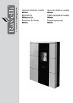
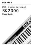
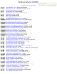
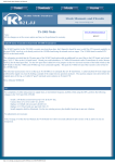
1
KB2LJJ Radio Mods Database
KB2LJJ
Radio Mods Database and Manuals
Home
Modifications for the Kenwood TM-731 and TM 731 A/E
TM-731 frequency and cross band repeater
TM731 & 9600 Bps
TM-731 fuer 9600 Baud
TM-731A Hooking to TNCS
Kenwood Cross Band Repeat: How to USE
it
Kenwood TM-731A firmware bug
TM-631/731A Memory loss modification
TM-731A/631A Final board C17 change
TM-731e Frequenz erweiterung
For the TM-731A, there is a "Beyond MARS/CAP transmit Modification".
It provides TX from 136 to 174 and 400 to 500 MHz. Again, actual TX range limited
by PLL tuning. If you don't already have this and would like it, I'll
send a copy if you furnish me your address. It involves cutting R25 on the
control unit, and installing a jumper (diagram required to locate position),
then two resets in a row.
I have tested these mods on my own rigs.
http://www.kb2ljj.com/data/kenwood/TM-731A.htm (1 di 18)30/08/2009 18.40.45
www.r6-ru4montesecchieta.it
IZ5CCV
KB2LJJ Radio Mods Database
TM-731 frequency and cross band repeater
The TM-731a will transcive between 136-174 MHz and 400-500 MHz as well as perform cross band repeter function when
the following modifications are performed.
1. Remove both the top and bottom cover. Disassemble the front panel such that the control unit (X53-3250-XX) is
accessable.
2. Remove R121, R123 and R25. While R125 snd R124 must be present.
3. If the time-out timer function is not desired, remouve R122 as well.
4. Reassemble the unit and perform a microprocessor reset before operating the set.
5. Preserve your license by operating whithin the bands it is cover for.
TM731 & 9600 Bps
The TM731 is different enought to cause problems.
What need to be done is to add another RX Mute transistor. (look the schematics and see how the TX deviation is shorted
to ground during receive.)
Use a plain NPN and a pair of 10k resistor (copy the one used on VR3 in the schematics.)
Take the TX DATA and feed it to the collector through a series 1k resistor, and then feed that through another 1k resistor to
the wiper on the deviator pot.
This was a result of Kenwood changing the deviation pot value from 10k to 100k (it's wasn't broken, but they fixed it
anyway.) It is full of surface mount devices.
Article of Jeff WA6FWI @ WB6YMH.#SOCA.CA
From: CQ USA - June/92
TM-731 fuer 9600 Baud
German language
de DG5EM @ DB0IZ
Umbaumassnahmen beim TM 731 von Kenwood zum betrieb mit G3RUH-Modem 9600 Baud
Das Geraet von der Seite oben die Platte abschrauben, wo sich auf dem rueckseitigen Kuehlkoerper die Blindbuchse mit
Stopfen befindet.
Kontrollieren ob man wirklich die 430er-UNIT vor sich hat hi.
Diesen Stopfen entfernen und das Loch als Eingang fuer das 4-Ader abgeschirmte Tonkabel benutzen. (Zugentlasstung
nicht vergessen!) Von dem Einbau einer Klinkenbuchse oder aehnlichen rate ich ab, besser ist es aussen eine
http://www.kb2ljj.com/data/kenwood/TM-731A.htm (2 di 18)30/08/2009 18.40.45
KB2LJJ Radio Mods Database
Steckverbindung vorzusehen, um den TRX vom Modem zu trennen.
Sollte sich das Tonkabel nun im TRX befinden und die Adern sind abisoliert, kann der Loetkolben angeschmissen werden.
Die Leitung RX-Audio vom G3RUH-Modem an Pin 9 von IC3 (MC3361/SMD) loeten. (feine Spitze ist beim Loetkolben
angesagt).
Nun schaut man auf eine 4polige Steckerleiste, die im Schaltplan als Nr.12 angegeben ist.Die vierte Ader davon hat die
Bezeichnung MDI.
Sie verbindet den Mikrofonverstaerker-Ausgang mit dem Hubpoti VR3. Diese Ader wird jetzt aufgetrennt und ein 12VReed-Relais Oeffner- Kontakt dazwischen gesetzt.(Das anbringen des Relais muss jeder selber austueffteln da in erster
Linie von der Bauform abhaengig) An der Relaisspule nun eine der restlichen 3 Adern des Tonkabels anloeten ,spaeter
wird ueber diese Ader 12V vom Modem kommend herangefuehrt.Also....Modem eingeschaltet = Paket
Modem ausgeschaltet = Phonie
Die Leitung TX-Audio vom G3RUH-Modem an das heisse Ende loeten, also in Richtung dem Hubpoti VR3 gesehen.
***auf KEINEM Fall am Hubpoti im TRX eine Einstellung vornehmen!***
Der Hub wird ausschliesslich am G3RUH-Modem bestimmt.
Das anloeten der letzten verbliebenen Ader, der PTT-Leitung, ist schon etwas umstaendlicher.Schliesslich muss man
irgendwie an die Mikrofonbuchse von hinter her dran.
Wer nicht die Lust hat alles weiter zu zerlegen, kann auch wie bisher die PTT vorne per Stecker anschliessen.
Von innen her ist es allerdings eleganter, da das Mikro dranbleiben kann und die laestige umstoepselei umgangen wird.
An dieser Stelle sei dringend erwaehnt, das nur gutes Tonkabel verwendung finden sollte, mit DICHTER Abschirmung.
Eine gute Kontaktgabe mit der Geraetemasse ist entscheidend fuer ein sauberes Sende-und Empfangssignal.
HINWEISE:
Mikmiken wie das einfuegen von einem zusaetzlichen Relais fuer ZU - und ABschalten der Sende-NF sind NICHT noetig
und auch garnicht wuenschenswert.Das TXD wuerde doch negativ darunter leiden. Die NF-Abschaltung uebernimmt der
spezielle Schalttransistor Q18.
Er ist in der Lage im Empfangsfall die Sende-NF vom G3RUH sicher zu unterdruecken (nach Masse zu ziehen).
Ansonsten waere es auch garnicht moeglich ein empfangenes Signal richtig zu decodieren (gaebe nur Mischprodukte).
Der 455khz-Filter CF1, brauchte bisher nie gegen einen breiteren getauscht werden.
Zum Abgleich ist nur zu erwaehnen, das der Sende-NF-Hub vom Modem so klein als moeglich gehalten wird.Das kommt
der PLL sehr zu gute (Regelneigung ist kleiner) und schont das Bandraster.
Als Faustformel hat sich erwiesen das der Hub "gut" ist, wenn er sich mit dem Grundrauschen auf einer Ebene befindet.
Kann mit 2ten TRX oder Hilfe von einem anderen OM schnell eingestellt werden.
TXD unter 11 ist moeglich und sollte auch !darunter! betrieben werden, da bei einem 96er-Einstieg ein zu hohes TXD die
Suppe versalzen kann.
Schwierigkeiten sind nur bekannt gworden bei betrieb ueber einen Duplex-Digi.Manche Exemplare rasten wohl bei grosser
QRG-Aenderung nicht rechtzeitig ein und HOEREN dadurch extrem zu SPAET!
Ich habe diese Anleitung jetzt mal veroeffentlicht, da nun genug Erfahrung mit diesem PLL-Mobil-TRX in bezug auf
9600bd gemacht sind.
Als Abschluss moechte ich dennoch ausdruecklich betonen, das die Verwendung von PLL-Geraeten NICHT auf Dauer zu
empfehlen ist. Es ist nur eine Frage der Zeit bis die neueren Digi,s (96er sind gemeint) auf wesentliche schnellere
Parameter eingestellt werden.
Ich selber benutze einen IC475E von Icom, der fast wie geschaffen ist fuer diesen betrieb (ueber diesen TRX hab ich
schonmal was veroeffentlicht).
vermutlich sind mir bei dieser Beschreibung ein paar Fehler unterlaufen (oder doch diesesmal nicht)?
Fragen zu diesem Thema und Erfolgsmeldungen bitte zu richten an
http://www.kb2ljj.com/data/kenwood/TM-731A.htm (3 di 18)30/08/2009 18.40.45
KB2LJJ Radio Mods Database
DG5EM , Helmut @ DB0IZ
TM-731A Hooking to TNCS
Marty Goodman KC6YKC
June 1992
Home packet BBS: WD6CMU Richmond, Northern CA
I recently acquired both a PK88 TNC and a Kenwood 731a dual band mobile transceiver. I wanted to hook the Kenwood to
the PK88. What I found was that the audio output on pin 6 of the eight pin microphone connector on the front panel was
not the same as the audio that comes out of the speaker or out of the rear speaker connector.
What you get out the audio from the front panel mic connector on pin 6 is an UNSQUELCHED audio. Kenwood does this,
apparantly, to support their RC10 remote controller for the unit, to allow the RC10 independent control over the squelch on
the audio at the RC10's speaker. This causes a problem, for when you feed that into the audio input of the PK88, its DCD
light stays on ALL THE TIME. The PK88 will receive data just fine when hooked to pin 6 of the TM731a mike connector,
but it will refuse to key the transmitter because it perpetually thinks the air is "busy".
The simple approach to hooking the PK232 to the Kenwood involves using a separate cable with a 1/8 in mini phono plug
at each end, and run that between the audio phono connector on the PK88 and the speaker output jack for "main audio" on
the TM731a. This will allow packet operation, and is no doubt the approach that virtually everyone uses. There are some
drawbacks to this arrangement, tho.
Using two cables is a tad clumsey. Worse, when you plug in the cable in the rear speaker connector, there is no way to
enable the speaker to audibly check your signal. It also makes it impossible to make a switch box to switch the TM731a
from packet to audio operation at the flick of a switch, for as long as the phono plug is plugged into the back of the
TM731a, you CAN NOT enable its internal speaker. Finally, this arrangement requires you to adjust the volume control to
the right level and leave it there.
What follows is a mod that give you a SQUELCHED, LINE LEVEL audio signal available on pin 6 of the microphone
connector. With such an arrangement, you can turn your speaker volume up and down as you like, and it will not affect the
audio going to the packet box. You can use a single cable to connect the packet box to the transceiver, and it is easy to rig
up a switch box that switches between the packet box and the hand microphone. The only disadvantage of doing this mod is
that your TM731a will NO LONGER be compatible with the RC10 remote control device.
The Modification:
This modification requires skill at fine soldering, a good ultra fine-tipped pencil type soldering iron, and a short piece of 28
gauge stranded wire. You really should have at hand a Kenwood service manual for this rig, with complete schematic and
board layout diagrams, before you attempt it, tho I HAVE tried to write my description so that you can do the mod without
a service manual at hand.
1. Turn off power and disconnect the rig from its source of power
2. Remove the BOTTOM cover of the rig.
3. Lay the rig on your work table with the front panel pointing away from you, and its rear heat sink pointing toward
you. On the right will be the main volume and squelch control. Look at the little connectors that hook the front panel
of the radio to the board you have exposed and are looking at. On the extreme left is one connector with eight pins
in a row, with the third pin from the left unused. To the right of that is a five pin connector with the middle pin not
used. To the right of that connector is an electrolytic capacitor, to the right of the cap is a two pin connector, and to
the right of the two pin connector is a phillips screw that is one of the screws that hold the board you are looking at
http://www.kb2ljj.com/data/kenwood/TM-731A.htm (4 di 18)30/08/2009 18.40.45
KB2LJJ Radio Mods Database
inside the rig.
4.
5.
6.
7.
8.
Locate that five pin connector mentioned above, the one that has its middle pin unused. The SECOND WIRE from
the LEFT of that connector should be a RED wire. That spot on the connector will be labelled on the main board
you are looking at as "RDM".
CUT this red wire about three quarters of an inch from where it leaves the connector. Tape up the portion that goes
to the connector.
Strip off about a quarter inch of insulation from the portion of the red wire that dives into the rig and heads toward
the front panel.
Locate "IC 8" on the radio. This is actually NOT a real integrated circuit, but rather is one of six little vertical circuit
boards that jut up like fins from the main board. IC 8 is the left most of the six such boards, and is right next to IC 9,
which is a zig zag in line pin integrated circuit. IC 8 is located just toward you from the five pin connector with the
four wires... the one from which you cut the red wire. IC 8 is labelled as "IC 8" in silk screening on the circuit board.
Solder a short length (2 or three inches) of stranded, insulated, 28 gauge wire to pin 9 of IC 8. Pin 9 of IC 8 is the
next to last pin of this single in line pin "IC". The "last" pin of IC 8, or pin 10, is located closest to the rear of the rig
(closest to you, given the orientation of the rig that I suggested).
Now solder the other end of this wire to the stripped, cut portion of the red wire that you prepared in step 5 above.
That's it! you now have modified your rig to provide line level, squelched audio on pin 6 of the microphone connector.
For those technically inclined, you should note that this audio is leaving an audio amplifier, and going thru both a 1K ohm
resistor and a .1 mfd capacitor before it arrives on pin 6 of the microphone connector. Thus the signal is DC-blocked and
reasonably protected against minor nastiness that might appear on pin 6.
I'd appreciate any feedback from those attempting this modification, tho of course I must note I cannot take responsibility
for any harm that may come to your radio due to either proper or improper implimentation of this modification. I CAN say
honestly that I HAVE done this to my radio, and it appears to work quite well.
Kenwood Cross Band Repeat: How to USE it
Hardware information for modifying the Kenwood TM-731A for cross band repeat is widely available on many packet
bulletin boards. However, information on how to impliment cross band repeat is often not present along with the
description of the hardware mods. What follows is KENWOOD's documentation on how to USE the TM731a after it has
been modified for cross band repeat:
Text of Kenwood Sheet on using Cross Band Repeat on the TM-731A:
The repeater corss-band operation allows the TM-731A to receive on one band and re-tramsmit the signal on the other
band. An incoming signal will automatically be switched to the sub-band. The TM731A will then re-transmit the signal
from the main band. Each band may contain shift information. Only one band can contain sub audible tone information (the
optional TSU-6 ... currently called by Kenwood the KQT8... is required for tone decode). If one band requires a sub-audible
tone, either select the TONE function for encode or the CTCSS function for encode / decode. DO NOT turn both TONE
and CTCSS on in the one band.
1. Select the first frequency in the main band. If required, select the offset.
2. Press the BAND key to move the contents of the main display to the sub-display.
3. Now select the second frequency and offset.
http://www.kb2ljj.com/data/kenwood/TM-731A.htm (5 di 18)30/08/2009 18.40.45
KB2LJJ Radio Mods Database
4. If Tone or CTCSS is required for one of the bands, continue with this step. If Tone or CTCSS is not required, go to
step 5.
1. Place the operating frequency that requirs TONE or CTCSS in the main band (use the BAND key).
2. Select the sub-audible tone by pressing the F key and then the T.SEL key. Rotate the main encoder knob
until the desired tone is displayed. Press any front panel key to display the operating frequency.
3. If only the TONE function is required, press the TONE key (the [T] indicator will light in the display).
4. If the CTCSS function is required, do not turn the TONE function on. Instead, press the F key and then the
CTCSS key (the [CTCSS] indicator will light in the display. If the CTCSS arrow is not pointing towards the
main display, press the F key and then press the CTCSS SEL key.
5. Adjust the main and sub-band squelch controls to the threshold point. The TM-731A will transmit in the repeater
cross band mode if the squelch controls are set too low or a signal is received. (comment: setting both squelch
controls properly is VERY important!)
6. Note:
The next step will place the unit in the repeater cross-band mode
Press the F key and then press the A.B.C. key. Three dots should be lit in both display frequencies. The unit will
now operate as a cross band repeater as described above.
7. To take the TM-731A out of the cross-band repeat mode, repeat step 6.
Kenwood TM-731A firmware bug
The Kenwood TM731A dual bander has a firmware bug that breaks the 2m VFO scanner in certain circumstances, that is,
the 2m VFO scanner won't work properly if certain PL tones are stored into memory 1. So far, all tested 731A's have had
this problem. The highest serial number tested was 72713. To demonstrate the problem, perform this experiment:
1. If not already done, load search bounds into memories A and B of the 2m unit. Verify that the VFO scanner works.
2. Change the PL tone for memory 1 to (for example) 91.5: select memory 1, press F VFO to transfer it to the VFO,
then press F TSEL and select 91.5 Hz PL tone, then store back into memory 1 by pressing F MR.
3. Set the VFO to a frequency outside the range given in memories A and B, then start the VFO scanning (by pressing
VFO for a few seconds).
4. If your radio has the bug, it will alternate between the frequencies stored in memories A and B. If you start the scan
while the VFO is within the search range, it will scan up until the top limit is reached, then begin alternating
between the two limit frequencies.
5. To restore 2m VFO scanning, program memory 1 with one of the several PL tones acceptable ... the default of 88.5
Hz works fine.
6. The 70cm unit does not appear to have this problem.
http://www.kb2ljj.com/data/kenwood/TM-731A.htm (6 di 18)30/08/2009 18.40.45
KB2LJJ Radio Mods Database
TM-631/731A Memory loss modification
Author: Kenwood Communication, inc.
Service Bulletin no. 972 (8-8-1990)
Some TM-631/731A owners have reported that the transceiver intermittently loses its memory channel information when
the power switch is turned on. The following modification will absorb pulses on the CPU interrupt line (INT4) and
reconfigure the backup switching circuit to avoid unintentional memory loss.
Read all instructions before proceeding. Do not attempt this modification if it is beyond your capability.
Required parts: ZKIT-731MEMO
The kit contains:
Part #
NJM78L06A
1SS133
MTZ3.0JB
CE04NW0J221M
C91-0457-05
CK45B1H103K
RD14BB2C103J
RD14BB2C102J
RD14BB2C472J
RD73FB2A472J
Description
6 V AVR
Diode
3.0 V Zener diode
220 µF, 6.3 V Electrolytic capacitor
0.022 µF ceramic capacitor
0.01 µF ceramic capacitor
10 Kohm, 1/6 watt resistor
1 Kohm, 1/6 watt resistor
4.7 Kohm, 1/6 watt resistor
4.7 Kohm, 1/10 watt resistor
QTY.
1
1
1
1
1
1
1
1
1
2
1. Disconnect the power supply, antenna, and microphone.
2. Remove the top and bottom covers (12 screws). Do not damage the speaker wires when removing the top cover.
3. Pull the Main Encode, Volume, and Main Squelch knobs off the front panel. If a knob does not easily pull off, wrap
a cloth around the knob and carefully pull it off with a pair of pliers. Be careful not to crush or scar the knob.
4. Remove the two brass colored screws from the top of the plastic front panel. Figure 1.
5. Gently lift the two tabs on the bottom of the front panel and then pull the front panel off the transceiver. Figure 2.
6. Remove the two black shades from the Balance and Sub-Squelch controls. Figure 3.
7. Remove the three brass colored screws from Control board B/3. Figure 3.
8. Remove the brass colored screw that is mounted on the front panel chassis above the Power switch. Figure 4.
http://www.kb2ljj.com/data/kenwood/TM-731A.htm (7 di 18)30/08/2009 18.40.45
KB2LJJ Radio Mods Database
9. Remove the brass colored screw that is mounted on the front panel chassis to the right of the microphone jack.
Figure 4.
10. Carefully pull Control board (B/3) away from the body of the transceiver.
11. Disconnect the two "wire type" cables from the body of the transceiver.
12. Disconnect the two flex cables from the Control board. The flex cables simply pull out of the connectors.
13. Remove IC102 from the Control board. Since this device is glued to the board, use a needle tip tool to lift each pin
as you melt the solder. Then pry the chip off the board with a craft knife. Figure 6.
14. Remove any excess glue and solder from the area where IC102 was located.
15. Remove chip resistor R103. Do not melt connector CN101. Figure 6.
16. Cut the foil pattern between connector CN101 and chip capacitor C102. Make the cut as close to connector CN101
as possible. Figure 6.
17. Prepare the 1SS133 diode for installation. The cathode lead will be cut and bent 90°. The diode must lay flat on the
board and the cathode lead cannot touch the cut in foil. Once the diode leads are prepared, solder the diode in place.
Figure 7.
18. Prepare the NJM78L06A 6 V AVR for installation as shown in figure 8. The leads to this device are vary soft and
can break when bent too often. Make each bend only once.
19. The 6 V AVR will be mounted in place where IC102 was located. The board must first be prepared for the
installation. Remove the protective coating from the foils as shown in Figure 7. These are the foils that where
connected to pins 2 and 7 of IC102 and the ground foil that runs under the device.
20. Place the 6 V AVR on the board and make sure the leads contact the foils. Cut the leads to size and then solder the
device to the board. Figure 9.
21. Prepare the 0.01 µF capacitor, 10 Kohm resistor, and 4.7 Kohm resistor for installation. Place the parts on the board
to size and cut the leads. Once the parts are prepared, solder them to the board. Figure 10.
22. Locate R105. If the component is 47 Kohm, change it to a 4.7 Kohm chip resistor. The component's value can be
determined by the numbers written on the case. If the device is labeled 473, it is a 47 Kohm resistor and needs to be
replaced. If the device is labeled 472, it is a 4.7 Kohm resistor and does not need to be replaced. Figure 10.
23. Straighten the tabs that hold the LCD assembly to the Control board. Carefully pull the LCD assembly off the
Control board (do not break the flex cable). Figure 5.
24. Remove C123. This chip capacitor is located in the corner of the board under the LCD assembly. Figure 11.
http://www.kb2ljj.com/data/kenwood/TM-731A.htm (8 di 18)30/08/2009 18.40.45
KB2LJJ Radio Mods Database
25. Remove the protective coating from the foils as shown in figure 11.
26. Place the 3.0V zener diode on the board. Size and cut the diode's cathode lead. Solder the lead to the board. Figure
12.
27. Place the 1K ohm resistor on the board. The body of the resistor must be parallel to the diode. Size and cut the
resistor's left hand lead. Solder the lead to the board. Figure 12.
28. Bend the diode's anode lead and solder it to the resistor's right hand lead. Do not allow the leads to touch the board.
Trim the leads after soldering. Figure 12.
29. Prepare the 0.22 uF capacitor for installation. Place the component on the board to size and cut the leads. Figure 12.
30. Solder the left hand lead to the junction of the zener diode and 1 K ohm resistor. Do not let the connection touch the
board. Figure 12.
31. Solder the right hand lead to the board as shown. Figure 12.
32. Replace C107 with the 220 uF electrolytic. C107 is located between the Main and Sub rotary endoders. Figure 3.
33. Mount the LCD assembly an the Control board and bend the four tabs to hold it in place. Make sure the LCD does
not touch the leads of the new parts.
34. Connect the two flex cables to the Control board and then plug the two "wire type" connectors into the body of the
transceiver.
35. Mount the Control board on the body of the transceiver and secure it with the three brass colored screws that go
through the Control board. Be careful not to pinch any wires.
36. Install the brass colored screw that goed above the power switch and install the brass colored screw that goes to the
right of the microphone jack.
37. Install the two black shades on the Balance and Sub-Squelch controls.
38. Slide the lock, balance, and Sub-Squelch controls to the left.
39. Slide the Lock, Balance, and Sub-Squelch knobs on the plastic front panel to the left.
40. Gently install the plastic front panel on the front panel assembly. Do not force the installation.
41. Install the two brass colored screws on the top of the plastic front panel.
42. Install the Main Encode, Volume, and Main Squelch knobs.
43. Remove the two screws from the small board where the positive power lead connects on the bottom of the
http://www.kb2ljj.com/data/kenwood/TM-731A.htm (9 di 18)30/08/2009 18.40.45
KB2LJJ Radio Mods Database
transceiver.
44. Solder the remaining 4.7 Kohm chip resistor to the foil side of the board. Figure 13.
45. Mount the board and install the covers on the transceiver.
http://www.kb2ljj.com/data/kenwood/TM-731A.htm (10 di 18)30/08/2009 18.40.45
KB2LJJ Radio Mods Database
http://www.kb2ljj.com/data/kenwood/TM-731A.htm (11 di 18)30/08/2009 18.40.45
KB2LJJ Radio Mods Database
http://www.kb2ljj.com/data/kenwood/TM-731A.htm (12 di 18)30/08/2009 18.40.45
KB2LJJ Radio Mods Database
http://www.kb2ljj.com/data/kenwood/TM-731A.htm (13 di 18)30/08/2009 18.40.45
KB2LJJ Radio Mods Database
http://www.kb2ljj.com/data/kenwood/TM-731A.htm (14 di 18)30/08/2009 18.40.45
KB2LJJ Radio Mods Database
This modification may be covered under warranty.
Time required to perform this modification is 1 hour or less.
TM-731A/631A Final board C17 change
Author: Kenwood Communication, inc.
Service Bulletin no. 977 (8-8-1990)
Bypass capacitor C17 on the 144 MHz Final board has been changed in production from a "flat package" chip capacitor to
a "cylindrical package". The change prevents the capacitor from fracturing. If C17 fractures, the output of the power
module can burn C17, R11, and L6. Additionally, Q1 on the TX/RX 144 MHz board may be damaged.
C17 should be changed as a part of routine maintenance when a TM-731A/631A is received for service. The new style
capacitor part number is CK41FY1E102M. For field service, a 0.001 µF, 25 V disc ceramic capacitor can be used.
The production change started at serial number 108xxxx.
http://www.kb2ljj.com/data/kenwood/TM-731A.htm (15 di 18)30/08/2009 18.40.45
KB2LJJ Radio Mods Database
To replace C17:
1. Disconnect the power supply and antenna.
2. Remove the top cover. Do not damage the speaker wires.
3. Remove the shield plate from the VHF Final unit (4 screws). Figure 1.
4. Remove the 7 screws that secure the final board to the chassis. Figure 2.
5. Remove the 2 screws that secure the power module to the chassis. Figure 2.
6. Remove the 2 screws that secure the VHF antenna coax to the heat sink.
7. Desolder the center conductor and shield of the VHF antenna coax from the final board and pull the coax out of the
heat sink. Figure 2.
8. Desolder the terminal next to pin 3 of the power module. Figure 2.
9. Rotate the board toward the front of the transceiver to expose the foil side of the board.
10. Inspect the solder at the terminals the antenna coax was soldered to. They may need to be resoldered.
11. Replace C17. Figure 3.
12. If you are serving a TM-731A/631A that has been damage, check R11 and L6. The coil may have pin hole burn
marks in its insulation and the resistor may be open. In addition, check Q1 on the RX/TX (144 MHz) board. If it is
damage, the receiver sensitivity will be low.
13. If the Final board has been burned, it can be repaired. The carbon must be completely removed from the board to
prevent the board from burning any further (carbon tracking of the RF signal). The burned area should be filled with
epoxy an the lands must be repaired.
http://www.kb2ljj.com/data/kenwood/TM-731A.htm (16 di 18)30/08/2009 18.40.45
KB2LJJ Radio Mods Database
This modification may be covered under warranty during the warranty period.
Time required to perform this modification is 1 hour or less.
TM-731e Frequenz erweiterung
Author: - [email protected]
Frequenz erweiterung für TM-731E 136-174 MHz und 400-500 MHz!
1. Beide Gehäuseteile entfernen!
2. Die Displayeinheit demontieren!(Control Unit x53-3250-xx)
3. Nur die R25 entfernen! nicht wie in der amerikanischen ausführung!
4. Zusammenbauen und einen Reset durchführen! (MR gedrückthalten und Gerät einschalten! (RESET) ) Das wars
dann auch schon und müßte funktionieren!
http://www.kb2ljj.com/data/kenwood/TM-731A.htm (17 di 18)30/08/2009 18.40.45
KB2LJJ Radio Mods Database
http://www.kb2ljj.com/data/kenwood/TM-731A.htm (18 di 18)30/08/2009 18.40.45