1
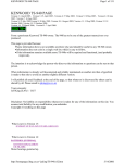
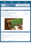
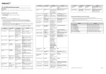
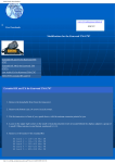
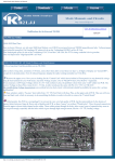
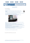
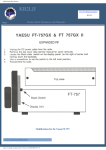
KB2LJJ Radio Mods Database and Manuals
TS 940 Mods
www.r6-ru4montesecchieta.it
IZ5CCV
Expanded xmit for Kenwood TS-940S
1. From CT1APV
2.
3. Unplug all external radio connections.
Remove top and bottom covers.
4. Remove 4 screws holding the faceplate to the chassis on the right and left side of the faceplate. Gently pull the face away from
the chassis about an inch for working room, but don't unplug anything.
5. With unit sitting upright, locate Digital Unit B. It is on the right front corner right behind the faceplate. If you have a voice
synthesizer unit the voice unit is mounted to the top of it. If not, there are 4 raised mounting holes on top to hold the voice
synthesizer unit. Remove the 4 screws from the VS-1 board, and fold it out of your way to the left.
6. Remove the 5 screws (3 on left, 2 on right) from the Digital Unit B shielding.
7. There is no need to disconnect any connectors. Tip the Digital Unit B shielding case up from the right side. Use something to
hold it up for you.
8. Now simply look on the lower right hand corner of the board. Locate IC-109. Now look up and to the left and you will find D130. Snip one lead of D-130.
9. That's it. To test, attach a dummy load and transmit out of band. Now Go back through the steps and put the unit back
together.
*******Original text below*********
Locate IC number 109.
Now find diode 130 and cut it for all-band transmit.
If you want just MARS coverage, locate IC 111 and 112, and snip diode 135 beside it.
A Brazilian ham found two factory assembly errors that, if corrected,
may improve sensitivity and AGC performance of your TS-940S.
Some corrections that may significantly AGC improving functions on the already
very famous TS-940S receiving performance
http://www.kb2ljj.com/data/kenwood/ts-940.htm (1 di 11)30/08/2009 19.53.08
KB2LJJ Radio Mods Database and Manuals
TS-940S AGC circuit improvements
The following changes will improve the adjacent rejection of the TS-940S when a relatively strong nearby signal is present (s-4 or above).
The AGC switch should remain in the SLOW position for all but high speed data communications. Most CW operations will also benefit from
operation in the SLOW position.
Parts required:
15 Kohm ¼ watt resistor, (RD14CB2E153J)
1 µF 16V Electrolytic, (CE04W1C010M)
1S1555 diode, (V1S1555)
.047 µF capacitor, (C91-0119-05)
Procedure:
RF unit
1. Remove jumper wire JP7 and replace it with the parallel combination of the 15 Kohm resistor and the 1S1555 diode. Pay close
attention to polarity.
2. Add the 1 µF capacitor as shown in the diagram.
IF unit
Change capacitor C75 from a 1 µF 50V capacitor to a .047 µF 50V capacitor.
http://www.kb2ljj.com/data/kenwood/ts-940.htm (2 di 11)30/08/2009 19.53.08
KB2LJJ Radio Mods Database and Manuals
TS-940S Factory Assembly Mistakes
Some corrections that may significantly improve the already very famous TS-940S receiving performance
Dedicated to the Detail Lists
Are you a TS-940S Rx lover? You should know that it can be even better if you do some corrections. Two errors that I found, both also
showed in the Service Manual, Revised Edition.
See the FETs Q10 (RF Preamp Preamp 2SK125, N-FET, 25V, 0.1A, 0.3W) and
Q4 Q5 (2nd balanced mixer, also 2SK125).
The picture above was scanned from the TS-940S Service Manual, Revised Edition.
In these pictures the FETs are in the wrong position.
I can assume that thousands of other TS-940S are also waiting to be corrected and perform Rx even better (mistakes "hidden" for almost
20 years!)
Check yourself with instruments, it can be probably more than 10 dB of gain and a better AGC performance.
See the Level Diagram in the Service Manual. With the FETs on the right position,
we would have 12.5 dB (17 - 4.5) gain in the RF Preamp,
and 17 dB (44 - 27) in the 2nd balanced mixer at the indicated points in the picture above.
It would be interesting to measure these gains before the correction.
With this measurement we would have an idea about the sensitivity losses due to the two errors.
I laught a lot when I confirmed both errors! Almost two decades waiting to be corrected!
As I never heard about this problem, I decided to reveal it to the whole world.
My radio was working apparently well. This is the 1st TS-940S that I could observe and analyze in detail its circuits. First I found the RF
http://www.kb2ljj.com/data/kenwood/ts-940.htm (3 di 11)30/08/2009 19.53.08
KB2LJJ Radio Mods Database and Manuals
Preamp FET in a odd position, but only few days after I could focus and see that the cascode circuit was correct in the schematic diagram
and wrong in the PC board. It was also wrong in the PC board view pictures in the Service Manual.
I also noticed that a FET was hotter than the other. It was as simple as disordered and turn the FET 180° and resolder it all over again.
Some FETs can be used either way around without any noticeable change in behaviour. However, most FETs are built with a channel
wider at one end that the other. So, although you can use a FET with the drain and source leads swapped around, most of them don't work
very well if you try it. Therefore try to correct your TS-940S. Who knows that the 2SK125 can be swapped?
This picture shows the FET in the correct position.
The RF gain increased and the noise decreased. Very fine! But, in the middle of the night, excited with this amazing discovery, I kept on
thinking if this error was the only one.
I got back to the Service Manual, and following the circuit diagram, checking the PC boards, I found a second mistake: in the 2nd
balanced mixer, in the IF unit, another inverted FET (Q4), harming the mixing/conversion, the gain, and the AGC performance.
This picture shows the FET in the correct position.
By eliminating these "losses", my famous TS-940S "won" 10 dB more! Because of that, I had to made S-Meter adjustments.
I suggest you to revise the famous TS-940S receiving performance to be even better, of course!
Our next step will be identify different N-FET for replacement. The 2SK125 is discontinued since 1996. Probably by using modern FETs,
the receiving performance will increase. Who knows?
http://www.kb2ljj.com/data/kenwood/ts-940.htm (4 di 11)30/08/2009 19.53.08
KB2LJJ Radio Mods Database and Manuals
I recommend voltage measurements before and after the correction.
The modifications were verified and tested by myself, so if you try this mod on your own equipment, it's on your own risk.
Have fun, revise your TS-940S! Smile!
Nelson Ricardo - PY1NR
Do not hesitated to contact us if you have questions
This article can also be found at http://www.guisard.com/Index_Choose_Language.htm.
TS-940S remote relay elimination
After many years of service the relay RL2 that activates the PTT to a linear amplifier can become unserviceable and its replacement is an
elaborate process involving the complete removal of the Control PCB.
All this can be avoided by substituting the relay with a transistor that can be mounted physically on the Remote Socket and only one
resistor leg needs to be cut on the Control PCB:
For use with a TL922 amplifier it is necessary to use a high-voltage transistor such as the MJE340 and a zener diode of 150V as it has a
100V DC relay coil that must be grounded for TX operation. This modification will work on any amplifier requiring pull-down for TX. If
the pull-down is only for 12V, the zener diode voltage can be lowered to 15V or eliminated all together if there is no relay.
COLLECTOR SWITCHING WAVEFORM
TS-940 PA drivers replacement
http://www.kb2ljj.com/data/kenwood/ts-940.htm (5 di 11)30/08/2009 19.53.08
KB2LJJ Radio Mods Database and Manuals
Any owner of TS-940 knows that this radio has very pour PA drivers, MRF485 from Motorola. In case of damage, to replace these
transistors you have to follow some tricky steps. To use low gain transistors, or to use high gain transistors (different dot colors) and
modify the bias, etc.
In any situation you have big chances to blow up again the drivers. The first reason is because this transistors are high voltage transistors
(29V) We know that high voltage RF transistors has higher gain then 12V transistors, and the possibility of oscillations it is also bigger. In
the same time the design of the PA layout is not one of the best, which help to oscillate.
What I did, I replaced MRF485 with 2SC2509 (or any equivalent 10 to 15W, 12V RF transistors in TO220 package). This transistor is
cheap (used in most of CB radios). Be careful to connections, 2SC2509 has different pin configuration, BEC, (MRF485 has BCE).
You have to lift the L7 inductor (Final Unit) from the 29V bar, and connect to the output of a 12V/1.5A regulator. This could be a
LM7812 (TO3 type). The input of 12V regulator was connected to 29V, from the same point where you disconnected the L7 inductor. I
installed LM7812 regulator on a small heat sink, outside of the PA compartment.
Now you have to adjust the bias of the drivers. Put low power in SSB mode and adjust VR2 (Final Unit) to have 0.7V on the base of
drivers. Finally if the output power is not 100W you can adjust VR2 (Control Unit), and VR3 (Control Unit) for ALC.
Good luck and I am not responsible for any mistakes you make!
TS-940S MRF-485 Driver Transistor News
Some MRF-485 transistors are being supplied by Motorola with a Green or Blue color ranking. If these transistors are installed without
modifying the driver bias circuit there is a strong possibility that they will fail within a very short time frame.
These high gain transistors cause the circuit to become unstable which can cause the circuit to break into self oscillation, and therefore selfdestruct.
Recommendations:
Use of Red, Orange, or Yellow hfe color rankings is recommend. These lower gain transistors work just fine and do not suffer from the
circuit instability problem. If you are only able to obtain the high gain transistors you will need to modify the varistor/temperature
compensation circuit on the final unit (X45-1400-00) by changing R16 from 1.2 Kohm to 2.2 Kohm.
During its production the TS-940S used two different varistor values. The original part was an STV3H(O). It was changed in midproduction to an SV-03YS. R15 was changed from an 820 ohm resistor to a 1 Kohm resistor at the same time. Therefore the
countermeasure differs depending upon the serial number of the radio.
Serial number
lot
Varistor
R15
R16
MRF485 Green or Higher rank
106xxxx or earlier
STV3H(O)
820
1.2 K
See "Caution below"
107xxxx or later
SV03YS
1K
2.2 K
Change R16 from 1.2 to 2.2 K
Caution: If using a Green or higher hfe rank one of the above countermeasure must be taken depending upon the serial number of the set.
After replacing the drivers check the bias current. We recommend transmitting for 1 hour in SBB mode with no modulation into a dummy
load. After this time frame check the bias current. It must not exceed 300 mA on the original radio. If the current changes you must
change R16 from 1.2 Kohm to 2.2 Kohm.
http://www.kb2ljj.com/data/kenwood/ts-940.htm (6 di 11)30/08/2009 19.53.08
KB2LJJ Radio Mods Database and Manuals
TS-940S VCO carrier to noise ratio improvement
The Carrier to Noise ratio of the TS-940S may be improved by the following changes. This bulletin supersedes bulletin number 911 dated
September 15, 1986.
Parts required:
PLL UNIT (X50-2020-00)
R120, 129
R121, 124
C180, 181
C184, 185
3.3 Kohm 1/6 watt carbon resistor RD14CB2C332J
680 ohm 1/6 watt carbon resistor RD14CB2C681J
.01 µF disc ceramic capacitor
C91-0117-05
.33 µF 35V Tantalum capacitor
CS15E1VR33M
RF UNIT (X44-1660-00)
R154, 155
C193, 194
3.9 Kohm 1/6 watt carbon resistor RD14CB2C392J
1 µF 25V Tantalum capacitor
CS15E1E010M
Procedure:
On the PLL unit (X50-2020-00) remove capacitor C176, C180, and C181. Change resistor R120 and R129 from 470 ohms to 3.3 Kohm.
Change resistor R121 and R124 from 1 Kohm to 680 ohms. Change capacitors C184 and C185 from .22 µF to .33 µF 35V tantalum
capacitors. Install C180 and C181 in the positions shown in the accompanying diagrams. The use of new capacitors is recommended to
improve reliability, don't try to reuse the old capacitors! Capacitors C181 and C180 should be attached to the foil side of the PLL unit.
On the RF unit (X44-1660-00) install the series RC circuit composed of R154 and C193, and R155 and C194, as shown in the
accompanying diagrams. As the diagrams illustrate it is easiest to move C132 and C193 to the foil side of the board and install the series
RC circuit on the component side.
This is an optional change and may not be performed under warranty. Time required for this modification is 1.5 hour or less.
http://www.kb2ljj.com/data/kenwood/ts-940.htm (7 di 11)30/08/2009 19.53.08
KB2LJJ Radio Mods Database and Manuals
PLL UNIT
RF UNIT
http://www.kb2ljj.com/data/kenwood/ts-940.htm (8 di 11)30/08/2009 19.53.08
KB2LJJ Radio Mods Database and Manuals
TS-940S PLL unlock
Some users of the TS-940S have reported a blanking of the display accompanied by a loss of transmit and receive. Readjustment of the
PLL unit will correct this tendency.
Procedure:
1. Set the Dial frequency for approximately 1.8 MHz (inside the band).
2. Using an RF probe at TP5 adjust L22, L23, and L24 for a maximum reading on the meter. You should see approximately 250 mV.
3. Adjustment of L24 will produce the greatest change, which may be up to a 90° adjustment from its present position.
TS-940S PLL unlock
Service Bulletin no. 908 (8-4-1986)
Reports of a PLL unlock on the lower frequencies may be due to low VCO levels. The following change will increase the VCO level and
should prevent reoccurrence of this symptom.
Parts required
C168, change to 15 pF 50V (CC45SLIH150J)
Procedure:
1. On the RF unit (X44-1660-00) change C168 from a 33 pF capacitor to a 15 pF 50V capacitor.
2. Readjust the VCO BPF (RF unit L74-76) according to the instructions contained in the TS-940 Service manual.
http://www.kb2ljj.com/data/kenwood/ts-940.htm (9 di 11)30/08/2009 19.53.08
KB2LJJ Radio Mods Database and Manuals
This change is applicable to units prior to serial number 606xxxx.
ALC time constant
1. This Mod will change the TS-940 time constant from approximately 1 second to .022 second. This means that the ALC will no
longer impose its own characteristics on your audio response; the ALC will now follow your own sylabbic rate and emphasis.
Usually the average output will increase, which will drive a linear amplifier harder (or at least those meters will swing higher!!).
Use caution in this mod and have another Ham-friend check around your TX frequency for splattering while you are QRV.
2. The TS-940 has a 10uF cap (C31) and 100K resistor (R104) which make up the time constant for the ALC. This tends to reduce
the output power for the duration of the ALC time constant (or till the circuit charges up again). Then it starts all over again on the
next word.
3. This procedure allows modification to the control PCB (X53-1420-11) in the TS-940 WITHOUT having to remove the board.
Remove the bottom cover and locate the control PCB. Locate R137 and R104. These are located in the upper right hand corner as
the rig faces you upside down (near VR-3). A service manual is helpfull for locating parts!!!
Using an Exacto knife, VERY CARFULLY scrape off some insulation from the top of these two resistors. Now tack-solder a 1/8
watt 2.2k ohm resistor from the top of one of these resistors to the top of the other. The time constant is now changed. Reassemble
and enjoy a superb rig.
TS-940S AVR unit capacitor change
In those areas of the country that are subject to large power line voltage fluctuations, excessive voltage may be applied to capacitor C12
on the AVR unit (X43-1500-00). These voltage fluctuations might exceed the capacitor breakdown voltage. Replacing capacitor C12 with
a capacitor having a higher breakdown voltage will help prevent this potential problem.
Procedure:
On the AVR unit (X43-1500-00) change C12 from a 6800 µF capacitor to a 5600 µF 25 V capacitor (C90-2037-05)
http://www.kb2ljj.com/data/kenwood/ts-940.htm (10 di 11)30/08/2009 19.53.08
KB2LJJ Radio Mods Database and Manuals
This change is applicable to serial numbers prior to 701xxxx.
ATTENTION
The KB2LJJ takes no responsibility for any damage during the modification or for any wrong information made on this modification.
http://www.kb2ljj.com/data/kenwood/ts-940.htm (11 di 11)30/08/2009 19.53.08