1
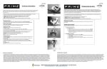
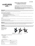
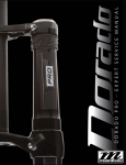
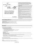
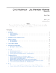
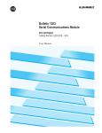
Hayes TrailTrac Kit Installation Guidelines
Models:
Rev. B
2010-2014 Polaris Rush / Pro-R / Indy
Packing List
1
1
1
1
1
1
1
1
2
2
1
6
1
1
1
15
Electronic Control Unit (ECU)
ECU Velcro, 3 inch
Switch face plate
Switch face plate adhesive
Switch
Wiring harness
Fully pre-filled and bled brake system (with Hydraulic Control Unit, HCU)
HCU mount --- black anodized aluminum, bracket
HCU mount fasteners -- bolts, lock washer and Loctite (to frame)
HCU mount fasteners -- bolts, lock washer and Loctite (to pump)
Speed sensor end cap - black anodized Al
Speed sensor end cap fasteners M8 x 1.25 nyloc nuts
Wheel speed sensor - 1 meter sensor lead
Speed sensor hold down clip for tunnel
Speed sensor hold down bolt socket head cap screw
Speed sensor routing attachments (cable ties)
Tools needed:
T25, T30, T40 Torx drivers
13 mm and 15 mm box wrench
13 mm and 15 mm deep and shallow 3/8 inch drive sockets
3/8 inch ratchet
Phillips screw driver
1/4 inch drill bit and drill
Utility knife or similar
Torque Wrench
Suitable lift that will lift the rear of the vehicle
1
Hayes TrailTrac Kit Installation Guidelines
Rev. B
Parts Overview:
Speed Sensor Install:
1. Begin with a clean work space, and all necessary tool listed above.
2. Remove front plastics from vehicle including side panels and hood.
3. Follow recommended service procedure to remove belt and driven clutch
assembly.
4. Lift the rear of the vehicle unloading the track and rear suspension.
5. Loosen track tension bolts approximately 1 inch to allow the track to hang freely.
6. Remove stock speedometer housing #5 below. Discard used nyloc nuts.
7. Remove speedometer sensor hold down bolt from cover, install sensor, and bolt to
new speedometer housing included in kit. Torque to (30 in-lbs).
8. Install new TrailTrac speed sensor and included bolt. Torque to (30 in-lbs).
9. Slide new speedometer housing on tunnel bolts, see orientation in photo above,
take care to align driveshaft bearing in housing correctly and not damage sensors.
Loosely install new supplied nuts with sensor wire hold down clips positioned
correctly. Note: As per service manual, no grease zirc is required.
10. Verify #4 gasket is not torn or damaged. Slide bearing retaining collar and align
with proper hole in the speedometer housing. Loosely install new supplied nuts.
11. Torque speedometer housing and driveshaft nut to service manual specifications.
12. Adjust track tension, and torque all fasteners to service manual specifications.
2
Hayes TrailTrac Kit Installation Guidelines
Rev. B
13. Use supplied cable ties to attach TrailTrac speed sensor wire to existing
speedometer speed sensor wire. Route new cable the same as existing. Take note
to avoid sharp edges or anything that may damage sensor wire. See photo above.
14. Reinstall driven clutch and belt according to service manual specifications.
Brake System Install:
1. With body work removed follow service manual instructions to remove stock
brake system and set aside.
2. Install brake caliper first, torque to service manual specifications.
3. Run brake line behind pull start rope, and install hydraulic unit to frame rails with
new bolts supplied with TrailTrac kit. Torque to service manual specifications.
Small 8 mm bracket bolts should be torqued to (30 in-lbs).
4. Route line in factory location along steering stem wiring harness. Note: Factory
location of hose is under frame strut.
5. Reinstall new master cylinder in stock location, reuse stock T25 Torx in the
proper locations, and torque to service manual specifications.
6. Route brake light switch to factory connector and attach line and wiring with
included cable ties. Reinstall connector protector in factory location.
7. Before riding pump brake lever 5 times to seat pads to the rotor.
Switch Install:
1.
2.
3.
4.
5.
Use switch bezel plate for a template to trace hole needed for switch install.
Place bezel in desired location to the left of the factory cluster.
Use a paint marker to trace rectangle hole.
Used a ¼ inch drill bit to drill all 4 corners of the traced rectangle.
With a new sharp utility knife connect all four holes and trim any excess plastic
inside of the traced rectangle.
6. Test fit switch first without bezel to make sure the hole is the correct size.
3
Hayes TrailTrac Kit Installation Guidelines
Rev. B
7. Once the correct size hole is made make the final install of switch and bezel
assembly. Double sided tape is included with the kit and to be used if the switch
hole is made too large in the plastic and the switch tabs do not hold properly.
Wiring Harness Install:
1. Disconnect battery positive and negative terminals.
2. Remove fuse from wiring harness and reinstall when procedure is complete.
3. Install TrailTrac ECU with supplied 3M Dual Lock adhesive in front of fuel tank.
Some models may require slightly different location due to small fuel tank
changes. See photo below.
4. Connect wiring harness to ECU first and run each harness leg to its designated
location.
5. First run battery positive and negative wires to the battery using supplied cable
ties to run harness along stock electric start harness and frame rail. See photo
below.
4
Hayes TrailTrac Kit Installation Guidelines
Rev. B
6. Disconnect stock electric start harness; install TrailTrac jumper harness between
stock connectors. See photo above to install correctly and secure with cable tires
to frame rail.
7. Connect TrailTrac speed sensor to harness plug
8. Connect TrailTrac harness to the hydraulic unit on frame rail. Use supplied cable
ties to attach harness to brake line and keep clear of steering linkage. When
secured, steer handle bars from side to side to verify no obstructions.
9. Use cable ties to attach hood harness connector to stock hood harness plug for
easy hood removal in the future. Diagnostic plug can be secured in the same
location.
10. Once completed reinstall fuse and function check system. Power vehicle on, “on”
and “off” lights should illuminate when system switch is cycled and malfunction
indicator lamp should do a self-check illumination for one second when vehicle is
powered up.
For Technical Support, please contact:
262-242-4300
HB Performance Systems Inc.
5800 West Donges Bay Road
Mequon, WI 53092
www.hayestrailtrac.com
5
Hayes TrailTrac Kit Installation Guidelines
Rev. B
Wiring Harness Diagram:
6