1
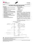
Bulletin 1203
Serial Communications Module
PPG OPTOMUX
Catalog Number 1203-GD9, –GK9
User Manual
Important User Information
Because of the variety of uses for this equipment and because of the
differences between this solid-state equipment and electromechanical
equipment, the user of and those responsible for applying this equipment
must satisfy themselves as to the acceptability of each application and use
of the equipment. In no event will Allen-Bradley Company be responsible
or liable for indirect or consequential damages resulting from the use or
application of this equipment.
The illustrations shown in this manual are intended solely to illustrate the
text of this manual. Because of the many variables and requirements
associated with any particular installation, the Allen-Bradley Company
cannot assume responsibility or liability for actual use based upon the
illustrative uses and applications.
No patent liability is assumed by Allen-Bradley Company with respect to
use of information, circuits or equipment described in this text.
Reproduction of the content of this manual, in whole or in part, without
written permission of the Allen-Bradley Company is prohibited.
This information in this manual is organized in numbered chapters. Read
each chapter in sequence and perform procedures when you are instructed
to do so. Do not proceed to the next chapter until you have completed all
procedures.
ATTENTION: Identifies information about practices or
circumstances that can lead to personal injury or death, property
damage or economic loss.
Attentions help you:
• identify a hazard
• avoid the hazard
• recognize the consequences
IMPORTANT: Identifies information that is especially important for
successful application and understanding of the product.
Summary of Changes
Summary Information
Information for the –GK9 module was added to this manual.
Summary of Changes
This Page Intentionally Left Blank
Table of Contents
Introduction
Chapter 1
Manual Objectives . . . . . . . . . . . . . . . . . . . . . . . . . . . . . . . . . . . . . . . .
Who Should Use This Manual . . . . . . . . . . . . . . . . . . . . . . . . . . . . . . .
Vocabulary . . . . . . . . . . . . . . . . . . . . . . . . . . . . . . . . . . . . . . . . . . . . . .
Firmware Support . . . . . . . . . . . . . . . . . . . . . . . . . . . . . . . . . . . . . . . .
Manual Organization . . . . . . . . . . . . . . . . . . . . . . . . . . . . . . . . . . . . . .
Safety Precautions . . . . . . . . . . . . . . . . . . . . . . . . . . . . . . . . . . . . . . . .
Product Description
Chapter 2
Chapter Objectives . . . . . . . . . . . . . . . . . . . . . . . . . . . . . . . . . . . . . . . .
Module Description . . . . . . . . . . . . . . . . . . . . . . . . . . . . . . . . . . . . . . .
SCANport Device Compatibility . . . . . . . . . . . . . . . . . . . . . . . . . . . . .
Configuration Switches . . . . . . . . . . . . . . . . . . . . . . . . . . . . . . . . . . . .
Installation
1-1
1-1
1-1
1-1
1-2
1-2
2-1
2-1
2-1
2-3
Chapter 3
Chapter Objectives . . . . . . . . . . . . . . . . . . . . . . . . . . . . . . . . . . . . . . . . 3-1
Setting Module Configuration Switches . . . . . . . . . . . . . . . . . . . . . . . 3-1
Factory Switch Settings . . . . . . . . . . . . . . . . . . . . . . . . . . . . . . . .
3-2
Switch SW1 . . . . . . . . . . . . . . . . . . . . . . . . . . . . . . . . . . . . . . . . .
3-3
Switch SW2 . . . . . . . . . . . . . . . . . . . . . . . . . . . . . . . . . . . . . . . . .
3-5
Switch SW3 . . . . . . . . . . . . . . . . . . . . . . . . . . . . . . . . . . . . . . . . .
3-6
Enclosed Style Communications Module Dimensions . . . . . . . . . . . . 3-7
Cable Connections . . . . . . . . . . . . . . . . . . . . . . . . . . . . . . . . . . . . . . . . 3-8
RS485/RS422/RS232 Connection Examples . . . . . . . . . . . . . . .
3-8
SCANport Link Connection . . . . . . . . . . . . . . . . . . . . . . . . . . . . . . . . 3-9
Cable Requirements . . . . . . . . . . . . . . . . . . . . . . . . . . . . . . . . . . .
3-9
Power Supply Connections . . . . . . . . . . . . . . . . . . . . . . . . . . . . . . . . . 3-10
Troubleshooting
Chapter 4
Chapter Objectives . . . . . . . . . . . . . . . . . . . . . . . . . . . . . . . . . . . . . . . .
Specifications
Chapter 5
Chapter Objectives . . . . . . . . . . . . . . . . . . . . . . . . . . . . . . . . . . . . . . . .
Product Specifications . . . . . . . . . . . . . . . . . . . . . . . . . . . . . . . . . . . . .
Module Compatibility . . . . . . . . . . . . . . . . . . . . . . . . . . . . . . . . . . . . .
Index
4-1
5-1
5-1
5-1
. . . . . . . . . . . . . . . . . . . . . . . . . . . . . . . . . . . . . . . . . . . . . . . . . . . . . . . . I-1
i
Table of Contents
This Page Intentionally Left Blank.
ii
Chapter
1
Introduction
Manual Objectives
The purpose of this manual is to provide you with the necessary
information to apply the Serial Communications Module which is available
for products that include the SCANportt communications port. Described
in this manual are methods for installing, configuring, and troubleshooting
the Serial Communications Module.
For information on specific features of Allen-Bradley products mentioned
herein, refer to the product user manual.
Important: Read this manual in its entirety before installing, operating,
servicing, or initializing the Serial Communications Module.
Who Should Use This Manual
This manual is intended for qualified service personnel responsible for
setting up and servicing of these devices. You must have previous
experience with and a basic understanding of communications terminology,
configuration procedures, required equipment, and safety precautions.
To make efficient use of this communications module, you must be able to
program and operate serial communications devices, as well as have a
basic understanding of the parameter settings and functions of the device to
which you are communicating.
Vocabulary
In this manual we refer to the:
S Serial Communications Module as communications module
S Variable Frequency AC Drive (Bulletin 1336 PLUS) as the drive or
SCANport device
S Earth Ground as GND
Firmware Support
This manual supports communications module firmware versions 1.xx (the
“xx” designator may vary). Features that work with specific firmware
versions will be denoted as such.
1-1
Chapter 1
Introduction
Manual Organization
This manual is divided into the following chapters.
Chapter
Title
Topics Covered
1
Introduction
Manual objectives, audience, vocabulary, firmware
support information, manual organization, safety
precautions, and serial device compatibility
2
Product Description
3
Installation
Communications Module features, configuration, and
diagnostics
Mounting, power connections, switch configuration,
cabling, and hardware
4
Troubleshooting
LED indications and fault descriptions
5
Specifications
Environmental, electrical, and communications
specifications
Safety Precautions
ATTENTION: Only personnel familiar with SCANport devices
and associated machinery should plan or implement the
installation, start-up, configuration, and subsequent maintenance of
the serial communications module. Failure to comply may result in
personal injury and/or equipment damage.
ATTENTION: This module contains ESD (Electrostatic
Discharge) sensitive parts and assemblies. Static control
precautions are required when installing, testing, servicing, or
repairing this assembly. Component damage may result if ESD
control procedures are not followed. If you are not familiar with
static control procedures, reference Allen-Bradley Publication
8000–4.5.2, Guarding Against Electrostatic Damage, or any other
applicable ESD protection handbook.
1-2
Chapter
2
Product Description
Chapter Objectives
In this chapter, you will read about:
Communications module features
Location of configuration switches
Module Description
This module is designed to be used with the 1336-EN20. It is not
compatible with any other SCANport devices. The serial device
configurations are as follows:
Designation
Enclosure
Power Supply Source
Enclosed
Enclosed
IP30
IP30
115/230V ac separately supplied
24V dc separately supplied
SCANport Device Compatibility
Used With:
1336-EN20
1336-EN20
The SCANport Serial Communications Module is compatible with the
following Allen-Bradley devices:
Device
Firmware Revision
1336-EN20
All
2-1
Chapter 2
Product Description
Figure 2.1
Enclosed Style Serial-to-SCANport Communications Module
SCANport
Connector
Serial Channel
D-Shell Connector
Power
Connection
Diagnostic
LEDS
Switch SW3
– Stop Bits
O
RX
SCANport Status
Serial Status
TX
AB0490A
Switch SW2
– Baud Rate Selection
– Parity Setting
Switch SW1
– Speed Limit
– Communications Module Address
– Communications Mode Selection
8 SW3 1
8 SW2 1
I
O
I
BOTTOM VIEW
2-2
8 SW1 1
AB0491A
Chapter 2
Product Description
Configuration Switches
The Serial Communications Module has three DIP Switches: SW1, SW2,
and SW3 (Figure 2.1). Switches are set ON or OFF as shown in Figure 2.2.
For a detailed explanation of switch configuration, refer to Chapter 3,
Installation.
Figure 2.2
Configuration Switches
Rocker Switch
Side View of Typical
Switches
Open
Side Switch
Open
Open (Off)
Open
Switch Designation as
shown in this manual
Close (On)
Off
Open
On
AB0397A
2-3
Chapter 2
Product Description
This Page Intentionally Left Blank.
2-4
Chapter
3
Installation
Chapter Objectives
In this chapter you will learn how to:
Mount the communications module
Configure the communications module
Connect power
Connect SCANport and serial communications cables
Read this chapter completely before you attempt to install or configure
your communications module. Double check all connections and option
selections before you apply power.
Important: Switch selections take effect only on power-up. If you change
selections after power is applied, cycle the power to use the new settings.
Setting Module
Configuration Switches
This publication describes switches as being either on or off. If the switch
assembly has the word OPEN printed on it, the word OPEN corresponds to
OFF (0).
In all cases, each serial device must have a unique address the target
processor can recognize.
ATTENTION: When you change the switch settings, use a blunt,
pointed instrument such as a ball point pen. Do not use a pencil
because the lead (graphite) of the pencil may damage the switch
assembly.
ATTENTION: Failure to check connections and switch settings
for compatibility with your application when configuring the
communications module could result in personal injury and/or
equipment damage due to unintended or undesirable operation.
ATTENTION: When you configure the system for the first time,
disconnect the motor from the machine or process during initial
testing.
3-1
Chapter 3
Installation
Factory Switch Settings
3-2
Switch
Setting
Communication Mode
SW1-8
Off
SW1-7
Off
SW1-6
Off
SW1-5
Off
SW1-4
Off
SW1-3
Off
SW1-2
Off
SW1-1
On
SW2-8
Off
Speed Limit Check
SW2-7
Off
Not Used
SW2-6
On
Protocol Selection
SW2-5
On
Parity Enabled
SW2-4
On
Odd Parity (if enabled)
SW2-3
On
SW2-2
On
SW2-1
On
SW3-8
Off
SW3-7
Off
SW3-6
Off
SW3-5
Off
SW3-4
Off
SW3-3
Off
SW3-2
Off
SW3-1
Off
Drive Number = 1
RS
RS422
19.2k Baudd
S p Bitss
Stop
Not Used
s d
Chapter 3
Installation
Switch SW1
Switch SW1 selects:
Communications mode selection (RS232/RS422/RS485)
Communications module address
SW1
O
F
F
O
N
8
7
6
5
4
Communications
Module Address
3
2
1
Communications
Mode Selection
AB0398B
Table 3.A
Switch SW1 Communications Mode Selection
Switch
Value
(Decimal)
SW1-2
0
1
2
SW1-1
Communications Mode
Off
Off
RS232
Off
On
RS422
On
Off
RS485
3-3
Chapter 3
Installation
Table 3.B
Switch SW1 Communications Module Address Selection
ÁÁÁÁ
ÁÁÁÁ
ÁÁÁÁ
ÁÁÁÁ
ÁÁÁÁ
ÁÁÁÁ
ÁÁÁÁ
ÁÁÁÁ
ÁÁÁÁ
ÁÁÁÁ
ÁÁÁÁ
ÁÁÁÁ
ÁÁÁÁ
ÁÁÁÁ
ÁÁÁÁ
ÁÁÁÁ
ÁÁÁÁ
ÁÁÁÁ
ÁÁÁÁ
ÁÁÁÁ
ÁÁÁÁ
ÁÁÁÁ
ÁÁÁÁ
ÁÁÁÁ
ÁÁÁÁ
ÁÁÁÁ
ÁÁÁÁ
ÁÁÁÁ
ÁÁÁÁ
ÁÁÁÁ
ÁÁÁÁ
ÁÁÁÁ
ÁÁÁÁ
ÁÁÁÁ
ÁÁÁÁ
ÁÁÁÁ
ÁÁÁÁ
ÁÁÁÁ
ÁÁÁÁ
ÁÁÁÁ
ÁÁÁÁ
ÁÁÁÁ
ÁÁÁÁ
ÁÁÁÁ
ÁÁÁÁ
ÁÁÁÁ
ÁÁÁÁ
ÁÁÁÁ
ÁÁÁÁ
ÁÁÁÁ
ÁÁÁÁ
ÁÁÁÁ
ÁÁÁÁ
ÁÁÁÁ
ÁÁÁÁ
ÁÁÁÁ
ÁÁÁÁ
ÁÁÁÁ
ÁÁÁÁ
ÁÁÁÁ
ÁÁÁÁ
ÁÁÁÁ
ÁÁÁÁ
ÁÁÁÁ
ÁÁÁÁ
ÁÁÁÁ
ÁÁÁÁ
ÁÁÁÁ
ÁÁÁÁ
ÁÁÁÁ
ÁÁÁÁ
ÁÁÁÁ
ÁÁÁÁ
ÁÁÁÁ
ÁÁÁÁ
ÁÁÁÁ
ÁÁÁÁ
ÁÁÁÁ
ÁÁÁÁ
ÁÁÁÁ
ÁÁÁÁ
ÁÁÁÁ
ÁÁÁÁ
ÁÁÁÁ
ÁÁÁÁ
ÁÁÁÁ
ÁÁÁÁ
ÁÁÁÁ
ÁÁÁÁ
ÁÁÁÁ
ÁÁÁÁ
ÁÁÁÁ
ÁÁÁÁ
ÁÁÁÁ
ÁÁÁÁ
ÁÁÁÁ
ÁÁÁÁ
ÁÁÁÁ
ÁÁÁÁ
1
Module
Address
(Decimal)
0
Module
Address
(Octal)
0
2
1
1
3
2
4
3
5
PCC Drive
No.
3-4
SW1-8
SW1-7
SW1-6
SW1-5
SW1-4
SW1-3
Off
Off
Off
Off
Off
Off
Off
Off
Off
Off
Off
On
2
Off
Off
Off
Off
On
Off
3
Off
Off
Off
Off
On
On
4
4
Off
Off
Off
On
Off
Off
6
5
5
Off
Off
Off
On
Off
On
7
6
6
Off
Off
Off
On
On
Off
8
7
7
Off
Off
Off
On
On
On
Chapter 3
Installation
Switch SW2
Switch SW2 selects the baud rate, parity, and speed limit.
SW2
O
F
F
O
N
8
7
6
5
4
Parity
Setting
3
2
1
Baud Rate
Selection
Protocol Selection
Not Used
Speed Limit
AB0492B
Table 3.C
ÁÁÁÁÁÁÁÁ
ÁÁÁÁÁÁÁÁÁÁÁÁÁÁÁÁ
ÁÁÁÁÁÁÁÁ
ÁÁÁÁÁÁÁÁÁÁÁÁÁÁÁÁ
ÁÁÁÁÁÁÁÁ
ÁÁÁÁÁÁÁÁÁÁÁÁÁÁÁÁ
ÁÁÁÁÁÁÁÁ
ÁÁÁÁÁÁÁÁÁÁÁÁÁÁÁÁ
ÁÁÁÁÁÁÁÁ
ÁÁÁÁÁÁÁÁÁÁÁÁÁÁÁÁ
ÁÁÁÁÁÁÁÁ
ÁÁÁÁÁÁÁÁÁÁÁÁÁÁÁÁ
ÁÁÁÁÁÁÁÁ
ÁÁÁÁÁÁÁÁÁÁÁÁÁÁÁÁ
ÁÁÁÁÁÁÁÁ
ÁÁÁÁÁÁÁÁÁÁÁÁÁÁÁÁ
ÁÁÁÁÁÁÁ
ÁÁÁÁÁÁÁÁ
ÁÁÁÁÁÁÁÁÁ
ÁÁÁÁÁÁÁ
ÁÁÁÁÁÁÁÁ
ÁÁÁÁÁÁÁÁÁ
ÁÁÁÁÁÁÁ
ÁÁÁÁÁÁÁÁ
ÁÁÁÁÁÁÁÁÁ
ÁÁÁÁÁÁÁÁÁÁÁÁÁÁÁ
ÁÁÁÁÁÁÁÁÁ
ÁÁÁÁÁ
ÁÁÁÁÁ
ÁÁÁÁÁ
ÁÁÁÁÁÁ
ÁÁÁÁÁÁ
ÁÁÁÁÁ
ÁÁÁÁÁ
ÁÁÁÁÁ
ÁÁÁÁÁÁ
ÁÁÁÁÁÁ
ÁÁÁÁÁ
ÁÁÁÁÁ
ÁÁÁÁÁ
ÁÁÁÁÁÁ
ÁÁÁÁÁÁ
ÁÁÁÁÁ
ÁÁÁÁÁ
ÁÁÁÁÁ
ÁÁÁÁÁÁ
ÁÁÁÁÁÁ
ÁÁÁÁÁ
ÁÁÁÁÁ
ÁÁÁÁÁ
ÁÁÁÁÁÁ
ÁÁÁÁÁÁ
ÁÁÁÁÁ
ÁÁÁÁÁ
ÁÁÁÁÁ
ÁÁÁÁÁÁ
ÁÁÁÁÁÁ
ÁÁÁÁÁ
ÁÁÁÁÁ
ÁÁÁÁÁ
ÁÁÁÁÁÁ
ÁÁÁÁÁÁ
ÁÁÁÁÁ
ÁÁÁÁÁ
ÁÁÁÁÁ
ÁÁÁÁÁÁ
ÁÁÁÁÁÁ
ÁÁÁÁÁ
ÁÁÁÁÁ
ÁÁÁÁÁ
ÁÁÁÁÁÁ
ÁÁÁÁÁÁ
Switch SW2 Speed Limit Settings
SW2-8
Function
Off
Limit Speed Command to Maximum Speed
On
Stop Drive if Command Speed is greater than Maximum Speed
Table 3.D
Switch SW2 Protocol Selection Settings
SW2-6
Function
Off
Regular OPTOMUX
On
Extended OPTOMUX
Table 3.E
Switch SW2 Parity Settings
SW2-5
SW2-4
Function
Don’t Care
Off
Parity Disabled
Off
On
Even Parity
On
On
Odd Parity
Table 3.F
Switch SW2 Baud Rate Selection
Switch Value
(Decimal)
0
SW2-3
SW2-2
SW2-1
Baud Rate
Off
Off
Off
110
1
Off
Off
On
300
2
Off
On
Off
600
3
Off
On
On
1200
4
On
Off
Off
2400
5
On
Off
On
4800
6
On
On
Off
9600
7
On
On
On
19200
3-5
Chapter 3
Installation
Switch SW3
Switch SW3 selects Stop Bits.
SW3
O
F
F
O
N
8
7
6
5
4
3
2
1
Set to Off
Stop Bits
AB0493A
Table 3.G
Switch SW3-1 – SW3-6 Settings
ÁÁÁÁÁÁ
ÁÁÁÁÁÁÁÁÁÁÁÁÁÁÁÁÁÁÁ
ÁÁÁÁÁÁ
ÁÁÁÁÁÁÁÁÁÁÁÁÁÁÁÁÁÁÁ
ÁÁÁÁÁÁ
ÁÁÁÁÁÁÁÁÁÁÁÁÁÁÁÁÁÁÁ
ÁÁÁÁÁ
ÁÁÁÁ
ÁÁÁÁÁÁÁÁÁÁÁÁÁÁÁÁ
ÁÁÁÁÁ
ÁÁÁÁ
ÁÁÁÁÁÁÁÁÁÁÁÁÁÁÁÁ
ÁÁÁÁÁ
ÁÁÁÁ
ÁÁÁÁÁÁÁÁÁÁÁÁÁÁÁÁ
ÁÁÁÁÁ
ÁÁÁÁ
ÁÁÁÁÁÁÁÁÁÁÁÁÁÁÁÁ
ÁÁÁÁÁ
ÁÁÁÁ
ÁÁÁÁÁÁÁÁÁÁÁÁÁÁÁÁ
ÁÁÁÁÁ
ÁÁÁÁ
ÁÁÁÁÁÁÁÁÁÁÁÁÁÁÁÁ
SW3-1 – SW3-6
Function
Off
Must be set to Off position
Table 3.H
Switch SW3 Stop Bit Settings
3-6
SW3-8
SW3-7
Stop Bits
Off
Off
1 Stop Bit
Off
On
1 Stop Bit
On
Off
1 Stop Bit
On
On
Illegal
Chapter 3
Installation
Enclosed Style Communications
Module Dimensions
Figure 3.1
Enclosed Style Communications Module Dimensions
44mm
(1.75)
DIN
DINRAIL
RAIL
NOTES:
1. The enclosure requires clearance at the top and bottom
for proper cooling. Additional space is required if access
to DIP switches is desired without having to remove the
device.
2. All dimensions in millimeters and (inches).
70mm
(2.7)
DIN RAIL
45mm
(1.8)
DIN Rail
Mounting Clip
TOP VIEW
BACK VIEW
45mm
(1.8)
25mm
(1)
76mm
(3.0)
123mm
(4.8)
DIN
RAIL
DIN RAIL
FRONT VIEW
25mm
(1)
SIDE VIEW
AB0406A
3-7
Chapter 3
Installation
Cable Connections
RS485/RS422/RS232 Connection Examples
Figure 3.2
RS232 Mode Port Connection Diagram
Communications Module
9-Pin D-Shell
1
COM
N.C.
TX
N.C.
RX
N.C.
N.C.
N.C.
COM
2
3
4
5
6
7
8
9
AB0501A
RS422 Mode Port Connection Diagram
Communications Module
9-Pin D-Shell
1
COM
RXD
RXD
N.C.
SHIELD
N.C.
TXD
TXD
COM
2
3
4
5
6
7
8
9
AB0502A
RS485 Mode Port Connection Diagram
Communications Module
9-Pin D-Shell
1
COM
N.C.
N.C.
N.C.
SHIELD
N.C.
TXD/RXD
TXD/RXD
COM
2
3
4
5
6
7
8
9
AB0503A
3-8
Chapter 3
Installation
SCANport Link Connection
Cable Requirements
SCANport cables are available in either male–to–male or male–to–female
configuration. Cables (C) of up to 10 meters (33 feet) can be connected
from the master to the SCANport device. If a Port Expander (B1) is used,
subtract the cable length from the master to the Port Expander from the
cable length used to connect the device to the expander
(B1 + C = maximum of 10 meters).
3-9
Chapter 3
Installation
Power Supply Connections
The enclosed communications module is powered from a separate 24V dc
or 115/230V ac power supply (Figure 3.3). With the open-style
communications module board mounted in the drive, no separate power
supply connections are required.
Figure 3.3
Typical Power Supply Connection
115/230V
Typical
Connection
115V AC Hi
115V AC Low
L
N
G
GND
Enclosed
Communications Module
24V DC
Typical
Connection
+
–
G
24V DC +
Power
Supply –
GND
3-10
Enclosed
Communications Module
Chapter
Chapter
4
Troubleshooting
Chapter Objectives
Use this chapter to help troubleshoot your serial communications system
using the LED indicators on the front of the device (Figure 4.1). The
communications module is a non-serviceable device that should be
returned to Allen-Bradley for replacement when a major fault exists that is
attributable to the communications module itself.
Figure 4.1
LED Locations
Front View Enclosed Version
RX
SCANport Sts
Serial Sts
TX
AB0498A
ATTENTION: Servicing energized industrial control equipment
can be hazardous. Electrical shock, burns, or unintentional
actuation of controlled industrial equipment may cause death or
serious injury. Follow the safety-related practices of NFPA 70E,
Electrical Safety for Employee Workplaces, when working on or
near energized equipment. Do not work alone on energized
equipment.
ATTENTION: Do not attempt to defeat or override fault circuits.
The cause of a fault indication must be determined and corrected
before attempting operation. Failure to correct a drive or system
malfunction may result in personal injury and/or equipment
damage due to uncontrolled machine system operation.
4-1
Chapter 4
Troubleshooting
Table 4.A
LED Troubleshooting Table
Indicator
Serial Sts
SCANport Sts
TX
RX
4-2
Color
Description
Recommended Action
Green (Blinking)
Link OK, off-line
Check configuration switch settings,
check for serial cable connection,
cycle communications module power
Green (Steady)
Link OK, on-line
None, system functioning properly
Red (Steady)
Faulted
Check configuration switch settings,
check for serial cable connection,
cycle power, replace module
Green (Blinking)
Link OK, not connected
Check configuration switch settings,
check for serial cable connection,
cycle power
Green (Steady)
Link OK, connected
None
Red (Steady)
Faulted
Check configuration switch settings,
check for serial cable connection,
cycle power, replace module
Off
No transmission occurring
Send serial data again
Amber
Transmission occurring
None
Off
No transmission received
Check data device to verify it is sending
data
Amber
Transmission being received
None
Chapter
5
Specifications
Chapter Objectives
This chapter provides background information and specifications that you
may need when installing or applying your communications module.
Product Specifications
Enclosed Style 115/230V AC
Enclosed Style 24V DC
–GD9
–GK9
0 to 50C (32 to 122F)
0 to 50C (32 to 122F)
Storage Temperature
–40 to 85C (–40 to 185F)
–40 to 85C (–40 to 185F)
Relative Humidity
0 to 95%, Non-condensing
0 to 95%, Non-condensing
85 to 264V ac, 1-phase
24V dc ± 10%
45 to 63 Hz
NA
35mA maximum
0.4 amps maximum
60mA dc
60mA dc
SCANport Peripheral
Interface
SCANport Peripheral
Interface
Serial Side
OPTOMUX
OPTOMUX
Baud Rates
110, 300, 600, 1200, 2400,
4800, 9600, 19.2K
110, 300, 600, 1200, 2400,
4800, 9600, 19.2K
45w x 76h x 123d mm
(1.8 x 3.0 x 4.8 in.)
45w x 76h x 123d mm
(1.8 x 3.0 x 4.8 in.)
Catalog Number:
Environmental:
Operating Temperature
Electrical:
Input Voltage
Input Frequency
Input Current
SCANport Load
Communications:
SCANport Side
Dimensions:
NEMA Type 1 (IP30)
Module Compatibility
This module is intended for use with devices that communicate via RS232,
RS422, or RS485 hardware standards using OPTOMUX. It is intended to
provide a means for transmitting messages between these serialcommunications devices and Allen-Bradley SCANport devices.
5-1
Chapter 5
Specifications
This Page Intentionally Left Blank.
5-2
Index
Index
C
Cable Connections, 3-8
Cable Requirements
Cable length, 3-9
Port Expander, 3-9
SCANport, 3-9
M
Manual
Audience, 1-1
Objectives, 1-1
Organization, 1-2
Module Communication Compatibility, 5-1
Communications Module
Compatibility, 5-1
Configuration Switches, 2-3
Device Compatibility, 2-1
Enclosed Style, 2-2
Enclosed Style Dimensions, 3-7
Product Description, 2-1
Product Specifications, 5-1
Setting Configuration Switches, 3-1
Module Configurations, Factory Switch Settings, 3-2
Connection Examples
RS232, 3-8
RS422, 3-8
RS485, 3-8
Safety Precautions, 1-2
Connections
Cable, 3-8
Power Supply, 3-10
SCANport Link, 3-9
Setting Configuration Switches, 3-1
D
DIP Switches, Description, 2-3
E
Enclosed-Style Module
Dimensions, 5-1
Specifications, 5-1
F
Factory Switch Settings, Overview, 3-2
Firmware
Support, 1-1
Versions, 1-1
L
LED Indicators, and Troubleshooting, 4-1
LED Locations, 4-1
LED Troubleshooting Table, 4-2
P
Power Supply Connections, 3-10
Enclosed module, 3-10
Open-style module, 3-10
S
SCANport Link Connection, 3-9
Serial Device, Configurations, 2-1
Special Terms, 1-1
Specifications, 5-1
Switch SW1 Settings
Address Selection, 3-4
Communications Mode, 3-3
Functions, 3-3
Switch SW2 Settings
Baud Rate Selection, 3-5
Functions, 3-5
Parity Selection, 3-5
Speed Limit Settings, 3-5
Switch SW3 Settings
Functions, 3-6
Stop Bits, 3-6
T
Target processor, and unique addresses, 3-1
Troubleshooting
LED Locations, 4-1
LED Table, 4-2
Reception LED, 4-2
SCANport Sts LED, 4-2
Serial Sts LED, 4-2
Transmission LED, 4-2
I-1
Index
This Page Intentionally Left Blank.
I-2
Notes
N-1
Notes
N-2
Notes
N-3
Notes
N-4
We Want Our Manuals to be the Best!
You can help! Our manuals must meet the needs of you, the user. This is your opportunity to make sure they do just that.
By filling out this form you can help us provide the most useful, thorough, and accurate manuals available. Please take a
few minutes to tell us what you think. Then mail this form, FAX it, or send comments via E-Mail.
FAX: to your local Allen-Bradley Sales Office or 414/242-8579
E-Mail: via Internet to “[email protected]”
PUBLICATION NAME
PUBLICATION NUMBER, DATE AND PART NUMBER (IF PRESENT)
✓ CHECK THE FUNCTION THAT MOST CLEARLY DESCRIBES YOUR JOB.
SUGGEST / RESPONSIBLE FOR THE PURCHASE OF EQUIPMENT
MAINTAIN / OPERATE PROGRAMMABLE MACHINERY
DESIGN / IMPLEMENT ELECTRICAL SYSTEMS
TRAIN/EDUCATE MACHINE USERS
SUPERVISE FLOOR OPERATIONS
✓ WHAT LEVEL OF EXPERIENCE DO YOU HAVE WITH EACH OF THE FOLLOWING PRODUCTS?
NONE
LITTLE
MODERATE
EXTENSIVE
PROGRAMMABLE CONTROL
AC / DC DRIVES
PERSONAL COMPUTERS
NC / CNC CONTROLS
DATA COMMUNICATIONS / LAN
✓ RATE THE OVERALL QUALITY OF THIS MANUAL BY CIRCLING YOUR RESPONSE BELOW. (1) = POOR (5) = EXCELLENT
HELPFULNESS OF INDEX / TABLE OF CONTENTS
1
2
3
4
5
CLARITY
1
2
3
4
5
EASE OF USE
1
2
3
4
5
ACCURACY AND COMPLETENESS
1
2
3
4
5
QUALITY COMPARED TO OTHER COMPANIES’ MANUALS
1
2
3
4
5
QUALITY COMPARED TO OTHER ALLEN-BRADLEY MANUALS
1
2
3
4
5
✓ WHAT DID YOU LIKE MOST ABOUT THIS MANUAL?
✓ WHAT DID YOU LIKE LEAST ABOUT THIS MANUAL?
✓ PLEASE LIST ANY ERRORS YOU FOUND IN THIS MANUAL (REFERENCE PAGE, TABLE, OR FIGURE NUMBERS).
CUT ALONG DOTTED LINE
✁
✓ DO YOU HAVE ANY ADDITIONAL COMMENTS?
✓ COMPLETE THE FOLLOWING.
NAME
COMPANY
TITLE
DEPARTMENT
STREET
TELEPHONE
CITY
STATE
DATE
ZIP
FOLD HERE
FOLD HERE
NO POSTAGE
NECESSARY
IF MAILED
IN THE
UNITED STATES
BUSINESS REPLY MAIL
FIRST CLASS
PERMIT NO. 413
MEQUON, WI
POSTAGE WILL BE PAID BY ADDRESSEE
ALLEN-BRADLEY
Attn: Marketing Communications
P.O. Box 760
Mequon, WI 53092-9907
SCANport is a trademark of Allen-Bradley Company, Inc.
Publication 1203-5.4 — April, 1996
Supersedes July, 1995
P/N 74002-125-01(B)
Copyright 1994, Allen-Bradley Company, Inc. Printed in USA