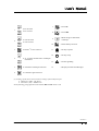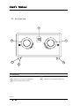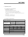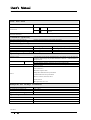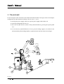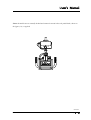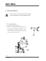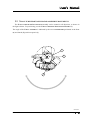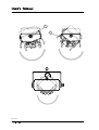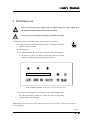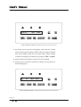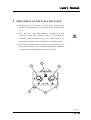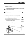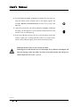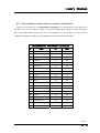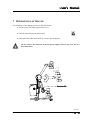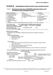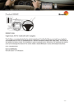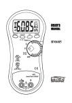
1
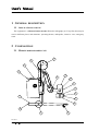
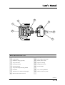
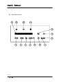
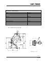
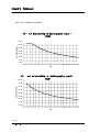
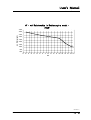
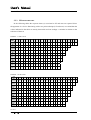
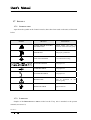
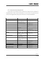
Basic 100-15 100-30 Mobile Radiographic Unit User’s Manual VIA ALDO MORO 5/7 I-24020 SCANZOROSCIATE BERGAMO ITALY +39 035 66.81.63 FAX +39 035 66.81.66 Doc. 6092 User’s Manual Index Section 0 Doc. 7747 Page 1 of 4 User’s Manual INDEX General Index Section 0 - Index (doc. 7747) Valid from 6th June 2004 Page Section 1 - General description (doc. 7748) 1 2 3 General description 2 1.1 2 Applications and use Composition 2 2.1 Mobile radiographic unit 2 2.2 Control panel 4 2.3 Collimator 6 Technical data 7 3.1 Classification of the apparatus 7 3.2 Technical characteristics 7 3.2.1 Dimensions and weigths 9 3.2.2 kV – mA Relationship 10 3.2.3 12 RX exposure time Section 2 – Safety and Maintenance (doc. 7749) 1 Safety 2 1.1 2 Introduction 1.2 Responsibility declaration 3 1.3 Compliance and reference address 3 1.4 System safety 3 1.4.1 Mechanical safety 3 1.4.2 Electrical safety 3 1.5 Protection against ionising radiation 4 1.6 Residual risks 5 Section 0 Page 2 of 4 Doc. 7747 User’s Manual INDEX Pag. 2 1.7 Signals 6 1.7.1 Symbols used 6 1.7.2 Labelling 6 1.7.3 Signalling and alarm messages 7 Maintenance 8 2.1 Routine maintenance 8 2.1.1 General racommendations 8 2.1.2 Frequent checks and inspections 9 2.2 Cleaning and disinfection 9 2.3 Disposal of device 10 Section 3 – Use of the unit (doc. 7750) 1 Transport 2 2 Unit movements 4 2.1 Arm positioning 4 2.2 X-ray tube head/collimator assembly movements 5 3 Switching on 7 4 Configuration 9 4.1 Changing the language for the unit console 9 4.2 Programming the anatomical techniques 10 5 Adjustment of the X-ray field size 11 6 Emission of X-rays 13 6.1 Emission of X-rays using the manual technique 13 6.2 X-ray emission using the anatomical technique 15 Operations after use 17 7 Section 0 Doc. 7747 Page 3 of 4 User’s Manual INDEX Annex 1 – Responsibility Declaration Annex 2 – Labelling Annex 3 – Dosimeter (optional) Section 0 Page 4 of 4 Doc. 7747 User’s Manual General Description Section 1 Doc. 7748 Page 1 of 14 User’s Manual GENERAL DESCRIPTION 1 GENERAL DESCRIPTION 1.1 APPLICATIONS AND USE The equipment is a MOBILE RADIOGRAPHIC UNIT for radiography on X-ray film, that may be used in different places and situations: operating theatre, orthopedics, intensive care, emergency room. 2 COMPOSITION 2.1 MOBILE RADIOGRAPHIC UNIT 18 3 2 1 4 15 5 6 7 9 14 8 10 19 13 11 Section 1 Page 2 of 14 Doc. 7748 User’s Manual GENERAL DESCRIPTION 2 12 4 1 16 9 8 MOBILE RADIOGRAPHIC UNIT 1 Transport handle with brake 11 Pivoting wheel (front wheel) 2 Control panel 12 Power supply cable holder 3 Handle for tilting (optional) 13 Wheels (main wheel) 4 X-ray tube head 14 Support for Tilting 5 Lateral goniometer 15 Pantograph arm lock 6 Front goniometer 16 Cassette holder 7 X-ray tube head positioning handle … 8 Collimator 18 X-ray control pushbutton 9 Adjustment of collimator diaphragms 19 Pedal for Stationary brake 10 Rail for filters and accessories Section 1 Doc. 7748 Page 3 of 14 User’s Manual GENERAL DESCRIPTION 2.2 CONTROL PANEL 14 13 12 11 10 9 8 1 2 3 4 5 6 7 Section 1 Page 4 of 14 Doc. 7748 User’s Manual GENERAL DESCRIPTION 1 2 kV kV increase mAs mAs decrease mAs increase HP/LP (1) Power selection 3 4 kV decrease Prog N° of exams memorized in Technique Anatomical 5 Anatomical Technique Selection 6 Collimator light activation 7 Unit ON 8 Unit OFF 9 Data storage in anatomical technique 10 Potter-Bucky selection 11 X-Ray exposure 12 X-Ray ready 13 Alarm signalling 14 Display for Dates and Messages (1) A change of the Power level involves a change of the used focal spot: • High Power (HP) – Big Focus • Low Power (LP) – Small Focus In the following paragraphs the abbreviations HP and LP will be used. Section 1 Doc. 7748 Page 5 of 14 User’s Manual GENERAL DESCRIPTION 2.3 COLLIMATOR 50 51 54 52 52 53 COLLIMATOR 50 Collimator light on 53 Retractile meter 51 Adjustment of transverse diaphragm 54 Adjustment of longitudinal diaphragm 52 Rail for filters and accessories Section 1 Page 6 of 14 Doc. 7748 User’s Manual GENERAL DESCRIPTION 3 TECHNICAL DATA 3.1 CLASSIFICATION OF THE APPARATUS CLASSIFICATION – EN 60601 1 § 5 ¯ Type of protection against short circuit: CLASS I ¯ Degree of protection against direct and indirect contact: TYPE B ¯ Use conditions: CONTINUOUS WORKING WITH INTERMITTENT LOAD ¯ Unit not to be used in the presence of an inflammable anaesthetic mixture with air or nitrous oxide CLASSIFICATION – 93/42/EEC DIRECTIVE ¯ In according with Annex IX: CLASS II b 3.2 TECHNICAL CHARACTERISTICS Electrical characteristics SINGLE PHASE VOLTAGE FREQUENCY 230 Vac ± 10%, 16 A (Optional: 115 Vac ± 10%) 50/60 Hz STAND-BY WORKING 1 A (115 Vac: 2.5 A) RADIOGRAPHY WORKING 12 A (115 Vac: 23 A) MAX ABSORBED CURRENT LINE COMPENSATION LINE RESISTANCE Automatic < 2.5 Ω Radiological characteristics 15 kW LP (Low Power) MAX POWER 7.5 kW MAX CURRENT IN RADIOGRAPHY 150 mA EXPOSURE TIME WORKING FREQUENCY RANGE KV RANGE MAS A.T. PILOTAGE RIPPLE TOTAL FILTRATION RISING TIME HP (High Power) 30 kW LP (Low Power) 15 kW 7.5 kW 375 mA 150 mA 3 ms ÷ 1.3 s 1 ms ÷ 0.6 s 3 ms ÷ 1.3 s Selected by the processor according to the mAs 100 kHz 40 ÷ 125 (Step of 1 kV) 0.5 ÷ 200 in 25 values Inverter driven by IGBT ≤ 3% at Max Power > 2.7 mmAl ≤ 1 ms HP (High Power) 30 kW 425 mA 1 ms ÷ 0.5 s Section 1 Doc. 7748 Page 7 of 14 User’s Manual GENERAL DESCRIPTION X-Ray Tube Head Rotation with speed 3000 RPM TYPE OF ANODE 0.6 mm FOCAL SPOTS 1.3 mm All the other information relevant to the X-Ray Tube Head and to the X-Ray Tube can be found in the X-Ray Tube Head Technical Data Sheet Collimator (optional) SHUTTERS TO MULTIPLE PLANS Parallels and perpendicular with manual movement All the other information relevant to the Collimator can be found in the relative Technical Data Sheet Dosimeter (optional) MODEL ACTIVE AREA MINIMAL DOSE RESOLUTION MAXIMAL MEASURABLE DOSE Kermax-plus 146 x 146 mm2 1 mGycm2 9999.9999 mGycm2 VacuDap 2000 with printer optional 147 x 147 mm2 1 mGycm2 9999.9999 mGycm2 Operating modes and functionality INTERFACE USER OPERATING MODES RADIOGRAPHY X-RAY CONTROL Polycarbonate flat keyboard with alphanumeric LCD display for all the operative parameters and messages of possible anomalous conditions – administrated by a microprocessor. Two-points techniques (kV-mAs) 40 programmable anatomic technique (20 for LP and 20 for HP) Distance control with double – click and extensible cable (≥4m) Filament current mAmin and mAmax Maximum exposure time Temperature maximum X-ray tube head SAFETY Count thermal units X-ray tube head Max kV, min kV, max ∆kV, max I Anode rotation Microprocessor self – test Transport and storage conditions MAXIMAL TEMPERATURE RECOMMENDED TEMPERATURE RELATIVE HUMIDITY ATMOSPHERIC PRESSURE –10°C ÷ 55°C 0°C ÷ 40°C 20% ÷ 90% 500 hPa ÷ 1060 hPa Operating conditions TEMPERATURE RELATIVE HUMIDITY ATMOSPHERIC PRESSURE 10°C ÷ 40°C 30% ÷ 75% 700 hPa ÷ 1060 hPa Section 1 Page 8 of 14 Doc. 7748 User’s Manual GENERAL DESCRIPTION Mechanical Characteristics WIDTH LENGHT HEIGHT MIN SOURCE-FLOOR DISTANCE MAX SOURCE-FLOOR DISTANCE MAX RANGE FOCUS MAXIMUM HEIGHT, WITH RANGE 1000 MM PIVOTING FRONT WHEEL Ø 75 MAXIMUM DIFFERENCE IN LEVEL WHICH CAN BE OVERCOME WITH TILTING BACK WHEELS DIAMETER MINIMUM DEFLECTING RAY WEIGHT MOVEMENT CASSETTE HOLDER 35X43 734 mm 1259 mm 1467 mm 489 mm 1997 mm 1091 mm 1656 mm 360° 25 mm Ø 200 977 mm 191 kg (115 Vac: 205 kg) Manual 4 3.2.1 DIMENSIONS AND WEIGTHS Drawing N°: 7742 Section 1 Doc. 7748 Page 9 of 14 User’s Manual GENERAL DESCRIPTION 3.2.2 KV – mA RELATIONSHIP kV - mA Relationship in Radiography mode 7.5kW 160,00 mA Radiography 140,00 120,00 100,00 80,00 60,00 40,00 20,00 35 40 45 50 55 60 65 70 75 80 85 90 95 100 105 110 115 120 125 kV kV - mA Relationship in Radiography mode 15kW 420,00 mA Radiography 370,00 320,00 270,00 220,00 170,00 120,00 70,00 20,00 35 40 45 50 55 60 65 70 75 80 85 90 95 100 105 110 115 120 125 kV Section 1 Page 10 of 14 Doc. 7748 User’s Manual GENERAL DESCRIPTION kV - mA Relationship in Radiography mode 30kW 470,00 420,00 mA Radiography 370,00 320,00 270,00 220,00 170,00 120,00 70,00 20,00 35 40 45 50 55 60 65 70 75 80 85 90 95 100 105 110 115 120 125 kV Section 1 Doc. 7748 Page 11 of 14 User’s Manual GENERAL DESCRIPTION 3.2.3 RX EXPOSURE TIME In the following tables the exposure times (s) associated to kV and mAs are reported. Since the apparatus is a device functioning with a two point technique (kV and mAs) we remind that the values indicated in the table are merely theoretical and can undergo a variation in relation to the tolerance of the mA. TABLE 1 – 7.5KW POWER mAs 0,5 1 1,3 1,6 2 2,5 3,2 4 5 6,3 8 10 13 16 20 25 32 40 50 63 80 100 130 160 200 kV 40 0,003 0,006 0,008 0,010 0,013 0,016 0,021 0,026 0,033 0,042 0,053 0,066 0,086 0,106 0,133 0,166 0,213 0,266 0,333 0,420 0,533 0,666 0,866 1,066 1,333 (150mA) 50 0,003 0,006 0,008 0,010 0,013 0,016 0,021 0,026 0,033 0,042 0,053 0,066 0,086 0,106 0,133 0,166 0,213 0,266 0,333 0,420 0,533 0,666 (150mA) 60 0,004 0,008 0,010 0,012 0,016 0,020 0,025 0,032 0,040 0,050 0,064 0,080 0,104 0,128 0,160 0,200 0,256 0,320 0,400 0,504 0,640 (125mA) 70 0,004 0,009 0,012 0,014 0,018 0,023 0,029 0,037 0,046 0,058 0,074 0,093 0,121 0,149 0,186 0,233 0,299 0,373 0,467 0,588 (107mA) 80 0,005 0,010 0,013 0,017 0,021 0,026 0,034 0,043 0,053 0,067 0,086 0,107 0,139 0,172 0,215 0,268 0,344 0,430 0,537 0,677 (93mA) 90 0,006 0,012 0,015 0,019 0,024 0,030 0,038 0,048 0,060 0,075 0,096 0,120 0,156 0,192 0,240 0,301 0,385 0,481 0,602 (83mA) 100 0,006 0,013 0,017 0,021 0,026 0,033 0,042 0,053 0,066 0,084 0,106 0,133 0,173 0,213 0,266 0,333 0,426 0,533 0,666 (75mA) 110 0,007 0,014 0,019 0,023 0,029 0,036 0,047 0,058 0,073 0,092 0,117 0,147 0,191 0,235 0,294 0,367 0,470 0,588 (68mA) 120 0,008 0,016 0,020 0,025 0,032 0,040 0,051 0,064 0,080 0,101 0,129 0,161 0,209 0,258 0,322 0,403 0,516 0,645 (62mA) 125 0,008 0,017 0,022 0,027 0,034 0,042 0,054 0,068 0,085 0,107 0,136 0,169 0,220 0,271 0,339 0,424 0,542 0,678 (59mA) TABLE 2 – 15KW POWER mAs 0,5 1 1,3 1,6 2 2,5 3,2 4 5 6,3 8 10 13 16 20 25 32 40 50 63 80 100 130 160 200 kV 40 0,001 0,002 0,003 0,004 0,005 0,006 0,008 0,010 0,013 0,016 0,021 0,026 0,034 0,042 0,053 0,066 0,085 0,106 0,133 0,168 0,213 0,266 0,346 0,426 0,533 (375mA) 50 0,001 0,003 0,004 0,005 0,006 0,008 0,010 0,013 0,016 0,021 0,026 0,033 0,043 0,053 0,066 0,083 0,106 0,133 0,166 0,210 0,266 0,333 0,433 0,533 (300mA) 60 0,002 0,004 0,005 0,006 0,008 0,010 0,012 0,016 0,020 0,025 0,032 0,040 0,052 0,064 0,080 0,100 0,128 0,160 0,200 0,252 0,320 0,400 0,520 (250mA) 70 0,002 0,004 0,006 0,007 0,009 0,011 0,014 0,018 0,023 0,029 0,037 0,046 0,060 0,074 0,093 0,116 0,149 0,186 0,233 0,294 0,373 0,467 0,607 (214mA) 80 0,002 0,005 0,006 0,008 0,010 0,013 0,017 0,021 0,026 0,033 0,042 0,053 0,069 0,085 0,106 0,133 0,171 0,213 0,267 0,336 0,427 0,534 (187mA) 90 0,003 0,006 0,007 0,009 0,012 0,015 0,019 0,024 0,030 0,037 0,048 0,060 0,078 0,096 0,120 0,150 0,192 0,240 0,301 0,379 0,481 0,602 (166mA) 100 0,003 0,006 0,008 0,010 0,013 0,016 0,021 0,026 0,033 0,042 0,053 0,066 0,086 0,106 0,133 0,166 0,213 0,266 0,333 0,420 0,533 (150mA) 110 0,003 0,007 0,009 0,011 0,014 0,018 0,023 0,029 0,036 0,046 0,058 0,073 0,095 0,117 0,147 0,183 0,235 0,294 0,367 0,463 0,588 (136mA) 120 0,004 0,008 0,010 0,012 0,016 0,020 0,025 0,032 0,040 0,050 0,064 0,080 0,104 0,128 0,160 0,200 0,256 0,320 0,400 0,504 (125mA) 125 0,004 0,008 0,011 0,013 0,016 0,021 0,026 0,033 0,041 0,052 0,066 0,082 0,107 0,132 0,165 0,207 0,264 0,331 0,413 0,521 (121mA) Section 1 Page 12 of 14 Doc. 7748 User’s Manual GENERAL DESCRIPTION TABLE 3 – 30KW POWER mAs 0,5 1 1,3 1,6 2 2,5 3,2 4 5 6,3 8 10 13 16 20 25 32 40 50 63 80 100 130 160 200 kV 40 0,001 0,002 0,003 0,003 0,004 0,005 0,007 0,009 0,011 0,014 0,018 0,023 0,030 0,037 0,047 0,058 0,075 0,094 0,117 0,148 0,188 0,235 0,305 0,376 0,470 (425mA) 50 0,001 0,002 0,003 0,004 0,005 0,006 0,008 0,010 0,012 0,015 0,020 0,025 0,032 0,040 0,050 0,062 0,080 0,100 0,125 0,157 0,200 0,250 0,325 0,400 (400mA) 60 0,001 0,002 0,003 0,004 0,005 0,006 0,008 0,010 0,013 0,016 0,021 0,026 0,034 0,042 0,053 0,066 0,085 0,106 0,133 0,168 0,213 0,266 0,346 (375mA) 70 0,001 0,002 0,003 0,004 0,005 0,007 0,009 0,011 0,014 0,017 0,022 0,028 0,036 0,045 0,056 0,070 0,090 0,112 0,140 0,177 0,225 0,281 0,366 (355mA) 80 0,001 0,002 0,003 0,004 0,005 0,007 0,009 0,011 0,014 0,018 0,023 0,029 0,038 0,047 0,059 0,074 0,094 0,118 0,148 0,186 0,237 0,296 (337mA) 90 0,001 0,003 0,004 0,005 0,006 0,007 0,010 0,012 0,015 0,019 0,025 0,031 0,040 0,050 0,062 0,078 0,100 0,125 0,156 (320mA) 100 0,001 0,003 0,004 0,005 0,006 0,008 0,010 0,013 0,016 0,021 0,026 0,033 0,043 0,053 0,066 0,083 0,106 0,133 0,166 (300mA) 110 0,002 0,004 0,006 0,007 0,009 0,012 0,015 0,019 0,024 0,030 0,039 0,049 0,063 0,078 0,098 0,122 0,156 0,196 0,245 0,308 0,392 (204mA) 120 0,003 0,007 0,009 0,011 0,014 0,017 0,022 0,028 0,035 0,044 0,056 0,070 0,092 0,113 0,141 0,177 0,226 0,283 0,354 0,446 (141mA) 125 0,004 0,008 0,010 0,013 0,016 0,020 0,026 0,032 0,040 0,050 0,063 0,079 0,103 0,127 0,159 0,198 0,254 0,317 0,397 0,500 (126mA) Section 1 Doc. 7748 Page 13 of 14 User’s Manual GENERAL DESCRIPTION Section 1 Page 14 of 14 Doc. 7748 User’s Manual Safety and Maintenance Section 2 Doc. 7749 Page 1 of 10 User’s Manual SAFETY AND MAINTENANCE 1 SAFETY 1.1 INTRODUCTION The aim of this manual is to provide qualified radiology technicians, medical and paramedical staff with operating instructions to make use of the radiographic unit simple and safe. This apparatus emits X-RAYS and must only be used in compliance with the safety instructions indicated in this manual and must not be used for any other purposes than those foreseen. The system must only be used by personnel with the necessary knowledge in the field of radiation protection and with the necessary training in use of X-ray apparatus. Follow the indications given below very carefully: the apparatus must not be used when there are any electrical and/or mechanical faults; do not use the system when any signalling or alarm device of the system is not working properly; under no circumstances work with the unit in places saturated with vapours and/or flammable gases or explosives; any modification to the system must be authorised in writing by the MANUFACTURER; if you want to use the apparatus in combination with other equipment, components or modules, and when compatibility with the latter is not certain, it is indispensable to make sure that there is no danger to the patients and/or operating personnel. In this case, consult the manufacturer of the apparatus in question or an expert in the sector; like any other apparatus, the System must be used correctly. It also need PERIODIC CHECKS AND MAINTENANCE as specified under § 2.1 in this section; all maintenance, repair and/or modification work must be carried out by PERSONNEL QUALIFIED AND AUTHORIZED by the Manufacturing Company. The latter declines any responsibility for malfunctions caused by unauthorised interventions; the MANUFACTURING COMPANY of the apparatus declines any responsibility for damage to people and/or things caused by its improper use. Section 2 Page 2 of 10 Doc. 7749 User’s Manual SAFETY AND MAINTENANCE 1.2 RESPONSIBILITY DECLARATION Encosed to the presente manual the MANUFACTURER RESPONSIBILITY DECLARATION (SEE ANNEX 1). 1.3 COMPLIANCE AND REFERENCE ADDRESS For information relevant to the compliance make always reference to ANNEX 1. 1.4 SYSTEM SAFETY 1.4.1 MECHANICAL SAFETY For moving the unit only use the proper handle for tilting operations of the unit only use the proper handles and relative tail rotor control panel avoid hitting the unit against obstacles do not remove the protective casing of the apparatus except for maintenance work expressly foreseen and described in this USER’S MANUAL or in the SERVICE MANUAL. 1.4.2 ELECTRICAL SAFETY Make sure that the power supply socket where the apparatus is to be connected is approved for the foreseen voltage and current for use of the system the radiology system must not be used in rooms where there is the risk of explosion disconnect the installation from the mains before carrying out any cleaning, disinfection and/or sterilisation the cleaning and disinfection products for the installation can form explosive gaseous mixtures. It is compulsory to only use products which comply with the corresponding Standards in force take care not to spill conductive liquids on the apparatus as they would jeopardise operation and safety were they to penetrate to the inside always turn the apparatus off after use. Section 2 Doc. 7749 Page 3 of 10 User’s Manual SAFETY AND MAINTENANCE 1.5 PROTECTION AGAINST IONISING RADIATION Before carrying out any X-ray exposure, make sure that all the necessary precautions against radiation have been taken. During radiation emission, the personnel in the X-ray room must respect the regulations in force regarding protection against radiation. For this, bear in mind the following rules: where necessary, use protective accessories against radiation; always use the special X-ray protective coats: an X-ray protective material equivalent to 0.35 mm of lead (0.35 mm Pb) attenuates the radiation produced at 50 kV by 99.95% and at 100 kV by 94.5%; the best protection against radiation is distance: therefore keep as far away as possible both from the source of radiation and from the exposure object, also by using the suited exposure-push-button with its extensible cable; avoid moving or standing in the path of the rays; always use the smallest exposure range possible: the radiation dispersed largely depends on the volume of the object X-rayed; keep the patient’s examination area the furthest away as possible from X-ray source. Section 2 Page 4 of 10 Doc. 7749 User’s Manual SAFETY AND MAINTENANCE 1.6 RESIDUAL RISKS The system is designed and constructed according to the strictest principles of compliance with safety requirements. However, there are residual risks due either to incorrect use of the apparatus or to deficiencies in the protective measures taken. With regard to the risks due to incorrect use of the apparatus, please see the instructions and recommendations given in the points above and we underline that: The mobile unit has been designed and constructed so that it will not tilt over up to an angle of 10° to horizontal in transport position (SEE SECTION 3 - § 1). It is therefore advisable: • not to stand, move or place the mobile unit on surfaces with a slope of more than 10° • not to try to move the mobile unit with the brakes on • to take care to avoid any obstacles on the floor when moving the mobile unit (cables, steps and uneven levels of all kinds) For the residual risks due to any defect in the protection measures taken, it must be remembered that: Protection against electric shocks is carried out by means connecting the metallic covering parts of the apparatus to earth: it is therefore necessary to periodically check – according to the NORMAL MAINTENANCE PLAN described under § 2.1 of this section – correct operation of the whole earthing circuit. Not taking notice of the unit alarms could cause overheating of the X-RAY TUBE ! HEAD: this overload could lead to loss of the means of insulation in the X-ray tube head itself at very high temperatures. During apparatus movements, take care that the parts do not hit the patient or ! ! the operator. Avoid very fast movements: the kinetic energy accumulated could be a hazard for personnel near the unit. Section 2 Doc. 7749 Page 5 of 10 User’s Manual SAFETY AND MAINTENANCE 1.7 SIGNALS 1.7.1 SYMBOLS USED Apart from the symbol on the Control console, others have been used on the unit, as illustrated below. SYMBOL MEANING POSITIONING DOCUMENTATION Cassette holder and panel of protection of the electronic group RADIOGRAPHY Radiography pushbutton X-RAY FOCUS POSITION X-ray tube head covering TRANSPORT POSITION Pantograph arm LOCKED MOVEMENT Pantograph arm UNLOCKED MOVEMENT Pantograph arm HIGH VOLTAGE Panel of protection electronic group PROTECTIVE EARTH Equipotential bar CAUTION: SEE THE ATTACHED of the 1.7.2 LABELLING Sample of the IDENTIFYING LABELS sticked on the X-ray unit is attached to the present manual (SEE ANNEX 2). Section 2 Page 6 of 10 Doc. 7749 User’s Manual SAFETY AND MAINTENANCE 1.7.3 SIGNALLING AND ALARM MESSAGES In the presence of the following alarms visualized on the display, the X-ray exposition is disqualified and the console’s alarm red led light up. In case the alarm is also present after the execution of the suggested intervention, please contact the service assistance department. MESSAGE MEANING INTERVENTION SUPPLY FAULT Error in the electronic system Contact technical service KV FAULT During a radiograph the effective kV are less than 85% of those set: fault on the power circuit During an exposure the mA value is lower than the allowed limit No current in the filament Switching off the unit, switching it on and repeat the X-ray MA FAULT FILAMENT FAULT THERMIC SAFETY STARTER FAULT X-RAY LACKING MAN STOP RX MAX TIME X-RAY TUBE TOO HOT X-RAY COMMAND ACTIVE INVERTER FAULT SWITCH OFF FOR 1 MIN BATTERY FAULT OVERVOLTAGE BATTERY WAIT CONNECTION POTTER FAULT (only with Potter installed) Switching off the unit, switching it on and repeat the X-ray Switching off the unit, switching it on and repeat the X-ray X-ray tube head too higt Wait for the X-ray tube head to cool down. Error in the x-ray tube stator power Contact technical service supply circuit Error in the high voltage generation Switching off the unit, switching it on circuit and repeat exposure During a radiograph with cassette, Assess the validity of the image the control pushbutton for X-ray obtained and, if necessary, repeat the command has been released early exposure. The unit has interrupted Switching off the unit, switching it on radiography exposure as the and repeat exposure maximum exposure time allowed has been reached It is not possible to begin exposure Wait for the X-ray tube to cool down. since the remaining thermal units available are too few The operator has pressed the Release the radiography pushbutton radiography command before the and wait until the system is ready system had finished the initial control stage Fault into the inverter Switching off the unit, switching it on and repeat exposure Capacitors bank still loads With the unit off wait 1 minute before switching it on Power circuit fault Contact technical service Battery circuit fault Contact technical service The keyboard does not communi- Switching off the unit, switching it on cate with the unit and repeat exposure Potter fault Switching off the unit, switching it on and repeat exposure Section 2 Doc. 7749 Page 7 of 10 User’s Manual SAFETY AND MAINTENANCE 2 MAINTENANCE This manual only refers to routine maintenance. For special maintenance operations, interventions in the case of faults and/or replacement of components, the SERVICE MANUAL - SECTION 3 - § 2 must be consulted. 2.1 ROUTINE MAINTENANCE 2.1.1 GENERAL RACOMMENDATIONS The radiological system requires regular checks and maintenance. The following recommendations have the aim of helping the operator to keep the apparatus in good working and safe conditions during service. The system contains mechanical parts subject to wear according to use: following prolonged use, wear on parts may decrease safety during use. For this reason, it is essential for the checking and maintenance operations indicated below to be carried out consistently to protect the operators and patients against any damage caused by mechanical breakdowns. Correct adjustment of the electrical and electronic systems has a direct influence on the operation of the system, on the quality of the image and on the electrical safety of the system, as well as on the level of exposure to radiation the operators and patients are subjected to. The MAINTENANCE PROGRAMME, described in the following paragraphs, consists of controls and interventions to be carried out by specialised personnel authorised by the manufacturer. All maintenance operations are the responsibility of the owner of the apparatus. ! Should it be necessary to replace components or parts which may in any way condition the safety of the machine, only use original spare parts. Section 2 Page 8 of 10 Doc. 7749 User’s Manual SAFETY AND MAINTENANCE 2.1.2 FREQUENT CHECKS AND INSPECTIONS The operating personnel must be suitably trained to be able to carry out the daily and weekly checks indicated in TABLE 1. The other controls described in this chapter and the interventions described in the following chapters are reserved for qualified and authorised personnel of the technical assistance service. TABLE 1 INTERVAL CHECK DAILY Operation of the signals, displays and LEDs Operation of the stationary brake Integrity of the warning and danger labels CHECKS Absence of oil leaks from the X-ray tube head Absence of unusual noises in the X-ray tube head during X-ray emission WEEKLY CHECKS 6-MONTHLY CHECKS Correct operation and the value of the whole earthing circuit Power supply voltage value Value of the continuous voltages generated inside the system Fixing and general state (dust and corrosion) of the boards Centering of the X-ray tube head-collimator assembly 2.2 CLEANING AND DISINFECTION Products with a high content of alcohol, corrosive and/or abrasive detergents or solvents must not be used to clean the surfaces of the apparatus. To disinfect the system, only use methods in compliance with the laws in force regarding disinfection and protection procedures against explosion. To carry out the cleaning and disinfection operations, take the following precautions: turn the system off and disconnect the mains power supply cable make sure that no liquid gets into the apparatus so as to avoid any short-circuits or corrosion of the electrical and electromechanical parts. The unit has not to be used in presence of anaesthetic and/or infiammable ! disinfectant and cleaning products. If, producing explosive gaseous mixture, are used, make sure that gases are dispersed before switching on the unit. Section 2 Doc. 7749 Page 9 of 10 User’s Manual SAFETY AND MAINTENANCE 2.3 DISPOSAL OF DEVICE During the disposal of a device you have to take case of the components that may present risks connected to their elimination: the X-ray tube head holds an insulating dielectric means and lead protections that have to be eliminated taking into account the standards and the laws in force (consult the documentation released by the manufacture) the collimator holds leads shutters that have to be eliminated in respect of the standards in force (consult the documentation released by the manufacture) the electrolytic capacitors holds an insulating dielectric means that have to be eliminated taking into account the standards and the laws in force. The other elements of the unit are composed of: ferrous material (chassis, screws, etc) plastic material (covering) electrical cables electronic boards. These elements do not represent a direct source of risk during the elimination phasis of the devices. The disposal of all components have to be carried out in compliance with the ! local laws in force at the moment of the disposal. Section 2 Page 10 of 10 Doc. 7749 User’s Manual Use of the unit Section 3 Doc. 7750 Page 1 of 18 User’s Manual USE OF THE UNIT 1 TRANSPORT For the transport of the unit follow what mentioned indicated below: the figure shows the transport configuration (for the numerical references SEE SECTION 1 - § 2.1): ¯ wind up the power supply cable to its special power supply cable holder (12) ¯ insert the pantograph arm lock (15) ¯ move the unit just after the release of the positional brakes by pressing the special pedal (19) ¯ to overcome any small differences in level, press the tilting support (14) with one foot and meanwhile pull the tilting handle (3-optional) in the direction shown in the figure. 3 PULL 12 PUSH 14 19 15 Section 3 Page 2 of 18 Doc. 7750 User’s Manual USE OF THE UNIT NOTE: the mobile unit is normally braked and cannot be moved unless the pedal brake, shown in the figure (19), is applied. Section 3 Doc. 7750 Page 3 of 18 User’s Manual USE OF THE UNIT 2 UNIT MOVEMENTS Do not try to move the system when the brakes are applied. ! To move the apparatus, use the special handles provided. 2.1 ARM POSITIONING ¯ Release the pantograph arm lock (15) ¯ using the X-ray tube head positioning handle (7), lift the X-ray tube head/collimator assembly up to the required height. By releasing the handle, the system stays in the position it has been put, thanks to a clutch device incorporated in the tube arm. 15 15 7 Section 3 Page 4 of 18 Doc. 7750 User’s Manual USE OF THE UNIT 2.2 X-RAY TUBE HEAD/COLLIMATOR ASSEMBLY MOVEMENTS The X-RAY TUBE HEAD/COLLIMATOR assembly can be rotated in all directions, as shown in the figures below. For positioning, use the X-RAY TUBE HEAD POSITIONING HANDLE (7). The angle of the X-RAY ASSEMBLY is indicated by the two GONIOMETERS positioned in the front (6) and lateral (5) position respectively. 6 5 7 Section 3 Doc. 7750 Page 5 of 18 User’s Manual USE OF THE UNIT 6 5 Section 3 Page 6 of 18 Doc. 7750 User’s Manual USE OF THE UNIT 3 SWITCHING ON Make sure that the power supply socket is approved for the values reported on ! the unit label and provided with earthing terminal Do not carry out continuous switching on and off of the unit. ! To make the system operational, follow the indications given below: ¯ connect the unit to the power supply mains: on unit the LED of the control console remain lit ¯ turn the unit on ¯ the initial automatic test of the unit will be activated immediately: • for about 4 seconds, the display shows the version of control software installed; all the leds light up in sequence 30 E100 R. X.XX UNIT CONTROL CONSOLE – MESSAGES SHOWN ON SWITCHING ON ¯ successively will appear on the display the message WAITING until the capacitors battery loading are ready, the value of the battery voltage and the job technique NOTE: Before carrying out any other operation, wait until the wording “WAITING” disappears from the display. Section 3 Doc. 7750 Page 7 of 18 User’s Manual USE OF THE UNIT WAITING 250V MAN UNIT CONTROL CONSOLE – MESSAGES SHOWN ON SWITCHING ON ¯ the display shows the preset radiography values and the working technic (technic preset manual), indicates the percentage of thermal units still available (when the X-ray tube head is under starting conditions, the display will indicate a percentage of H.U. of 100%) ¯ in this situation the machine is ready for X-ray command ¯ select the type of exposure required according to the description on the following pages. 40 0.5 100% MAN UNIT CONTROL CONSOLE – MESSAGES SHOWN WHEN SYSTEM IS READY Section 3 Page 8 of 18 Doc. 7750 User’s Manual USE OF THE UNIT 4 CONFIGURATION 4.1 CHANGING THE LANGUAGE FOR THE UNIT CONSOLE The signalling on the unit console can be displayed in Italian, English, French or Spanish. Selection of the language is made when the system is turned on as shown below. ¯ Turn the unit on using the ON/OFF button (SEE § 3): the initial test of the unit will be activated automatically, during which the display will show the version of the control software installed ¯ keep immediately the relevant button pressed until the word "WAITING" appears on the display in the language selected. ENGLISH ITALIAN FRENCH SPANISH Section 3 Doc. 7750 Page 9 of 18 User’s Manual USE OF THE UNIT 4.2 PROGRAMMING THE ANATOMICAL TECHNIQUES Programming an ANATOMICAL TECHNIQUE means associating the KV and mAs values considered suitable with the identifier (i.e. with the name, such as "SKULL", "SHOULDER"…). It will then be possible to call up an ANATOMICAL TECHNIQUE by means of its name and immediately find the radiographic parameters already set to the values memorised previously. To associate the KV and mAs values with an identifier, proceed as follows. ¯ Press the ANATOMICAL TECHNIQUE SELECTION button: the LED in the corner of the button itself will light up ¯ using the PROGRAM SELECTION up-down type buttons, select the ANATOMICAL TECHNIQUE for which the KV and mAs values are to inserted; also select the power LP or HP where the values will be memorised ¯ select the KV and mAs values considered suitable for that type of examination using the KV SELECTION and mAs SELECTION buttons (if necessary see the § 6.2) ¯ Press the DATA MEMORISATION button until the acoustic signal is heard. At this point, the KV and mAs values relative to the selected ANATOMICAL TECHNIQUE have been memorised ¯ It is therefore possible to select a new ANATOMICAL TECHNIQUE to associate specific radiographic parameters to, by repeating the same procedure ¯ For exit to the programming the ANATOMICAL TECHNIQUES press the ANATOMICAL TECHNIQUE SELECTION button Section 3 Page 10 of 18 Doc. 7750 User’s Manual USE OF THE UNIT 5 ADJUSTMENT OF THE X-RAY FIELD SIZE ¯ Adjust the Focus / Film distance - which can be measured using the RETRACTILE METER (53) - moving the X-Ray Assembly (SEE § 2.2) ¯ once the X-ray tube head/Collimator Assembly has been positioned, switch the Collimator light on by pressing the Collimator Light On Button (50) on the Control Panel or by pressing the Collimator Light On Button on the Collimator itself ¯ at this point, adjust the luminous field (which coincides with the XRay Field) by means of the Longitudinal Diaphragm Adjustment (54) and Transverse Diaphragm Adjustment (51) knobs. 50 51 53 54 52 Section 3 Doc. 7750 Page 11 of 18 User’s Manual USE OF THE UNIT Section 3 Page 12 of 18 Doc. 7750 User’s Manual USE OF THE UNIT 6 EMISSION OF X-RAYS Before carrying out any exposure, make sure that all the necessary precautions ! against radiation have been taken. Whatever the exposure mode chosen, X-ray passage is signalled by ! the LED lighting up. 6.1 EMISSION OF X-RAYS USING THE MANUAL TECHNIQUE ¯ After being switched on (SEE § 3 of this section), the unit automatically goes into MANUAL TECHNIQUE on Low Power LP; if you like select High Power HP use the button ¯ the preset KV and mAs values appear on the display ¯ using the KV SELECTION and mAs SELECTION up-down buttons, set the required values for these parameters (1) ¯ pull out the X-RAY CONTROL pushbutton. This device is a doubleclick button (Click A and Click B – see figure) and must be used as indicated below A B Section 3 Doc. 7750 Page 13 of 18 User’s Manual USE OF THE UNIT ¯ use the X-RAY CONTROL pushbutton and make the first click (A); keep the button in this position until on the display appears the wordings READY FOR RADIOGRAPHY and the X-ray ready LED lights up ¯ make the second click (B) with the X-RAY CONTROL pushbutton and keep it in that position. At that moment X-ray emission starts and the X-ray on LED lights up ¯ at the end of X-ray emission, the X-ray ON LED turns off and the acoustic signal stops. At this point both of the X-ray control clicks can be released and the display shows the actual emission time. Releasing the first click (A) too soon has no effect. ! Releasing the second click (B) too soon interrupts X-ray emission; the display will show the message “MAN STOP RX” for about 10 seconds and the unit will give an alarm sound (SEE SECTION 2 - § 1.7.3). Section 3 Page 14 of 18 Doc. 7750 User’s Manual USE OF THE UNIT 6.2 X-RAY EMISSION USING THE ANATOMICAL TECHNIQUE The X-ray unit allows up to 20 anatomical techniques to be memorized for each power (LP and HP). ANATOMIC TECHNIQUE means preset KV and mAs values which have been assigned a more easily understood name for the user. The identifiers (i.e. the names) of each of the 20 Anatomical techniques which can be programmed on the unit are shown in table. Programmable anatomical techniques N° Exam KV mAs 1 SKULL 75 40 2 CERVICAL 65 16 3 BACK-BONE 90 50 4 LUMBAR 95 50 5 LUNG 110 1 6 SHOULDER 70 20 7 COLLAR-BONE 70 10 8 HUMERUS 50 10 9 ELBOW 48 10 10 INFERIOR ARM 46 10 11 WRIST 42 10 12 FINGER 40 5 13 PELVIS 75 20 14 FEMORAL JOINT 70 25 15 ABDOMEN 85 16 16 FEMUR 70 16 17 KNEE 60 6.3 18 INFERIOR LEG 55 10 19 ANKLE 55 8 20 FOOT 48 6.3 Section 3 Doc. 7750 Page 15 of 18 User’s Manual USE OF THE UNIT It is possible to select one of the ANATOMICAL TECHNIQUES programmed previously at any time and to use the memorized radiographic parameters. This procedure is described in the following steps: ¯ select the power and consequently the filament which you desire to use ¯ press the ANATOMICAL TECHNIQUE SELECTION: the LED in the corner of the button itself will light up ¯ using the PROGRAMME SELECTION up-down type buttons, select the anatomical technique to be used NOTE: to make a radiography is possible to use the stored dates or change the value using the KV SELECTION and mAs SELECTION up-down buttons. If you desire to memory the variation of the value compare with the § 4.2 of this section; differently, when you go out from the modality “Anatomical technique” the value variation will be lost. ¯ make the exposure as described in § 6.1 X-RAY EMISSION IN MANUAL TECHNIQUE starting from point (1). Section 3 Page 16 of 18 Doc. 7750 User’s Manual USE OF THE UNIT 7 OPERATIONS AFTER USE On completion of use, always proceed as specified below: ¯ Put the unit in the parking position (SEE § 1) ¯ Turn the unit off using the OFF button ¯ Disconnect the cable and wind it up over the special supports. ! Do not remove the connector from the power supply socket if the UNIT has not been turned off. Wounding cable Section 3 Doc. 7750 Page 17 of 18 User’s Manual USE OF THE UNIT Section 3 Page 18 of 18 Doc. 7750 Annex 1 RESPONSIBILITY DECLARATION DECLARATION OF RESPONSIBILITY IMD is only responsible for the safety of its products when their maintenance, repair and/or modification has been carried out by IMD or by personnel expressly authorised to do so by IMD itself. IMD shall not be held responsible in any way for malfunction, damage and/or danger due to incorrect use of the system or to disregard of the maintenance Regulations. The user of the installation where the system is connected is responsible for making sure that the installation itself is only used by suitably trained and qualified operators. COMPLIANCE AND REFERENCE ADDRESS The BASIC MOBILE RADIOLOGICAL UNIT is in compliance with the national and international standard in force. Information relevant to the compliance may be required to: Via Aldo Moro, 5/7 I-24020 Scanzorosciate (BG) ITALY +39 035 66.81.63 FAX +39 035 66.81.66 P. IVA e Codice Fiscale IT 02602490167 Doc. 5987 Page 1 of 1 Annex 2 LABELLING SYSTEM IDENTIFICATION PLATES Via Aldo Moro, 5/7 - Scanzorosciate z BG z ITALY +39 035 66.81.63 - FAX +39 035 66.81.66 MODELLO / MODEL MATR. / S.N. ALIMENTAZIONE / MAINS VOLTAGE CORRENTE ASSORBITA / CURRENT ABSORPTION Plate placed on the UNIT FUNZIONAM ENTO CONTINUO CONTINUOUS WORKING CLASSIFICAZIONE / CLASSIFICATION : 1-B IEC 601-1 STABILITÀ MECCANICA / MECHANICAL STABILITY : EFFETTI FISIOLOGICI / PHISIOLOGICAL EFFECTS : Doc. 7213 FUNZIONAM ENTO INTERMITTENTE INTERM ITTENT WORKING LP HP Page 1 of 1