1
ECN No. 2015-E-0029Rev.1
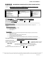
ENGINEERING CHANGE NOTICE (FIELD CHANGE NOTICE)
SUBJECT: Releasing the information of DR-ID300CL Application Software V8.1
(for Software licence unsupported version)
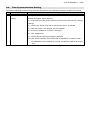
Design Change Reason
Action
Time frame
Product Improvement (*1)
Mandatory
Immediately
Process Improvement
Recommended (*2)
(by
)
Serviceability
Not required (Information only) (*1)
Next maintenance (*2)
Part Replacement
Other (
)
Upon failure
Corrective Action(*2)
At your convenience
Preventive Action
Not Applicable (*1)
Regulatory Compliance
Other( )
Other (
)
“1 corresponds to the New Function/Enhancement below whereas *2 to the Error Corrections.
Dept.: Quality Assurance Div. Medical Systems Business Div.
DATE: Apr, 07 , 2015
EDITED BY: Y.Baba
APPROVED BY: Y. Koyanagi
ORIGINATOR: K. Hayashi
AFFECTED PRODUCTS: DR-ID300CL
ATTACHMENT:
YES
NO
TOTAL PAGE (S):
66
RELATED INFORMATION: None
*********************************************************************************************************************************
DESCRIPTION OF CHANGE:
CL Application V8.1 for DR-ID300CL, including new functions and error corrections, is ready to be
released.
New Functions/Enhancement
1. Measurement (Distance, Angle)
2. Graphical Menu Option
3. Copy Image, etc.
Error Corrections
1. When images are re-sent after technologist name has been changed, only the first in-Study
image is sent to PACS.
2. Hang-up occurs when marker is used on Study screen..
3. Pre-image display sometimes takes time.
4. The relative sensitivity value becomes extremely low when "mis-exposure" is used during QC
reading, etc.
- APPLICABLE TO (Serial Nos. etc.) : DR-ID300CL Software V5.0/V6.0/V6.1/V6.2/V7.0/V7.1/V7.2/V7.3/
V7.4/V8.0(included HF)
- ESTIMATED WORK TIME:
0.0 HOURS
- SPECIAL TOOLS / INSTRUMENTS:
YES
NO
( Application software and tool is
- SUPPLY OF THE ARTICLES:
YES
NO not attached to this Rev.1 or later.)
IF YES, WHEN:
At the same time with this ECN
NAME / CODE:
DR-ID 300CL Application Software V8.1 / 114Y2150001B10 (DVD)
DR-ID 300CL PPU Application Software V2.1 / 114Y2150204B04.zip *1
QUANTITY:
1set of 1DVD
*1: Download from SIAS
- RETURN OF THE REPLACED PARTS TO FUJI:
YES
NO
The contents described or shown in our ECN documents and/or any information provided from FUJIFILM in verbal or written communication is intended for the
addressee and/or its organization. Transfer and/or copy distribution of the information without written consent of FUJIFILM is not permitted.
PAGE 1 of 2
K12N0028-6-J
ECN No. 2015-E-0029Rev.1
DOCUMENTS AFFECTED:
AFFECTED
DOCUMENTS
YES
NO
REV
CURRENT
ISSUED DATE
REV
NEW
ISSUED DATE
DETAILS:
See the attachment for details.
-
NOTE
1) Important information about SUPPLY OF THE ARTICLES:
Charge:
FREE OF CHARGE
UNTIL (mmddyyyy):
WITH YOUR CHARGE
NOT APPLICABLE
The contents described or shown in our ECN documents and/or any information provided from FUJIFILM in verbal or written communication is intended for the
addressee and/or its organization. Transfer and/or copy distribution of the information without written consent of FUJIFILM is not permitted.
PAGE 2 of 2
K12N0028-6-J
2015-E-0029aRev.1
Releasing the Information of DR-ID 300CL Application Software V8.1
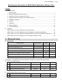
Contents
■
Main document:
1. Released items ............................................................................................................................ 1
2. Mainly Extended/Improved Functions.......................................................................................... 2
3. Correction of Errors Occurred in the Field ................................................................................... 3
4. Supported Version Information for Connected Device ................................................................. 8
5. Installation Procedure .................................................................................................................. 8
6. Cautions..................................................................................................................................... 17
7. Limitations.................................................................................................................................. 27
8. Lifting Limitations ....................................................................................................................... 27
9. List of Attachments..................................................................................................................... 28
■
Appendix:
DR-ID 300CL V8.1 ECN_Appendix-A Function Settings ................................................................. 29
DR-ID 300CL V8.1 ECN_Appendix-D List of Changes in Conformance Statement ........................ 58
DR-ID 300CL V8.1 ECN_Appendix-E Releasing DR-ID 300CL PPU Application Software V2.1 .... 59
DR-ID 300CL V8.1 ECN_Appendix-I List of Changes in System Config ......................................... 63
1. Released items
■
DR-ID 300CL
Parts number
Media
Number of
media
DR-ID 300CL Application Software V8.1
114Y2150001B10
CD
1
DR-ID 300CL Standard KIT V8.1
114Y2150003B10
CD
1
DR-ID 300CL Standard KIT (Lite) V8.1
114Y2150004B10
CD
1
DR-ID 300CL Standard KIT (Mobile) V8.1
114Y2150006B08
CD
1
DR-ID 300CL V8.1 Reference Guide 13th Edition
114Y2150052B11
CD
1
DR-ID 300CL PPU Application Software V2.1
114Y2150204B04
CD
1
DR-ID 300CL Menu Import Export Tool V6.8
114Y2150765B08
CD
1
Product names
<Reference> The operation of Console has been confirmed by using the following software.
■ Anti-virus software version
No.
■
Software name
1
Antivirus Workstation
2
Virus buster cooperate edition Plus
3
Symantec End Point Protection
Maker
Ver.
Remark
F Secure
V11.0
Japanese
TRENDMICRO
V10.6 SP2
Japanese
Symantec
V12.1
English
Maker
Ver.
Remark
EIZO
V4.3.1
Japanese
Monitor quality control software version
No.
1
Software name
RadiCS
1/64
2015-E-0029aRev.1
2/64
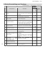
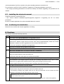
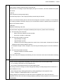
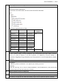
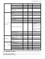
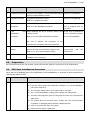
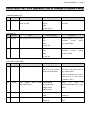
2. Mainly Extended/Improved Functions
*●: Standard function, ○: Option function, -: Not applicable
Installed
Function(*)
(distance, Distance between two points and angle
created by two lines can be measured on
the image.
2
Graphical menu options
3
Free Layout Print function Free Layout Print function
during Study
performed during Study.
4
5
6
Exposure area can be selected from an
abstract illustration of human body.
can
be
User (technologist) switching Technologist can be switched without
by barcode reading
starting the "Switch the user" dialog box
from the top-right menu of Console screen
but rather only by reading the barcode.
Pantomography
alignment format
top 3 top alignment formats for pantomography
images (15cm x 30cm) have been added.
Changing the Radiation field The Radiation field can be changed with
with Smart controller
the Smart controller.
7
Copying images
8
Applying
Virtual
Grid Virtual Grid function can be set ON/OFF
processing according to the per selector.
grid condition
Virtual Grid function can be turned OFF
automatically according to the image
analysis.
9
Connecting
IBA-designed Dose
Product Meter (DAP)
Exposed image can be copied to a
non-exposed menu.
with Connection with IBA-designed
Area (KermaX plus) is available.
Mobile
Measurement
angle)
Description
Lite
1
Developed Item
Standard
No
●
●
●
●
●
●
○
○
*1
*1
Chapter 1
-
●
●
●
○
○
○
*1
*1
*1
○
○
○
*1
*1
*1
●
●
●
Chapter 3
Chapter 5
Chapter 6
Chapter 7
Chapter 8
○
○
○
*1
*1
*1
●
●
-
DAP
Chapter 9
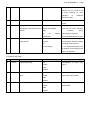
Expansion
of
exposure Log output item has been added.
result/mis-exposure log
●
●
●
11
D-EVOII
connection
●
●
●
model The connection with D-EVOII small model
(2430C) is supported.
Chapter 2
Chapter 4
10
small
AppendixA for
Reference
Chapter 10
Chapter 11
*1: As it is an expansion in existing options, application of the exiting option key is necessary.
2015-E-0029aRev.1
3/64
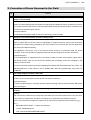
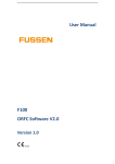
3. Correction of Errors Occurred in the Field
No
1
Content
When images are re-sent after technologist name has been changed, only the first in-Study
image is sent to PACS.
[Cause]
When V5.0 was implemented, technologist change became available per Study compared to previous
"per image". But there was a flaw in the SOPInstanceUID numbering processing which resulted in new
numbers only issued for option menus.
[Countermeasure]
Corrected the SOPInstanceUID so that new numbering is done per Study.
2
Hang-up occurs when marker is used on Study screen.
[Cause]
Memory region that is in the PC used for image display or image processing, opens in the cooperation
application at a certain timing (decided by OS). This results in PC to be busy and Console application
processing be halted temporarily.
The application alive-check, one of the functions inside Console, is performed under the above
condition. That is why operation is judged as abnormal and thus program is forced to shut-down.
[Countermeasure]
To avoid application to suddenly be busy, the cause to make PC under such condition (cause that is
preventing memory open by OS) should be deleted and processing should be managed by OS
memory control function.
Correction has been made so that when upgrading the installer SQL Server2008 from SP1 to SP3, the
MaxServerMemory of SQL Server is set to 256MB rather than the regulated Max value upon IIP
installation.
3
Pre-image display sometimes takes time
[Cause]
It takes 16 or more seconds to access to DB. The reason is unknown.
[Countermeasure]
In order to enable analysis, correction has been made so that log output is performed when DB access
time is prolonged.
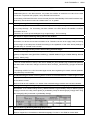
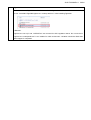
4
The relative sensitivity value becomes extremely low when "mis-exposure" is used during QC
reading
[Cause]
File name that is related to the mis-exposure specified menu becomes located at the very end when
"mis-exposure" is performed. Therefore, the sequence of menus becomes inverted upon QC.
(This occurs because the sequence changes not by menu but by image file name (routinexxx.yyy).)
E.g.)
SHAD./RELATIVE SENS. <- Subject mis-exposure
1 SHOT PHANTOM PLUS
LAG 1 IMG (FOR MEASUREMENT PREP)
2015-E-0029aRev.1
4/64
LAG 2 IMG (FOR MEASUREMENT)
SHAD./RELATIVE SENS. <-Generated due to mis-exposure (located at the end)
[Countermeasure]
Correction has been made so that the list sorted in the order of ImageNumber.
5
BR10001 error appears during MWM usage
[Cause]
Patient information linkage display fails to process and error appears when Length is 0 in the following
patient info tag.
(0010,21C0) PregnancyStatus
(0011,XX30) Blood type(ABO)
(0011,XX31) Blood type(Rh)
(0011,1060) Outpatient/inpatient
[Countermeasure]
Correction has been made so that other patient info can be displayed on the patient info link display
screen even when Length=0.
6
Disabling the startup recovery
[Cause]
See ECN “2014-E-0442 Releasing How to Restrain Startup Repair on Console PC” for further detail.
[Countermeasure]
Procedures described in the above ECN are now equipped in the installer so to be automatically
applied upon version upgrade or new installation.
7
When abdomen SU is exposed after "Chest SIT" exposure, a message asking whether or not to
recover appears on the pre-reading screen. When "OK" button is clicked, PC freezes.
[Cause]
Due to logic error in the exceptional processing, synchronization-waiting may occur leading to
deadlock.
[Countermeasure]
Corrected the deadlock so that exceptional processing will not occur.
8
VG processing cannot be performed on existing MPM code even by setting VG in the newly
created menu
[Cause]
Upon creating a new Menu B utilizing Menu A in User Utility, the image processing parameter of A is
not inherited when MPM code already exists in B.
As a result, if A has a VG parameter and B does not, VG parameter of B cannot be inherited. Thus VG
processing cannot be performed in B.
[Countermeasure]
Correction has been made so that VG parameter becomes inherited from A (copy source) to B (copy
destination) when all of the following conditions meet.
・ VGP parameter exists in the MPM code of A (copy source)
・ VGP parameter exists in the MPM code of B (copy destination)
9
AWS application does not start when WINDOWS is running
[Cause]
2015-E-0029aRev.1
5/64
Usually, log is collected after the Console shuts down. However, in the event of abnormal shutdown
owing to power off,etc. log is collected upon the next startup. Thus startup becomes suspended
because log collection processing and output of cooperation application log (CooperManagerOp.log)
overlaps.
[Countermeasure]
Different from AWS, DR-ID 300CL is designed to output only error log, without affecting the startup,
even when log collection and log output processing of cooperation application overlap.
Correction has been made not to output CooperManagerOp.log of the questioned cooperation
application because it is not needed for analysis.
Therefore, from V8.1 onward, procedures described in ECN “2014-E-0319 Releasing Measures for
Avoiding Console Startup Failure caused by Cooperative Application” is not required.
10
There are some tables of which values all become transferred into default when export is
performed with MenuImportExportTool.
[Symptom]
Under V7.4 or later environment, values in the MenuData.mdb-IrSizeAndPosition table all are
transferred to default when MenuImportExportTool export is performed.
[Cause]
The export processing of IrSizeAndPosition table is branched off intricately per version. We did not
take the above processing in consideration upon supporting V7.4.
[Countermeasure]
Correction has been made so that the value of IrSizeAndPosition table can be exported even in V7.4
or later.
11
Multi-language characters are corrupted on the User Utility technologist information setting
screen.
[Symptom]
Chinese, Korean and Chinese Traditional characters in the User Utility technologist information setting
screen of V7.3 or later are corrupted.
[Cause]
Function A which sets the font so that characters of each controller will not corrupt was too huge.
Therefore, we separated the technologist information settings part from function A to B. But we forgot
to change the call area from A to B.
[Countermeasure]
Performed font setting in the technologist information settings screen so that Chinese, Korean and
Chinese Traditional characters do not corrupt anymore.
12
SOPInstanceUID overlap
[Symptom]
An image including identical SOPInstance UIDs is created during Tomosynthesis reconstruction.
[Cause]
A unique value is created inside Console for CreateImageUID. This is because when calls are 255 or
more within a second, a same value becomes generated.
Since there are 7 calls per image, a same SOPInstance UID becomes generated if 36 or more images
are created within a second.
2015-E-0029aRev.1
6/64
[Countermeasure]
Corrected the internal counter from 255 to 65535.
13
VGP ON/OFF display for exposure menus other than Chest/Abdomen
[Symptom]
Overlay is displayed as ON even when VG processing is not performed.
[Cause]
Overlay is specified to be displayed as ON when VGP setting in menu is ON.
[Countermeasure]
The conditions to display overlay as ON have been changed as follows.
*Displayed as ON when all the following conditions meet.
14
・
VGP setting of menu is ON
・
Service settings of VGP is ON
・
VG option key is installed
Image does not appear in the Console image display area during continuous operation
[Symptom]
The following message appears and image does not become displayed on the image display area
when long-view exposure is continuously performed.
[ST31465] It will be treated as a regular image due to a
failure of provisional linkage.
[Cause]
Such symptom occurs when there is an error in the memory allocation for image display.
[Countermeasure]
Added a Release processing to the relevant Object and made corrections so that memory will not leak.
15
Image status sometimes does not become updated after exposure suspension
[Symptom]
Depending on the timing of exposure suspension, updating the image status of the suspended menu
sometimes fails and ShotReady lamp lights when menu is reselected.
[Cause]
Image status update sometimes fails due to exclusive processing flaw, depending on the suspension
timing.
[Countermeasure]
Correction has been made so that image status will surely be updated regardless of suspension
timing.
16
Exposure condition returns to APR default when changed in Tomosynthesis S
[Symptom]
After selecting a Tomosynthesis exposure menu and changing an exposure condition (kV, etc.), the
exposure condition returns to APR default value (the condition of pre-shot, if with pre-shot) whenever
condition of Tomosynthesis exposure menu (SID,Tomo/Incidence Angle,Exposure time) is changed
again in Console.
[Cause]
When the Tomosynthesis exposure menu conditions (SID,Tomo/Incidence Angle,Exposure time) are
2015-E-0029aRev.1
7/64
changed, menu registration is done by pre-set therefore returns to default.
[Countermeasure]
Corrected the system setting so that whether to notify the Tomosynthesis menu exposure conditions
by pre-set or individual can be switched.
Note that DR-ID 300 CL is configured to notify by pre-set, while DR-ID 900CL is so by individual.
17
Exposure cannot be performed even when shot SW is clicked.→"[MI11003] In the process of
starting exposure, time-out was occurred, and exposure has been cancelled." appears
[Symptom]
Exposure is unavailable even by clicking all shots and results in timeout.
[Cause]
The upper limit of the SQL User Connection count of Console is defined as 100. However, there are
occasions when counts tentatively exceeds 100. When DB access is tried in such situation, access
fails and error occurs.
[Countermeasure]
Corrected the upper limit of UserConnection counts from 100 to 200.
18
Operation becomes inefficient when image is acquired by displaying PID image during
reconstruction processing
[Symptom]
When PID image is displayed during Tomosynthesis reconstruction and image acquirement is
performed, the 2nd monitor screen becomes inactive.
[Cause]
Synchronization control between threads that generate images to be displayed is not adequate
resulting in deadlocked.
[Countermeasure]
Reviewed and corrected the synchronization control between threads so that operation inefficiency
such as hang-up will not occur.
19
The cradle LED lights a different selector color for an instance before Study starts
[Symptom]
For an instant, selector LED of the cradle lights the color that was selected right before Study-start and
then changes to the proper selector color.
[Cause]
The following procedures were taken before Study-start.
(1) Light the cradle LED with the selector color that was chosen in the previous Study.
(2) Select the selector together with the auto menu selection upon Study-start.
(3) Light the cradle LED with the selector color that was chosen in (2).
Therefore, just for an instant when waiting for procedures (1) to (3) to be completed, the cradle LED is
lit with the selector color that was chosen in the previous Study.
[Countermeasure]
Correction has been made so that the selected selector color is lit for the cradle LED before Study-start
when choosing the selector linked with the menu selection is completed.
*Other than the above, corrections made in DR-ID 300CL V8.0HF0001, DR-ID 800CL V8.0 and DR-ID 900CL
V8.0 also apply.
2015-E-0029aRev.1
8/64
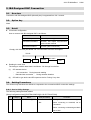
4. Supported Version Information for Connected Device
The versions of devices, which can be connected to DR-ID 300CL V8.1, are shown below.
(1)
FCR image reader
There is no change from the previous version in the connectable models of the FCR image readers and
their versions.
(2)
Control Unit
The following control units can be connected with V8.1.
-
MC
-
Connection with DR-ID 600: V6.3or later
・
Connection with DR-ID 700: V4.3or later
・
Connection with DR-ID 800: V2.1or later
・
Connection with DR-ID 1200: V1.3or later
CU
(3)
・
・
Connection with DR-ID200 Acselerate-Se: V3.11or later
・
Connection with DR-ID200 Acselerate-CsI: V4.5 or later
FSC V2.2 or later
PPU
Tomosynthesis Application Software which can be connected to V8.1 are V2.1 or later.
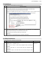
5. Installation Procedure
5.1.
Cautions concerning upgrading installation
No.
1
Cautions
Upgrading installation to DR-ID 300CL V8.1 can be performed only from the following versions.
*Including HF for each version.
・
DR-ID 300CL V5.0, V6.0, V6.1, V6.2, V7.0, V7.1, V7.2, V7.3, V7.4, V8.0
Data migration can be performed from the following versions.
*Including HF for each version.
・
DR-ID 300CL V4.0 *1
・
CR-IR 348CL V8.0, V8.1, V8.2, V8.3 *1
*1: See ECN “2013-E-0015_1 Releasing the Data Replacing Procedure from CR-IR348CL V8
and DR-ID 300CL V4 to DR-ID 300CL V7.0”
*Be sure to use MenuImportExportTool V6.8.
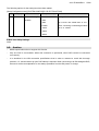
2
When upgrading at the institutions where the users are using the Retake Analysis function, the
2015-E-0029aRev.1
exposure result data file output function or the mis-exposed image comment function, collect the
logs by using the log storage function of the User Utility before upgrading. (Refer to step 5 of “5.2
Upgrading Installation”.)
3
Subsequently to the version upgrade, be sure to execute CopyReserveCode1FromMicroAs.bat
on the systems where a temporary countermeasure (setting the data of the previously configured
“ReserveCode1” to the first four digits of “Exposure_µAs”) has been implemented against an
error, which makes the communication value field for anatomical connection with Toshiba X-CON
different from the one used in V4. (Refer to step 27 and step 28 of “5.2 Upgrading Installation”.)
*The data of the first four digits of Exposure_μAs is set to ReserveCode1. Refer to ECN
No.2011-E-0364_DR-ID 300CL V6.1 ECN_Appendix-Z Correction of Errors Found in the Field for
the details of countermeasures for this error.
Note, however, that it is not required for institutions where CopyReserveCode1FromMicroAs.bat
has already been implemented at the time of upgrading the application software to this version
(V6.0 /V6.1)
4
Mammography exposure menu is added in V7.0. Since operation for keeping the usage of
Console without the Mammography menu is not supported except those shipped to the U.S. and
Canada, the Mammography exposure menu shall be added even to the device where the
Mammography function is not used. If this implementation was already done in the earlier
upgrading, no further operation is needed.
For the Mammography menu destined to the U.S. and Canada, see "Appendix-H Mammography
function hiding procedure" in this ECN.
5
Manual installation of the markers for mammography is required when using mammography
function on V7.0 or later. (Excluding US/Canada)
*Refer to “Appendix-A 5. Supporting CR mammography” in ECN No.2012-E-0291Rev.1 for
details.
6
Updating SKB Launcher is necessary.
For the systems where the SKB Launcher was installed before DR-ID 300CL V7.0 HF0001,
execute "19) Install SKB Launcher" in the installer media for V7.1 to reinstall SKB Launcher.
If this procedure is already performed, re-performance is not required.
7
The error “Patient names are right-aligned in the RIS tab on the Study list”.
Unlike other tabs, right-aligned patient names are displayed in the RIS tab. It was an error
included in the definition file for DR-ID 300CL V7.0 and earlier and this definition file is migrated
when upgrading the application software.
This error can be corrected by replacing the definition file with the new one in V7.1.
*If this procedure is already performed in re-performance in V7.2 or later is not required.
*Note: Customized settings reset after the new definition file is replaced. Therefore, take a note
of the customized settings for each tab and set them again after the new file is replaced.
<Other than Mobile>
[Installer DVD]:\program Files\FujiFilm\IIP\Config\CustomizeStudyListInfo.xml
⇒Overwrite the new file on
9/64
2015-E-0029aRev.1
10/64
C:\Program Files\FujiFilm\IIP\Config\CustomizeStudyListInfo.xml
<Mobile>
[Standard KIT(Mobile)]:\Mobile\Config\CustomizeStudyListInfo.xml
⇒Overwrite the new file on
C:\Program Files\FujiFilm\IIP\Config\CustomizeStudyListInfo.xml
<Before replacement>
<After replacement>
8
Destination of installed Wake On LAN
Do not change the default destination folder when installing "11) Install WakeOnLAN Application".
(Because the path of default destination is overwritten with the tool whose errors has been
corrected)
Default destination of installed WakeOnLAN: C:\Program Files\FujiFilm\WOL
9
SOP Class of supported DICOM Storage.
Modality Code is strictly checked during DICOM Storage since CR mammography has been valid
in V7.0. DE20001 error occurs when SOP Class is combined with unsupported Modality Code
and Storage is not enabled. If console is upgraded from V6.2 or earlier, refer to "ECN
No.2013-E-0043 Appendix-A 4. Supporting CR mammography (for other than Mammography
QC)”and confirm that setting complies with support environment.
10
DICOM Q/R setting.
Though DICOM Q/R reprint function(network image search)has been supported in V7.2, the V4.0
setting for Q/R is not transferred to new version during version upgrading. Therefore, new setting
for V8.0 is necessary.
Refer to "ECN No.2013-E-0185 Appendix-A 2. DICOM Q/R reprint (product name: network image
search software)" for setting procedures.
2015-E-0029aRev.1
11
11/64
Trimming size 17"x17" setting for study menu.
・
V7.0 or earlier :Trimming size 17"x17" setting is available
・
V7.1 or later
:Trimming size 17"x17" setting is not available
→*Note that 17"x17" is accepted only when trimming size is transferred to new version during
version upgrading. (Will be as 17"x17" during operation and no problem is posed. Setting in User
Utility is not available.)
When trimming size in study menu is set as “no setting” in V7.1 or later, system cannot judge if
trimming size is 17"x17" or of should refer to exposure menu.
Therefore, if user wants to reset transferred trimming size 17"x17", perform by following the below
procedure.
<Procedure to unlock trimming size>
1. Start User Utility, "Menu Setting ” button → Select "Study Menu" and Edit → "Trimming
settings(CR/DR)" button→Open "Trimming Size Settings" window.
2. Select any of the trimming size shown in the "Trimming Size" frame before pressing "OK"
button.
3. Also press "OK" button in "Study Menu Setting" window.
4. Go through same procedure as press "Menu Setting" button→Select "Study Menu", Edit→
"Trimming settings(CR/DR)"button→To unlock, open "Trimming Size Settings" window and
select the trimming size that was previously selected.
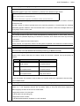
12
The default value when FPD-system cannot be identified upon image import from Media.
During Media rereading of DR-ID 300CL V4.0 or earlier, (0007,F009)"Device Name" tag is added
based on the below system setting. This tag is always set in V5.0 or later therefore the below
system setting is not used. Thus, the options are limited to relevant connection devices only in
V4.0
[Setup Configuration Item]-[SYSTEM CONFIG]-[5.CSL/IDT FUNCTION]
No.
Name
Value
Comment
: Default value
312
13
Media Set
Default FPD-System
BENEO
FDR-AcSelerate
CALNEO U/MT/MB
CALNEO-C
FDR D-EVO
FDR AcSelerate_CSI
CALNEO-C SQ/FDR D-EVO plus
CALNEO C mini
D-EVO plus C24
CALNEO HC SQ
Specifying the default value if
FPD-System cannot be
identified when the image is
retrieved from the media.
* If the device deleted before
version upgrade is still set, it is
replaced to the default value
"CALNEO-C".
Photometric Interpretation in the Service Class which was registered before upgrading has been
upgrade and changed into the MONOCHROME 2, but the change is not reflected.
Be sure to change to MONOCHOROME2 after deleting/re-registering the relevant Service
Class with the AE displayed beneath the Host Name in [Service Utility]-[Setup Configuration
Item]-[NETWORK CONFIG]-[ALL OTHER NODES].
14
Search conditions for MWM communication
If the version is upgraded from V7.3 or earlier to V8.1, search condition settings for RIS are not
taken over.
Set the settings again on the “Setting of RIS search condition” window after the upgrade.
2015-E-0029aRev.1
12/64
*The settings are taken over if the version is upgraded from V7.4 or V8.0 is reinstalled.
15
EI correction value of ExposureIndex function
V7.4 or earlier has taken over EI correction value by the upgrade.
However, EI correction value is overwritten without being taken over by the upgrade to V8.0.
When the version is upgraded to V8.1 at a facility customizing EI correction value, follow the
below procedure to manually take over the value.
1) Before the upgrade, copy and back up following file.
C:\Program Files\FujiFilm\IIP\Param\ExposureIndex.prm
2) After upgrading to V8.1, if Console Application is activated, end it.
3) Start the explore and open the folder of C:\Program Files\FujiFilm\IIP\Param.
4) Use text editor to open C:\Program Files\FujiFilm\IIP\Param\ExposureIndex.prm.
5) Refer to ExposureIndex.prm backed up by step 1), and reflect the place being customized for
a facility on ExposureIndex.prm of step 4).
6) Overwrite edited ExposureIndex.prm.
7) Start Console Application.
16
Handling of the error that unnecessary files (thmcopy) remain in an Image folder
With V7.3 or V7.4, unnecessary temporary files (thmcopy) may remain under an Image folder
under the following conditions.
・
In the case when AcSelerate and Calneo-U/MT/MB (Units which does not transmit preview
images to Console) is used to input images
・
In
the
case
when
“No”
is
selected
for
“1.IMAGE
MODALITY”
‐
“316:
EnableHighSpeedPreview” in Config
If the version is upgraded to V8.1 from V7.3 or V7.4 at the facilities applicable to the above
conditions, after upgrading they must use the wiping tool (Delete_thmcopy.bat) attached to
ECN“2014-E-0313 Releasing Measures for Preventing thmcopy File to Remain Inside Image
Folder in DR-ID300CL(V7.3/V7.4)” to erase the temporary files located under the Image folder.
* This error has been solved in V8.0. If the ECN mentioned above has been applied to V7.3 or
V7.4, the tool has to be erased after the version is upgraded to V8.1.
17
Patient information display linkage function
If the following setting file is customized in a facility using Patient information display linkage
function, be sure to backup the file previous to version upgrade and locate the backed up file to
the relevant folder after version upgrade is completed.
*Note that the following file will not be inherited upon version upgrade but file rather returns to the
factory default.
・
18
C:\FDRWeb\rmtDisp_PatientInfo\App_Themes¥PatientInfo.xsl
Remote image display function
If the following setting file is customized in a facility using Remote image display function, be sure
to backup the file previous to version upgrade and locate the backed up file to the relevant folder
after version upgrade is completed.
*Note that the following file will not be inherited upon version upgrade but rather returns to the
factory default.
2015-E-0029aRev.1
5.2.
・
C:\FDRWeb\rmtDisp_DisplayImage\web.config
・
C:\FDRWeb\rmtDisp_DisplayImage\App_Themes¥Display.css
・
C:¥FDRWeb\rmtDisp_DisplayImage\App_Themes\Display_Mobile.css
・
C:¥FDRWeb\rmtDisp_DisplayImage\App_Themes\Anotation.css
13/64
Upgrading Installation
1)
Start up the PC.
2)
After Console has started up, confirm that no studies are left in the “Waiting study”, “Waiting QA”, or
“Output Status” tab.
3)
- Studies in the “Waiting study” tab →
Finish or delete the studies.
- Studies in the “Waiting QA” tab
→
Finish QA.
- Studies in the “Output Status”tab
→
Output the studies or delete the output queues.
In the data editor, set Physician of Record (0008,1048) to hide it if it has been set to display it.
Refer to “6. Cautions‐19. Correcting the error of mixed incorrect character in the Physician of Record
AN” of this section.
4)
Perform
the
following
depending
on
the
institution’s
operational
situation
since
log
of
exposure/mis-exposure become deleted upon installation.
(ECN See No.”2” if “5.1.Cautions concerning upgrading installation” in this ECN.)
■
For institutions using Retake Analysis
(1)
Start up the User Utility.
(2)
Perform "Retake Analysis" function and on-time store logs.
(3)
Terminate the User Utility. Retake. (Terminate the User Utility while holding the <Shift> key to
terminate only the User Utility and not to restart Console.)
■
For institutions where the users are using the exposure result data file output function or the
mis-exposed image comment function.
(1)
Start up the User Utility.
(2)
Store the mis-exposure image log or exposure result log using the exposure result log storage
function.
(3)
(4)
Clear log by using exposure result log storage function.
Terminate the User Utility. Retake.
(Terminate the User Utility while holding the <Shift> key to
terminate only the User Utility and not to restart Console.)
5)
Terminate the Console and turn off PC.
6)
After confirming that the PC power if OFF, turn it ON and start Console. The starting screen is displayed
amid Console Application startup. Click top-left and then top-right of the screen within 3 seconds. (If
Console Application has started, terminate only Application by pressing <Shift> key+ system termination
and proceed to the next step)
7)
Service Utility opens. Terminate it and go back to the desktop.
8)
When “FUJIFILM” task remains on the task bar, right-click the task and select “End” to terminate it.
After the termination, wait around 5 seconds, and then perform the next step.
2015-E-0029aRev.1
9)
14/64
Press <Ctrl>+<Shift>+<Esc> key to start up the task manager and display the “Application” tab.
If the following programs are running, select them and click “End Process Tree”.
Click “OK” when the confirmation dialog appears.
・ CooperManager.exe
・ RemoteLoginChecker.exe
(*Terminate the following if mobile kit is used)
・ PPSMonitor.exe
・ SKBLauncher.exe
10) Exit the task manager.
11) Uninstall “Precise enlargement software”, “Free Layout Print software”, “Referral Viewing software”,
“Network Image Search software” or “QA ROI Measurement software” if any of them are installed.
* See Service Manual “Installation-Appendix (AppxIN)”-“Appendix 7 Uninstallation of AP” for further
procedures.
(Note)
As described in the Service Manual, use the CD for the installed software version to uninstall the precise
enlargement software.
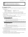
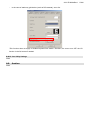
12) Insert the DR-ID 300CL V8.1 Application Disk into the DVD drive.
13) Press Windows key. Select “Computer” from start menu.
14) Open explorer and double-click DVD drive. Set menu of Console Advance appears. (Double-click
“Setup.bat” located right beneath DVD drive if command prompt does not start.)
15) Enter “5” and press the <Enter> key.
16) Select “IIP” in the “Programs and Features” window. Console is uninstalled.
17) The system returns to the setup menu. Enter “2” and press the <Enter> key.
18) “Select
Local”
menu
appears.
Select
the
language
that
2015-E-0029aRev.1
15/64
is
from
currently
set
Japanese/English(U.S.)/Other.
19) “Select Parameter” menu appears. Select the parameter type that is currently set from Monitor/Film.
20) When the “Welcome to the InstallShield for IIP” window appears, click the “Next” button.
21) When the “Ready to Install the Program” window appears, click the “Install” button.
(Note)
If the following error occurs, uninstall once more by following procedure 16).
Error1722 There is a problem with this windows
Installer package…
22) When the “InstallShield Wizard Completed” window appears, click the “Finish” button. Return to
command prompt and installation continues.
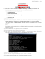
23) After the installation, the following message appears. Then, press “Enter” key to back to the setup menu.
**************************************
*****
Please reboot this system. *****
**************************************
Press any key to continue…
24) Install each linking application when necessary.
(Note)
Upon version upgrade in “ChineseTraditional” environment, the language selection in “Please select
information to setup” window installed during linking application becomes “ChineseSimplified” rather than
the previous “ChineseTraditional”. Therefore, be sure to select “ChineseTraditional” before installation
■
For the systems in which the Precise enlargement software has been installed, install the precise
enlargement software.
Enter “60)Install Precise Enlargement Function” and press the <Enter> key.
Refer to “Service Manual”-“Installation-Appendix(AppxIN)”-“Appendix 25. Precise Enlargement
Function”-“1.1Installing the Precise Enlargement Function
Software”-“4. Perform the following procedures.-● For V4.0” for further procedures. (Firewall settings
are not required when installing)
■
Install ROI measurement software if such function is necessary.
Enter “61” and press <Enter> key.
*Refer to “Service Manual”-“Installation-Appendix(AppxIN)”-“Appendix 48
QA ROI Measurement”
for further procedure.
■
Install referral viewing software if such function is necessary.
Enter “63)Install Referral Viewing Function” and press the <Enter> key.
*Refer to “Service Manual”-“Installation-Appendix(AppxIN)”-“Appendix 44 Referral Viewing” for
further procedure.
■
For institutions where the users are using the free layout print software, install the free layout print
software.
Enter “65)Install Free Layout Print” and press the <Enter> key.
2015-E-0029aRev.1
16/64
*Refer to “Service Manual”-“Installation-Appendix(AppxIN)”-“Appendix 30 Free Layout Print” for
further procedure.
■
When using Network Image Search function, install Network Image Search software.
Select “66)Install Network Image Search Function” and press “Enter” key.
*Refer to “Service Manual”-“Installation-Appendix(AppxIN)”-“Appendix 45 Network Image Search” for
further procedure.
25) The system returns to the setup menu. Enter “0” and press the <Enter> key.
26) The location of tube configuration data, which was stored in TubeConfig.ini file in V6.2 or earlier, has
been changed to Selector.mdb in V7.0. For this reason, set up the tube configuration data under the
selector settings in the Service Utility.
27) V7.0 enables LUT setup for the primary monitor and the secondary monitor separately. Set up the LUT in
the Service Utility if the system has the secondary monitor connected. ([Setup Configuration
Item]-[LUT]-[2nd Monitor LUT])
28) Click “(Root):\tools\FirewallSetting.bat” on the DR-ID 300CL V8.1 Application Disk.
* Models referring to “5.1. Cautions concerning upgrading installation”-“3” must perform the following
procedure after version upgrade installation.
29) Click“(Root):\tools\CopyReserveCode1FromMicroAs.bat” in the DR-ID 300CL V8.1 Application Disk.
30) When a confirmation dialog appears, press the “OK” button. (Twice in total.)
31) Remove the DR-ID 300CL V8.1 Application Disk from the DVD drive.
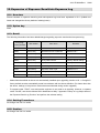
5.3. Replacing the default settings of exposure condition (XconParam.mdb)
(if necessary)
As the default values of exposure conditions have been changed to reliable CR console values from V7.0,
replace XConPara.mdb if necessary (Refer to “Appendix-A: Functional Settings 10. Revised default setting
for exposure condition (XconParam.mdb)” in ECN No.2012-E-0291Rev.1)
Caution: Replacing XConParam.mdb changes all the menu settings to default.
5.4.
Adding Mammography menu (excluding US/Canada)
Install the Mammography menu (Exposure menu and Image processing parameters).
See ECN “2012-E-0291 Rev.1 Appendix -B: Extended parameter convert tool”.
* See “5.1. Cautions concerning upgrading installation”-No.“4”.
* If it is already in the upgraded environment after V7.0, this is not a necessary implementation.
5.5.
Adding Tomosynthesis menu
If a Tomosynthesis menu is used after upgrading, add Tomosynthesis menu (Exposure menu and Image
processing menu).
For procedure of the addition, follow the ECN “2012-E-0291Rev.1 Appendix -B: Extended parameter convert
tool.”
* If the Tomosynthesis function is already used before the upgrading, this work is not necessary.
5.6.
Converting film to monitor
In institutions where standardize-less processing and monitor diagnosis are processed after upgrading,
2015-E-0029aRev.1
17/64
convert parameters from film to monitor using the extended parameter conversion tool.
For procedures, see ECN “2012-E-0291Rev.1 Appendix -B: Extended parameter convert tool.”
* If the image processing parameters for monitor are already used before upgrading, this procedure is not
needed.
5.7.
Installing the electronic manual
Update the electronic manual (PDF file).
* See “Service Manual”-“Installation-Appendix(AppxIN)”-“Appendix 8 Upgrading the AP” for further
procedures.
Be sure to reapply Application key when reinstalled electronic manual.
5.8.
Confirming the installation
Reboot PC and confirm that Console Application is running.
6. Cautions
This version includes the following cautions.
No.
1
Cautions
Error when using SynapseWebQuery on upgraded Console
The message “GetPixels failed with error: CDicomImgSrc::GetPixels...Failed to process image” may
appear and it disables image reference function when using SynapseWebQuery where the Console
application software has been upgraded from the old version the latest version.
In this case, reinstall the SYNAPSE client application.
2
Operation prohibited during RAID reconstruction
Do not use Console while RAID reconstruction is in process. Console may not work properly.
3
Shot switch disabled when connection to D-EVO is established
When the shot SW1 is turned ON/OFF while the connection to D-EVO is being established, the shot
may not be performed even when the Ready is lit.
In this case, select the menu again and continue the operation.
4
Wrong image orientation after reading study data output to media in non-FUJI original format
The orientations of the images might be changed when reloading image data that was output to media
without the Fuji original SOP Classes and then making some changes (such as menus).
Confirm image orientation after changing menus, and then execute the processing.
5
For DVI connection between PC and monitor
- Turn on the monitor before PC when connecting PC and monitor with DVI. The display size of the
Console screen may become small if the monitor is turned on after PC.
- The following message may appear when the PC was left untouched over 20 minutes and then
operation is resumed from the status that the monitor is OFF.
[OM30005] The screen resolution has been changed.
Please restart the system
Restart is not necessary because pressing the OK button on the dialog can continue the operation.
2015-E-0029aRev.1
6
18/64
Smaller time out value for PPS connection disabling operation
The study list of Console may be locked, which disables operations if the connection to PPS is not
established (due to a line disconnection, etc) under the condition of small time out value for the PPS
connection. To prevent this symptom, set up DICOM PSS as follows.
In the setting of DICOM PPS within a local Console (Service Class:Modality Performed Procedure Step,
Role:SCU), set the time out value to a default value “15” or greater.
7
DX Image Storage For Processing prohibited
The device, Synapse, connected to has not been supported although the support of the DI COM Digital
X-ray Image Storage - For Processing has been notified in the ECN No.2011-E-0290Rev.1 software
information of V6.0.
Therefore, do not set up DICOM Digital X-ray Image Storage - For Processing.
8
No device to output shuttering setting with the file attribute
Although V5.0 was equipped with a function to output the shuttering processing area as supplementary
information, no device can use the information so far. Therefore, be sure to set “Apply mask processing
to the image” to the setup item of Mask Processing in the registration of the other device (settings of
DICOM SCP) on Console in V5.0 or later.
9
Setting for marking stitched portions when making stitched images
Set up the following to mark the stitched portions on images.
([Setup Configuration Item]-[SYSTEM CONFIG]-[1. IMAGE MODALITY]-[70. Enable Marking Stitched
Image] - Select [Yes].)
10
At the time of new system installation
・The icon for the selector to set up is the one for 1M/2M (ST_NonTubeCRC.png) if StandardKIT(Mobile)
has been used. In this case, change it to the icon file for 0.7M (ST_NonTubeCRC_S.png)in the Service
Utility.
・Comparing to DELL PCs, HP PCs make bigger sound when registering IPs. Attach external speakers
only when they are necessary.
11
Troubleshooting the freeze occurring when Console is left untouched for a certain length of time
A symptom has been reported from the market. Console freezes when it is left alone for a certain length
of time after it is used.
Refer to ECN 2012-E-0229Rev.1 for details of the troubleshooting procedure that has been released.
12
Settings for using DX Storage for general studies (other then Mammography studies)
DR-ID300CL V7.0 enables settings under [1.IMAGE MODALITY]-[35:Modality Setup for Mammography
Image] in the Service Utility. Select [2:MG] in [35:Modality Setup for Mammography Image] when using
DX Storage(if [0:DX] is selected in [54:Modality Setup]).
13
(US /Canada only)Disabling Mammography function
Mammography function is not available for US/Canada.
Refer to “Appendix-H “Procedures to hide Mammography Function” in this ECN for further detail.
2015-E-0029aRev.1
14
19/64
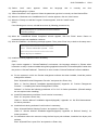
About displayed message [MD30009]
If Console operation is continued where the message [MD30009] left displayed on screen, the message
[MD30009] appears again when ShotSwitch is pressed, which disables image retrieve.
[MD30009] The conditions that do not allow an exposure to start have
been sent from an external device.
> Please check the exposure conditions of the external device.
The message [MD30009] appears when the exposure conditions become inconsistent between
Console and CU.
Provide a notice for users to prevent them from continuing operation on Console when the message
[MD30009] appears. Make the users be informed that it is required to confirm the message and then to
click [OK] to close it in such case.
15
Adjusting menu name layout
The number of letters of the menu names was adjusted by inserting spaces. In some cases, however,
layouts are not optimized depending on resolution of monitors, which makes menu item layout visually
undesirable.
Use spaces to adjust the menu name layout.
*Note, however, it is required to confirm how the system is operated in the institution to make a decision
whether or not to change the menu names for adjustment.
16
Network setup for Laptop PCs
(to correct the error that disables CR cassette processing on Mobile Console)
<Network binding setting>
Priority of the network bind setup for Laptop mobile PCs has been changed. Set up the priority as
follows
Priority
1
V7.1
Wireless connection to image Wired
local network
2
Wireless
connection
in-hospital network
3
V7.0 or earlier
Wired
connection
in-hospital network
connection
to
in-hospital network
to Wireless
connection
to
in-hospital network
to Wireless
connection
to
image local network
<Network>
In the case where CR cassette is used, at least one console needs to be registered in Service Utility “IDT CONNECTING”.
17
Migrating data from CR Console / AWS to be used in mammography QC
The data migrated from CR Console / AWS can be used in the mammography QC function of DR-ID
300CL V7.1. The supported versions are as follows. Refer to "ECN No.2013-E-0043 Appendix-C
Mammography QC DB convert tool" for further detail.
<Supported version of CR Console>
・CR-IR 348CL V8.3(including HF)
<Supported version of AWS>
・CR-IR363AWS Application Software V4.2 (HF included)
2015-E-0029aRev.1
18
20/64
Replacement defect of DX parameter after version upgrade V7.0 to V7.1
Cases of replacement defect of DX parameter may be detected when exposure menu in User Utility is
set after upgrading version from V7.0 to V7.1 or later. Therefore, if conditions meet, be sure to check DX
parameter with exposure menu import/export tool before setting the parameter.
<Conditions>
The following system setting change was made when V7.0 was upgraded to V7.1.
[Setup Configuration Item]-[SYSTEM CONFIG]-[1.IMAGE MODALIDY]
No.
35
Name
Modality Setup for
Value
Value
(V7.0)
(changed in V7.1)
2:CR
→ 0:MG
1:CR
→ 1:CR or 0:DX
Mammography Image
54
Modality Setup
<Symptom>
If conditions meet, DX parameters are replaced defectively when exposure menu is setup in User Utility.
<Parameters that are replaced>
・
ImageLaterality
・
PatientOrientation
・
AnatomicRegion
・
ViewCodeValue
・
ViewModifier
<Remedies>
Check the following DX parameters using the exposure menu import/export tool and edit where
necessary.
19
・
ImageLaterality
・
PatientOrientation
・
AnatomicRegionID
・
ViewCodeValueID
・
ViewModifierID1
・
ViewModifierID2
・
ViewModifierID3
・
ViewModifierID4
Correcting the error of mixed incorrect character in the Physician of Record AN
As A character "^" is inserted between first name and surname of the Physician of Record incorrectly, it
is necessary to perform setting in the data editor according to the following procedure.
1)
In the data editor, set Physician of Record (0008,1048) to hide it if it has been set to display
2015-E-0029aRev.1
20
2)
Upgrade the application software according to" 5.Installation Procedure".
3)
Set Physician of Record (0008,1048) to display.
21/64
Referral viewing and Registering DICOM connection confirmation Service Class of DICOM Q/R
reprinting
In referral viewing (V7.1 or later) and using DICOM Q/R reprinting(V7.2 or later), service is required to
register DICOM connection confirmation Service Class on Service Utility in the linking application. In
such case, if either one is already set with "Dicom Verification", do not set the other but rather used the
existing setting.
1)
Refer to Appendix-A "2.4.3. Service Class registration for DICOM connection confirmation " for
DICOM Q/R reprinting function.
2)
Refer to service manual Appx IN "Appendix 44 Referral Viewing 1.4.1 Setting the Connection of
Referral Viewing Software" for referral viewing.
21
Supported smart controller models
iOS devices which are supported by the smart controllers are the 5th generation of iPad mini and iPod
touch.
22
Action against communication error encountered during the start of Console under the remote
image display function
In the event of an error, the following icon appears. Selecting this icon allows the remote monitor display
information to be updated.
23
Setting 5.CSL/IDT FUNCTION 188.Mass Order Site Code Mapping Tag with the Service Utility
The following description is included in Service Manual of V7.2 and earlier.
188
Mass
Order
A maximum
of
49
Specifying to which tag the site identification code,
Site Code
one-byte characters.
entered using the screening examination ordering
Mapping Tag
(Blank)
function, is to be mapped.
* This is the setup item in V4.0 or earlier or V6.2 or
later.
Service Manual description is modified as follows to clarify the setup values.
2015-E-0029aRev.1
188
22/64
Describe the DICOM
Specifying to which tag the site identification code,
Site Code
tag values without a
entered using the screening examination ordering
Mapping Tag
comma.
function, is to be mapped.
Mass
Order
Enter
in
one-byte characters.
(E.g.) In case of mapping to (0032, 1033), enter
(Blank)
00321033.
* This is the setup item in V4.0 or earlier or V6.2 or
later.
24
iOS7 support (1): Using smart controller/remote image display
◆ Limitations of WebApplication shortcut (OS error)
<Detail>
An error (incorrect URI) occurs if four or more URI shortcuts of WebApplication are created on the Home
Screen.
<Remedy>
The number of URI shortcut of WebApplication should be up to three
25
iOS7 support (2): Using remote desktop connection
◆ PocketCloud
<Detail>
The connection information which was stored becomes cleared when updating to iOS7.Therefore,
cannot access to Server during Server communication.
<Remedy>
Set the PocketCloud connection by following the instructions in “10.5.1.2. WisePocketCloud connection
procedures” in ECN “2012-E-0107 Appendix-A Functional Settings“-“6.5.1. Wyse PocketCloud
Settings”.
26
Enabling “HDD writing flush at study finishing function” for remote operation
The study finishing time becomes slow when the following service setting is enabled. Be sure to check
the operation condition of the facility before setting this function.
[Setup Configuration Item]-[SYSTEM CONFIG]-[5.CSL/IDT FUNCTION]
(A.01-21)No.379 “Flush Disk Cache at Study Finishing”
27
Using both in-hospital wire-less and wired network
In V7.4 or later, if both wired and wireless are used for in-hospital network at the same time to
communicate with DICOM unit, communication may be necessary more than once to connect. Thus,
apply ECN“2014-E-0137” to Console with the concerned environment.
28
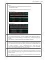
Screen becomes unintentionally under an image inversion processing state when image
switching is performed in the exposure list
<Symptom>
If the message display setting during image sending is set to “Yes”, a confirmation message appears at
the timing when a display image is switched by clicking (short pressing) the thumbnail part of the image
in the QA screen exposure list.
One to two seconds after the message is displayed, the QA screen results in an image inversion
processing state.
<How it occurs>
2015-E-0029aRev.1
23/64
Set the following setting to “Yes” in Service Utility.
[Setup Configuration Item]-[SYSTEM CONFIG]-[3.QA FUNCTION]
No.
Category
Name
Area
Comment
(◎:Default)
9
C.03.11
◎No
Setting whether to display a
Display When
Do not display
storage
Save
○Yes
upon previous or next Study
Display
shift / previous or next image
Alert
MSG
confirmation
dialog
shift/ QA termination
Startup Console. Start a Study that includes more than two menus from the Study list.
Display the exposure list.
Click (short click) the thumbnail part of an exposure menu different from the image displayed on the
image display area.
A confirmation message appears. One to two seconds after the message display, message responds.
⇒Screen becomes under an image inversion processing state.
<Remedy>
The above setting is recommended to be left as “No” (default).
Whenever setting it to “Yes”, be sure to inform the user on the <symptom>and <how it occurs> before
setting.
29
Initial General RIS Browser startup fails under in-hospital wireless network environment
<Under which environment it occurs>
An environment that meets both of the following conditions.
General RIS Browser function (option) is installed.
Connected wirelessly with in-hospital line.
<Symptom>
When initially running the General RIS Browser immediately after Console startup (including all startups
such as OS startup and startup after User Utility termination) under an in-hospital wireless network
environment, network always becomes offline and cannot be connected to RIS.
<Remedy>
(1) Check with the facility whether it is using in-hospital wire network.
If wire network is not required (always wireless connection with in-hospital line)
⇒Set the Wire LAN of OS network setting to “Disable”.
If wire network is required (uses both wire/wireless connection as needed)
⇒Perform following (2).
(2) Follow instructions described in ECN “2014-E-0137” for setting and confirmation.
<Remark>
Despite that the applicable scope of this issue is different from that described in ECN “2014-E-0137”,
remedy shall be the same from the aspect of “when switching multiple NICs in an in-hospital network,
communication fails”.
30
Time out during image input resulting from poor network
<Symptom>
2015-E-0029aRev.1
24/64
When inputting image with wireless small AP, radio condition becomes poor and image input process
stops owing to wireless small AP plug-out and the like.
Since there is no message or input status display during such condition, user often mistakes that system
has frozen.
<Cause>
Time out(180 sec) during image input(*).
*Preview image input or main image input after preview image is entered.
This is a conventional setting and can also be seen during wire connection. However, it is more likely to
occur during wireless connection owing to poor communication network, especially loose connection or
plug-out of wireless small AP.
<Remedy>
Explain the following to the user.
――――――――――――――――――――――――――――――――――――――――――
If preview/main image does not appear immediately after exposure, please check the following.
(1) For sites using wire connection
・
Cable connection between Console and MC.
・
Connection condition of cable itself .
(2) For sites using wireless connection
・
Signal strength of image
・
Signal strength of panel
・
Wireless connection settings (See ECN “2012-E-0100 DR-ID 300CL Precautions for Network
Settings for DR-ID 300CL Mobile Console”.)
If the signal strength is weak, strengthen it by removing the shielding object or shorten the distance,
etc.
(3) For sites using wireless small AP
・
Plugging condition of wireless small AP.
・
Same as (2).
If the main image is not displayed immediately, be sure to ask user to wait 180 seconds before rebooting
PC.
――――――――――――――――――――――――――――――――――――――――――
31
Interpretation of a value to be set to Tomo Time (0018,1480)
In V8.0, we have changed the interpretation of a value to be set to TomoTime (0018,1480).
V7.4 or earlier ) Total value of X-ray irradiation time
V8.0 or later ) Total exposure time (X-ray tube traveling time)
According to the above change, we have changed the setting of overlay display items as follows for a
new installation of V8.0.
[User Utility]-[Property Setting]-[Setup during a study 2]-[Setting for tomosynthesis view]
Prefix: Change to “Total Exposure Time” to “Tomo Time”
Overlay display items are taken over when the version is upgraded. Thus, when the version is
upgraded, discuss with users about changing display by taking a facility’s operation circumstances into
consideration.
2015-E-0029aRev.1
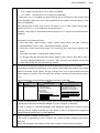
32
25/64
Installing ECN with tools in Application media
Install the ECN, which has tools and resources issued in 2014, in Application Software media.
Here are the folder configurations.
*“SEI umber” and “ECN number” will have numbers that will be stated later.
Here are the applicable SEI and ECN.
SEI description
SEI
ECN
Equipped
Version
33
13-004-377
DRCLC139_1
2014-E-0312
14-004-008
FCRC263
None
14-004-056
DRCLC175
2014-E-0033
14-004-063
DRCLA100
2014-E-0059
14-004-159
DRCLC181
2014-E-0137
14-004-264
DRCLA105
2014-E-0150
14-004-363
DRCLA110
2014-E-0219
14-004-214
DRCLA057
None
14-004-055
DRCLC182_2
2014-E-0083
14-004-614
DRCLC201_1
2014-E-0377
V8.0
V8.1
Precautions regarding energy subtraction and Tomosynthesis
In V8.0, System Config of energy subtraction and Tomosynthesis have been added. However,
there is no need to change in use with Acselerate. As “Appendix-A Function Settings 17.
Precautions Regarding Energy Subtraction and Tomosynthesis” in this ECN describes the details,
refer to it.
34
Initial error upon Console startup
<Symptom>
“[MD00001] Failed in initialization.” error appears upon starting up Consol.
<Remedy>
Check the event log. If it is a source =“DsmpuUserMode”, event ID=65535 error, check that the OS
serial port setting and Console setting are consistent.
35
Motion detection function of Smart-QA
Long view (MPM:770D) is not supported by Smart-QA motion detection function.
36
Limitation of “density optimization” function during arbitrary rotation
The density of image that was rotated with arbitrary angle cannot be optimized. (Button is inactive)
2015-E-0029aRev.1
37
26/64
TightVNC installer
From V8.1 onward, TightVNC installer is mounted in the Application Software installation DVD. Be sure
to use “\tools\VNC\TightVNC\tightvnc-2.6.4-setup-32bit.msi ” when installing TightVNC.
<Remark>
“tightvnc-2.6.4-src.zip” and “LICENCE.txt” are mounted for OSS regulation reason. Do not use them.
“tightvnc-2.6.4-setup-64bit.msi” is an installer for 64bit environment. Limitation should be lifted when
64bit support is completed.
2015-E-0029aRev.1
27/64
7. Limitations
Operational limitations in DR-ID 300CL V8.1 are as follows.
No.
1
Operation limitation
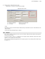
In clustering, the study information sometimes cannot be acquired.
→ If the study information cannot be acquired during the operation check after setup.
Start C:\Windows\System32\drivers\etc\hosts with the text editor.
Append the IP address and host name of a console at the end of a file for sharing the study
information to save the hosts (a single byte space between IP address and host name).
Following three CSLs are registered in this
example.
172.16.2.80 CSL
172.16.2.81 CSL-B
172.16.2.91 CSL-C
2
The trimming reference position, if changed from the x-ray tube panel in the Selene/Roots on
configuring the B4 trimming, is not reflected into Console menu.
→ Change the menu reference position from Console side.
<Remarks>
This symptom is not generated during the connection of VELOCITY.
8. Lifting Limitations
The following operation limitations have been lifted.
No.
1
Operation limitation
Remarks
ECN “2014-E-0374 Releasing the Information of DR-ID 300CL Application This limitation was
Software V8.0”-“7. Limitations”- “No.1”
Data cannot be output to media during integrated output processing in
clustering.
→Do not output data to a removal media during the integrated output
processing.
(The data is output to the media within the own device during the output
processing.
lifted in V6.1.
2015-E-0029aRev.1
9. List of Attachments
No.
Item
Document name
1
Function Settings
Appendix-A
2
List of Changes in Conformance Statement
Appendix-D
3
Releasing DR-ID 300CL PPU Application Software V2.1
Appendix-E
4
List of Changes in System Config
Appendix-I
28/64
2015-E-0029aRev.1
DR-ID 300CL V8.1 ECN_Appendix-A Function Settings
Index:
1. Measurement (Distance, Angle)................................................................................................. 30
2. Graphical Menu Option.............................................................................................................. 34
3. Free Layout Print in Study ......................................................................................................... 37
4. Switching Technologist by Barcode Reading ............................................................................. 39
5. Pantomography Top Alignment Format...................................................................................... 42
6. Changing Radiation Field with Smart Controller ........................................................................ 44
7. Copy Image ............................................................................................................................... 46
8. Applying Virtual Grid Processing According to Grid Usage Status............................................. 51
9. IBA-Designed DAP Connection ................................................................................................. 54
10. Expansion of Exposure Result/mis-Exposure Log ..................................................................... 56
11. D-EVO II small model connection .............................................................................................. 57
29/64
2015-E-0029aRev.1
30/64
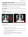
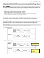
1. Measurement (Distance, Angle)
1.1.
Overview
Measurement function (distance, angle) has been mounted in Console as a QA function. The measured
results can be displayed on Console screen (1st Monitor) as reference information, but cannot be stored or
output to external device.
* Touch panel operation is not recommended for this function. Always use PC mouse.
1.2.
Option key
None
1.3.
■
Detail
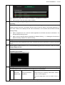
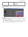
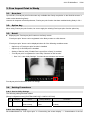
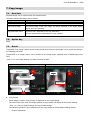
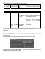
Starting up the measurement screen
The "Measure" screen can be started by clicking the "Measure" button in the in-study QA/Study list QA.
QA screen:
Measure screen:
“Measure menu” button
“Measure” button
Magnification
* “Measure” button is disabled in Tomosynthesis menu.
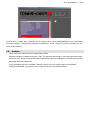
■
Distance measurement
The distance of any position within the image can be measured and the results can be displayed on the
screen.
・
Display specification of the distance measurement result:
–
Precision: Calculated to the second decimal place (value rounded off to the second decimal
place)
–
・
Unit: mm/inch(in accordance with service settings)
Can move the distance measurement result to any place within the image display region.
Measurement result can also be deleted.
・
Can set the color of line (common to angle measurement) in the Service Settings.
・
Can measure a maximum total of 16 points together with the angle measurement result.
・
Measurement result correction:
2015-E-0029aRev.1
–
31/64
If the magnification ratio can be received from Xcon, the measurement result is adjusted
according to the ratio in the case of magnified exposure.
–
In the case of general exposure, if SID and STD are received from Xcon, the measurement
result is adjusted according to the magnification ratio calculated with SID and STD. If SID and
STD are not received from Xcon, the measurement result will not be adjusted.
–
When the measurement result is adjusted, a "#" mark that describes adjustment completion
appears at the end of the measurement result.
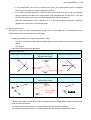
■
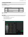
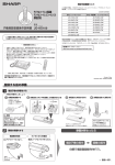
Angle measurement
An arbitrary angle (*1) and supplementary angle (*2) on the image can be measured and the
measurement result can be displayed on the image.
・
Display specification of the angle measurement result:
–
Precision: Calculated to the second decimal place (value rounded off to the second decimal
place)
–
・
Unit: Degree
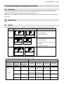
How angle measurement are described:
When two lines cross
2 lines subject to measurement
Measurement angle and
Display of measurement result
supplementary angle
B2
Α1
O
B1
Angle created
by two lines
Supplementary angle
Α2
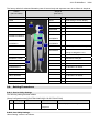
When two lines do not cross
2 lines subject to measurement
Measurement angle and
Display of measurement result
supplementary angle
Α2
Α1
O
Supplementary angle
Angle created
by two lines
B1
B2
・
Can move the angle measurement result to any place within the image display region. Measurement
result can also be deleted.
・
Can set the color of line (common to angle measurement) in the Service Settings.
・
Can measure a maximum total of 16 points together with the distance measurement result.
2015-E-0029aRev.1
1.4.
32/64
Setting Procedures
1.4.1. Procedure to install measurement function
Install the measurement function with DR-ID 300CL V8.1 Application Disk “62)
Install QA Measurement
(Application)”.
1)
Insert the DR-ID 300CL V8.1 Application Disk into the DVD drive.
2)
Press Windows key. Select “Computer” from start menu.
3)
Open explorer and double-click DVD drive. Set menu of Console Advance appears. (Double-click
“Setup.bat” located right beneath DVD drive if command prompt does not start.)
4)
Enter “62” (Install QA Measurement (Application))and press the <Enter> key.
5)
“Install QA Measurement screen ” window appears. Select the “QA Measurement”.
6)
“Welcome to the QA Measurement
7)
"Please select information to setup" window appears. Select the adequate language and monitor. Then
Setup Wizard”
window appears, click the “Next” button.
click the "Next" button.
8)
“Confirm Installation”
9)
“Installation Complete”
window appears, click the “Next” button.
window appears, click the “Close” button.
10) “Install QA Measurement”
window appears, click the “Close” button.
11) Returns to “Install QA Measurement screen” window. Click the “Exit” button.
12) The system returns to the setup menu. Enter “0” and press the <Enter> key.
13) “Press any key to continue...” displayed. Then press any key and close the Command Prompt.
14) Remove the DR-ID 300CL V8.1 Application Disk from the DVD drive.
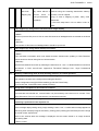
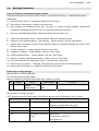
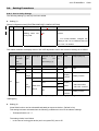
1.4.2. Service Utility Settings
Service Utility of Console Application:
The following setting has been added.
[Setup Configuration Item]-[SYSTEM CONFIG]-[7.CONFIG OPTION]
No.
21
Category
C.03.24
Area(:Default)
Name
Enable
QA Yes
Measurement
Comment
Enable/disable measurement function
No
Service Utility of Linking Application:
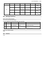
“DCT” settings window has been added. The following settings can be performed on “DCT” window.
Name
Zoom ratio for a click (%)
Area(:Default)
5/10/15/20/25/30/40/50
Comment
Zoom/reduction
ration
per
one
click
performing magnified/reduced display
Maximum zoom ratio (%)
200/300/400/500
Maximum zoom ratio for expanded display
Display unit
mm/inch
Unit of distance measurement
Color
Pink/Blue/Yellow/Purple/
Color of line
Orange
R,G,B value for each color
Pink:223,69,119
when
2015-E-0029aRev.1
33/64
Blue:9,167,189
Yellow:173,155,0
Purple:167,93,224
Orange:234,95,40
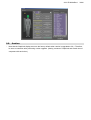
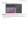
1.4.3. User Utility Settings
The "Measure" button can be set to display/hide from “Customizing the screen display” -> “QA function button
customize”.
1.5.
・
Caution
Note that the measurement result of this function is a reference value therefore the user must take
responsibility on how to judge such result.
・
PEM processing is performed in QA Measurement function of AWS but not in DR-ID 300CL measurement
function. (DR-ID 300CL does not apply PEM processing on images displayed on the Study screen or QA
screen therefore the measurement screen is designed to be consistent with such behavior.)
2015-E-0029aRev.1
34/64
2. Graphical Menu Option
2.1.
Overview
Up until V8.0, exposure areas were selected from text button. Now they can also be selected from the
abstract illustration of human body.
The terms used in this section are as follows.
Term
Classic
Graphical
Definition
Supplementary
GUI to select exposure part from the text button
GUI in V8.0 or
group
earlier
GUI to select exposure part from the abstract
V8.1 new GUI
illustration of human body.
2.2.
Option key
None
2.3.
Detail
The exposure part can be selected from the abstract illustration of the human body in the following screen.
・
Menu registration window
・
Window to change/add menu in the Study screen
・
Window to change menu in QA screen
・
User Utility Menu Setting screen
Screen image:
2015-E-0029aRev.1
35/64
The factory default for abstract illustration parts of human body and exposure menu is as follows in Graphical.
Classic
Graphical
(V8.0 or earlier)
(New V8.1)
NameSbcs
NameSbcs
HEAD
NECK
9
CHEST ABDOMEN
1
PELVIS
2
HEAD
1
NECK
2
CHEST
3
ABDOMEN
4
PELVIS
5
UPPER
UPPER EXTREMITY
3
EXTREMITY
LOWER
LOWER
4
EXTREMITY
6
-
No
EXTREMITY
Remarks
Initial setting of screen display
6
7
STITCH
8
-
FAVORITES
9
SPINE
-
Allocates to each part
-
Allocates to each part
-
No allocation as default
BREAST
-
No allocation as default
TOMOGRAPHY
-
No allocation as default
CONTRAST
-
No allocation as default
SOFT TISSUE
-
No allocation as default
LINAC GRAPHY
-
No allocation as default
QC/TEST
-
No allocation as default
ROUTINE
-
No allocation as default
5
THORACIC CAGE
PORTABLE
2.4.
7
8
No display when no stitch option
Locates
menus
Setting Procedures
[Setup Configuration Item]-[SYSTEM CONFIG]-[5.CSL/IDT FUNCTION]
400
Category
E.01.20
Name
Menu Screen Mode
Area(:Default)
Classic
Graphical
2.4.2. User Utility Settings
“Menu Setting” screen is as follows.
do
belong to categories 1 to 8
2.4.1. Service Utility Settings
The following setting has been added.
No.
that
Comment
Menu display mode setting
not
2015-E-0029aRev.1
2.5.
・
36/64
Caution
Note that the Graphical display returns to the factory default when version is upgraded to V8.1. Therefore,
be sure to customize after performing version upgrade. (Setting contents of Graphical and Classic do not
cooperate with each other)
2015-E-0029aRev.1
37/64
3. Free Layout Print in Study
3.1.
Overview
Up until V8.0, Free layout print function was only available after Study completion on the Work list screen. It
could not be done during Study.
However in response to field requirement, Free layout print function has been enabled during Study in V8.1.
3.2.
Option key
When using Free layout print function, be sure to apply the existing Free layout print function option key.
3.3.
■
Detail
Displaying the "Free layout print" button on the Study screen.
“Free layout print” button can be registered in the Study screen as a QA shortcut.
“Free layout print” button can be displayed when all of the following conditions meet.
・
Option key of Free layout print function is installed
・
Option key for DICOM print is installed
・
Setting of Service Utility “Enable Free Layout Print In Study” is enabled
・
“Free layout print” is registered in User Utility “Shortcut for QA function”
*
See “3.4.2. User Utility Settings” for where shortcut buttons are located.
Free layout print function itself does not change.
3.4.
Setting Procedures
3.4.1. Service Utility Settings
The following setting has been added.
[Setup Configuration Item]-[SYSTEM CONFIG]-[7.CONFIG OPTION]
No.
20
Category
C.02.13
Name
Area(:Default)
Comment
Enable Free Layout
Yes
Enable/disable Free layout print function
Print In Study
No
in Study
3.4.2. User Utility Settings
Set enable/disable for “Free layout print” in “Customizing the screen display” -> “Customization of the QA
2015-E-0029aRev.1
38/64
function shortcut button”.
Setting of *Service Utility “Enable Free Layout Print In Study” is enabled
3.5.
Caution
・
ShotReady does not perform when Free layout print function is running.
・
Image input in the background cannot be displayed when Free layout print function is running.
If such image needs to be displayed, terminate Free layout print function and Study screen, and then
reboot the Free layout print function.
2015-E-0029aRev.1
39/64
4. Switching Technologist by Barcode Reading
4.1.
Overview
Up until V8.0, “Switch the user” dialog had to be started from the menu at the up-right of screen whenever
switching technologist.
In V8.1, the workflow has improved so that technologist can be switched by reading the technologist barcode
(1D).
4.2.
Option key
None
4.3.
■
Detail
Screens subject to technologist switching by barcode reading
Screens of which technologist switching is available by barcode reading are as follows.
Switching with barcode
Screen enabled to switch user operation
■
Study registration screen
Enable
Exposure part selection screen
Enable
Study list screen
Enable
Study screen
Disable
QA screen
Disable
Barcode Format setting for operation switching upon barcode reading
Operation switches depending on the barcode format (see 4.4.1 Service Utility) that is read during
barcode reading.
・
In the case of technologist format
Switches to the technologist of which information is consistent
・
In the case of patient format
Registers the patient information.
・
In the case of unregistered format
Does not search.
・ If the format can not be identified if it is for a technologist or a patient (defined as same format for
technologist and patient)
Items with high priority can be searched by barcode setting in Service Utility.
■
Technologist information used for barcode reading
By selecting ON/OFF of user security (Service Utility
[1. IMAGE MODALITY]-[37. EnableUserSecrity]),
the search key can be switched during user switching upon barcode reading.
Search key
When security is ON
When security is OFF
Technologist user name
Technologist name (below
figure (2))
(below figure (1))
2015-E-0029aRev.1
40/64
User Utility: “Table Setting Menu”→“Technologist Information Setting”
1
2
* When security is OFF, the area framed with red dots does not appear and User Name/Password/User
group cannot be configured.
4.4.
Setting Procedures
4.4.1. Service Utility Settings
■ Change-points in “Barcode Setting-> 1D Barcode”-> “Barcode” screen.
・
Priority setting has been added
Items described at the upper part of the list are preferentially used as the Study conditions.
・
“Purpose” field for format has been added
“Barcode” screen
(3)
(1)
(1) UP Button:
(2)
Raise the priority.
(2) DOWN button: Lower the priority
(3) “Purpose” field for format: Displays the format purpose set in the "Barcode Format" screen.
-> “0”(Patient ID) or “1”(User Name)
2015-E-0029aRev.1
■
41/64
Change-points in “Barcode Format” screen
・
Setting items of “Purpose” for format has been added.
“Barcode Format” screen
(1)
(2)
(1) Patient ID (Default):
Patient ID or Accession No.
(2) User Name:
Technologist Name
* Note:
Depending on the type of barcode reader, characters may not be able to be set for “Start Character” and
“Stop Character”.
In such case, set the “Barcode Type” to “Others”.
4.5.
・
Caution
After version upgrading, always be sure to set in the Service Utility the same priority and purpose of
format as the prior version.
・
If you find a format of which “2” is displayed in the “Purpose” field of “Barcode” screen after version
upgrade, be sure to delete the relevant format.
(This is because facilities that migrated from CR Console may find "2" in the field but DR-ID 300CL does
not support "2".)
2015-E-0029aRev.1
42/64
5. Pantomography Top Alignment Format
5.1.
Overview
A blank margin appeared at the top of film when pantomography image (15cm x 30cm) was film printed.
Therefore, we added formats (3 patterns) to top align images in V8.1.
Specification of the additional format is similar to that of CR Console. Note that DR images are also subject to
this format.
5.2.
Option key
None
5.3.
Detail
The following three patterns of top alignment format (hereinafter, expansion format) have been added.
Film Size
Format (film characters are one example)
10”x14”
Condition for enabling
・ Expansion format output to 10”x14”
film is enabled
・ Single format output
8”x10”
・ Expansion format output to 8”x10”
film is enabled
・ Reduction output to 8”x10” film is
enabled
・ Single format output
10”x12”
・ Single format output
The relation of system setting and the film format to be output.
SYSTEM CONFIG (4.PRINTER)
64: Enable
Raduce to
8x10 Film
Output options
88: 15x30
ExFormat
For 14x10
Film
89: 15x30
ExFormat
For 10x8
Film
1st option
2nd option
3rd option
4th option
Yes
Yes
8”x10”
10”x12”
10”x14”
14”x17”
(ExFormat)
(ExFormat)
(ExFormat)
10”x12”
10”x14”
8”x10”
14”x17”
(ExFormat)
(ExFormat)
8”x10”
10”x12”
10”x14”
14”x17”
(ExFormat)
(ExFormat)
10”x12”
8”x10”
10”x14”
14”x17”
Yes
No
Yes
No
No
Yes
No
2015-E-0029aRev.1
43/64
(ExFormat)
Yes
Yes(Invalid)
Yes
No
No
10”x12”
10”x14”
(ExFormat)
(ExFormat)
10”x12”
10”x14”
(ExFormat)
(ExFormat)
10”x12”
10”x14”
14”x17”
10”x14”
14”x17”
No
Yes(Invalid)
14”x17”
14”x17”
(ExFormat)
No
No
10”x12”
(ExFormat)
5.4.
Setting Procedures
5.4.1. Service Utility Settings
The following setting has been added.
[Setup Configuration Item]-[SYSTEM CONFIG]-[4.PRINTER]
No.
88
89
Category
G.02.34
G.02.35
Name
15x30
ExFormat
Whether or not to output expansion
For 14x10 Film
No
format to 10”x14” film
15x30
Yes
Whether or not to output expansion
No
format to 8”x10”film
5.4.2. User Utility Settings
None
None
Caution
Comment
Yes
ExFormat
For 10x8 Film
5.5.
Area(:Default)
2015-E-0029aRev.1
44/64
6. Changing Radiation Field with Smart Controller
6.1.
Overview
The Radiation field information can now be changed with Smart controller in V8.1.
6.2.
Option key
When using Smart controller function, be sure to apply the option key of the existing Smart controller function.
6.3.
Detail
The following functions have been added to the Smart controller.
■
Displaying the Radiation field information on the exposure menu
Displays the following Radiation field information that is set in the exposure menu.
・
Radiation field size
・
Exposure standard position
・
Exposure orientation (expressed by length and width of display size)
Radiation field information column
■
Changing the Radiation field information
The Radiation field information of arbitrary unexposed menu can be changed with the Smart controller.
The following Radiation field change dialog appears when an unexposed menu is selected and the
Radiation field information column is clicked. The Radiation field size, orientation and exposure standard
position can be set in the Radiation field change dialog.
2015-E-0029aRev.1
6.4.
45/64
Setting Procedures
6.4.1. Service Utility Settings
None
6.4.2. User Utility Settings
None
6.5.
・
Caution
Equivalent to the Radiation field setting in Console, the range of selectable Radiation field information
that can be set with Smart controller differs depending on technique/function.
・
Equivalent to the Radiation field settings in Console, the Radiation field settings of the following menu
cannot be changed.
When Radiation field setting is tried to be changed, a message indicating that
change cannot be performed appears.
・
–
IP registered menu
–
A split stitch exposure menu
The Radiation field setting of Console and Smart controller become synchronized. (When setting of
Console is changed, the changed contents are reflected to Smart controller. When setting of Smart
controller is changed, the changed contents are reflected to Console.)
2015-E-0029aRev.1
46/64
7. Copy Image
7.1.
Overview
Exposed image can be copied to the non-exposed menu.
The terms used in this section are as follows.
Term
Definition
Copy image
A newly created image by copy operation
Copy source image
The source image of the copy image. The image displayed on the image display
region upon copy operation.
Copy destination menu
Exposure menu applicable to the copy destination
The non-exposed menu selected during copy operation.
7.2.
Option key
None
7.3.
Detail
“Duplication of an image” button can be located as QA shortcut button and image can be copied according to
the following procedure.
("Duplication of an image" button can be located on the image region operation area of Mobile spec wide
GUI.)
* See “7.4.2. User Utility Settings” for shortcut button location.
Before copy
After copy
(1) Choose the image to
be copied
COPY
(3) Select the copy
destination menu
Copy marker
(2) Select the copy button
■
Copy marker
When image is copied, "Copy marker" is displayed on the copied image.
The initial value of the color and display position of copy marker can be set in the service settings.
* See “7.4.3. Service Utility Settings” for copy marker settings.
The following operation can be performed for the copy marker in the QA marker setting window.
・
Position adjustment
2015-E-0029aRev.1
■
・
Color change
・
Rotate/Reverse
47/64
Precautions when copying images
If the copy destination menu meets either of the following conditions, image cannot be copied.
・
Exposed
・
IP registered
Menus that can be specified to the copy source or copy destination are only the following functions.
・
RT
・
TM
・
PS
Processings applied to the copy image (whether to inherit the copy source processing or apply the copy
destination processing) is as follows.
* ○: Inherit source △: Conform to User Utility settings
Category
Items
Copy
Copy
source
destination
Device correction
FPD device correction
○
GPR
GPR
○
Exposure
Rotate/Reverse
○
parameter
EDR
○
Function
○
Filing mode
○
Radiation field size/ standard
position
○
Distribution code
○
Image pixel density (for CR
○
exposure)
Film format
○
Film output count
○
X-ray tube/Technique code
Eit *for DI warning
Image
○
position
(center/right-justified/left-justified)
Film character string
Reading sensitivity shift (for CR
exposure)
○
○
○
○
Film standard orientation
○
Film edge
○
Remarks
2015-E-0029aRev.1
Film size
○
Number of division exposure
○
Name of code issuer
○
Reading mode (for CR exposure)
Sensitivity level for velocity (for
CR exposure)
○
○
Fill-up density
○
GA/GS
○
S/L value
○
FCR
48/64
image
processing
○
parameter
FNC/CRF parameter
○
VG parameter
○
VGP ON/OFF
○
Marker/Annotation
△
△
Image processing
Auto&manual
parameter
blackening
region
inherits that of the copy
Blackening processing settings
source.
○
Only
density
setting
applies that of the copy
destination.
Chest wall region fill
○
Trimming settings
△
Arbitrary angle rotation
○
Image
laterality/
Patient
orientation
DX parameter
Anatomical region
View code/View modifier code
sequence
S/L
allowable
value
7.4.
△
○
○
○
S/L allowable value
○
Left/Right reverse marker
○
Mis-exposure information
○
Mammography positioning
○
Smart-QA
○
Study information (including ID)
○
Setting Procedures
7.4.1. Service Utility Settings
The following setting has been added.
2015-E-0029aRev.1
49/64
[Setup Configuration Item]-[SYSTEM CONFIG]-[7.CONFIG OPTION]
No.
19
Category
C.02.20
Area(:Default)
Name
Enable Copy Image
Yes
Comment
Enable/disable the image copy function
No
[Setup Configuration Item]-[SYSTEM CONFIG]-[5.CSL/IDT FUNCTION]
No.
394
Category
C.02.21
Area(:Default)
Name
Copy
Marker
Position [%] (X\Y)
12\15
Comment
Copy
marker
embedded
position.
xxx\yyy
Specify the marker center in percentage
format. Maximum up
based on the relative position of X and Y
to 7 digits.
axis within the trimming frame.
Specify
in
*Up-left is the original point. 0 to 100 is
divided with "\" mark. The former figure
is the setting for the X axis relative
position while the latter is that of Y axis.
395
C.02.22
Copy Marker Color
0:White-Black
Color setting for character/background
(Fore
1:White-Clear
of copy marker
Color)
Color-Back
2:Black-White
3:Black-Clear
The copy marker “CopyMarker.bmp” becomes installed in “C:\Program Files\FujiFilm\IIP\Config” folder. As
done with usual markers, edit the copy marker according to customer requirement. Edit method is same as
usual marker.
7.4.2. User Utility Settings
Whether or not to inherit the information of trimming and marker annotation from the copy source to the copy
image is set per item.
The following setting has been added to “Property Setting”->“Setup during a study2” screen.
*Be sure that Service Utility “Enable Copy Image” setting is enabled.
“Customizing the screen display”->“Customization of the QA function shortcut button” screen. Set the
“Duplication of an image” button to enable or disable.
*Be sure that Service Utility “Enable Copy Image” setting is enabled.
2015-E-0029aRev.1
50/64
For wide GUI of mobile spec, “Duplication of an image” button can be displayed/hidden from “Customizing
the screen display”->“image region operation customization” screen. (Figure of image is omitted since it is
same as QA shortcut).
7.5.
Caution
・
Image cannot be copied during six-image display mode.
・
Exposure results are outside the scope of copy. The exposure results tag of copy image becomes empty.
・
If menu of which exposure results are linked is specified as the copy destination, the combination of result
and image becomes inadequate.
・
Copy processing cannot be canceled. Therefore, specify the mis-copied image as mis-exposure.
・
As like normal marker, copy marker is not subject to Service Utility backup/restore.
2015-E-0029aRev.1
51/64
8. Applying Virtual Grid Processing According to Grid Usage Status
8.1.
Overview
Up until V8.0, once Virtual Grid function is activated, this function becomes applied to images that actually do
not require such function, which results in an image with contrast too high. In order to improve the above
issue, the following has been implemented in V8.1.
・
Enabled to set Virtual Grid function active/inactive per selector.
(Under the assumption of moving grid system (DR system))
・
Enabled Virtual Grid function to be turned OFF automatically according to the image analysis.
(Under the assumption of stationary grid system (DR cassette))
Also enabled VGP parameter to be adjusted on image even when Virtual Grid function is OFF. This is in
response to the request from a joint study site. (This setting shall be opened only to joint study sites)
8.2.
Option key
When using Virtual Grid function, be sure to apply the option key of the existing Virtual Grid function.
8.3.
Detail
The difference of Virtual Grid processing flow between V8.0 and V8.1 is as follows.
■
Processing flow in V8.0
Fixed grid
GPR
VG
Perform GPR
With grid lines
VG processing
-> image with contrast too high
Moving grid
GPR
Without grid lines
■
VG
No GPR
VG processing
-> image with contrast too high
Processing flow in V8.1
Fixed grid
(Image
analysis)
GPR
No VG
Perform GPR
With grid lines
Detects grid and does
not perform VG.
VG
Moving grid
(Setting
determination)
VG
GPR
Without grid lines
No GPR
No VG
Complies with selector
setting.
VG setting is OFF in
this example.
2015-E-0029aRev.1
8.4.
52/64
Setting Procedures
8.4.1. Service Utility Settings
The following settings (1) and (2) have been added.
■
Setting (1)
[Setup Configuration Item]-[SYSTEM CONFIG]-[7.CONFIG OPTION]
No.
Category
356
C.03.23
Name
Area(:Default)
Comment
Enable Virtual Grid
Yes
Whether or not to allow VG edit on QA
Editing when use
No
screen.
X-ray Grid
*
For normal facilities, configure this
setting to “No”. For co-research sites, set
it to "Yes", as needed.
The relation between the display status of QA VGP adjustment button and the above settings is as follows.
Condition
Option
Setting to
Image
activate
type
Technique
VG
Display status
Whether or not to
Setting
apply
(1)
VG
VGP
mAs[VG]/kv[VG]
Hide
Hide
processing (*1)
function
None
‐
‐
‐
‐
‐
OFF
‐
‐
‐
‐
CR
‐
‐
‐
image
WS,ES,TO
Yes
ON
DR
image
‐
Yes
Other than
above
‐
Yes
No
Yes
No
No
Display
inactive
Display
active
Display
inactive
*1:
Display inactive
Display
VGP ON: Active
VGP OFF: Inactive
Display inactive
Whether or not to apply VG processing with option key or service settings (including the below new
"Settings(2)")
■
Setting (2)
Virtual Grid function can be activated/inactivated per exposure device. (Default is On)
This setting becomes activated when the following conditions are met for the selector settings.
・
TechniqueCode is not "-1".
The setting criteria is as follows.
・
In the case of moving grid device (such as system DR), set to Off.
2015-E-0029aRev.1
・
53/64
In the case of stationary grid device (such as DR cassette), set to On.
*This function does not apply to Studies imported from media. Therefore, be sure to turn OFF the VG
function in the QA screen if needed.
8.4.2. User Utility Settings
None
8.5.
None
Caution
2015-E-0029aRev.1
54/64
9. IBA-Designed DAP Connection
9.1.
Overview
Connection with IBA-designed DAP (KermaX plus) is supported from V8.1 onward.
9.2.
Option key
None
9.3.
■
Detail
Connection configuration
How to connect with IBA-designed DAP is as follows.
Item
Detail
Connection protocol
Special IF protocol (*)
Connection hardware
RS-232C half duplex asynchronous
communication method
Connection method
RS-232C (direct connection)
*Comply with "KermaX plus Model 120-131 HS/RS485 Interface Description"
TCP/IP
FPD
■
MP
Console
RS-232C
DAP
Reading the area dose
The timing to read the area dose is as follows. *No change from before.
(1)
CR cassette device:
・
N-N connection:
During barcode reading
・ Barcode-less connection:
(2)
9.4.
During cassette insertion
CR built-in type device and DR exposure device: During X-ray shot
Setting Procedures
This section only describes the difference compared to the conventional DAP connection settings.
9.4.1. Service Utility Settings
The following setting has been added.
[Setup Configuration Item]-[SYSTEM CONFIG]-[5.CSL/IDT FUNCTION]
No.
396
Category
B.05.10
Name
DAP Device Type
Area(:Default)
Comment
0:VacuDAP
Setting of DAP connection model type.
1:IBA
When connecting to VacuDAP, set to
"VacuDAP".
When connecting to IBA-designed DAP,
set to "IBA".
2015-E-0029aRev.1
55/64
The following options for the setting item have been added.
[Setup Configuration Item]-[SYSTEM CONFIG]-[5.CSL/IDT FUNCTION]
No.
397
Category
B.05.8
Name
DAP
Baudrate
Serial_TX
Area(:Default)
0:1200
Comment
Setting of DAP serial forwarding rate
1:2400
2:4800
No.4,5 and 6 are added items in V8.1.
3:9600
When connecting to IBA-designed DAP,
4:14400
set to "6:38400".
5:19200
6:38400
9.4.2. User Utility Settings
None
9.5.
Caution
・
Mobile specifications do not support this function.
・
Only one DAP is connectable. When this connection is performed, other DAPs cannot be connected
concurrently.
・
It is described in the IBA connection specifications that in order to measure a result with thorough
precision, 15- minutes-warm-up upon DAP startup is required. When connecting to an IBA-designed DAP,
be sure to receive an explanation on the startup procedure from the IBA person in charge.
2015-E-0029aRev.1
56/64
10. Expansion of Exposure Result/mis-Exposure Log
10.1. Overview
Record contents of exposure result log and mis-exposure log have been expanded in V8.1. (Added new
items and changed the factory default of existing items).
10.2. Option key
None
10.3. Detail
The following information has been added/changed regarding exposure result and mis-exposure log.
"EntryFlag"
Factory default
・
Tab number
Item name
Remarks
TRUE
(0018,0060)
KVP
Added in V8.1
TRUE
(0018,1110)
Distanse Source to Detector
Added in V8.1
TRUE
(0018,1111)
Distance Source to Patient
Added in V8.1
TRUE
(0018,1150)
Exposure Time
Added in V8.1
TRUE
(0018,1151)
X-ray Tube Current
Factory default change
TRUE
(0018,1152)
Exposure
Factory default change
TRUE
(0018,6000)
Sensitivity
Factory default change
TRUE
(0018,8150)
Exposure Time in μS
Added in V8.1
TRUE
(0018,8151)
X-Ray Tube Current in μA
Added in V8.1
TRUE
(0018,700A)
Detector ID
Added in V8.1
Added items described as above are automatically installed upon upgrading version to V8.1. Changes in
factory default are also automatically made in accordance with the above definition. (For items other than
the above, settings of the previous version becomes inherited during version upgrade.)
・
To operate under "TRUE", user and service engineer do not need to do anything. However, to operate
under "FALSE", see Service Manual "MU: Maintenance Utility"-"Appendix E Setup of Log Output Items of
the Exposure Result Log Function" and perform the relevant setting.
10.4. Setting Procedures
No change from V8.0 or earlier.
10.5. Caution
No change from V8.0 or earlier.
2015-E-0029aRev.1
57/64
11. D-EVO II small model connection
11.1. Overview
V8.1 has become connectable with the following small model in the line of second-generation cassette DR
(D-EVO II).
・
Device: CsI
・
Size: 24cmx30cm (2430C)
11.2. Option key
None
11.3. Detail
・
V8.1 is connectable with the following panels.
-
・
D-EVO II 2430C (DR-ID 1213SE)
During Memory Exposure Mode, receiving up to 200 images from each panel in a lump is possible.
(Up to 100 images with 14"x17" and 17"x17" panel)
・
Usable Trimming sizes for each Image size are as follows.
Image size
24cmx30cm
・
Usable Trimming size
8”x10”, 18cmx24cm, 7”x8”, 7”x10”, 5”x8”
Image processing parameters for small models can be preset through User Utility like other existing
panels.
11.4. Setting Procedures
11.4.1. Service Utility Settings
For small model connection, set "Device Type" of "Device Setting" to "CALNEO Smart C/D-EVO II C".
11.4.2. User Utility Settings
For setting image processing parameter while the small model is in use, set "Panel Type" of "Menu
Setting"-"Exposure Parameter 1"-"Image Processing Parameter Setting" to "CsI-2"
11.5. Caution
・
As the D-EVO II small model does not support Long-view exposure, its operation is restricted.
2015-E-0029aRev.1
58/64
DR-ID 300CL V8.1 ECN_Appendix-D List of Changes in Conformance
Statement
No changes from DR-ID 300CL V8.1 Conformance Statement.
2015-E-0029aRev.1
59/64
DR-ID 300CL V8.1 ECN_Appendix-E Releasing DR-ID 300CL PPU
Application Software V2.1
1. Overview
PPU Application Software V2.1 for DR-ID 300CL V8.1 or later has been released.
This ECN provides the upgrading procedure for it.
2. Released items
Product name
Part number
Media
Number of
media
DR-ID 300CL PPU Application Software V2.1
114Y2150204B04
CD
1
3. Applicable version
V2.1 is applied to the following versions.
Applicable version
Software
PPU Application Software
V2.0
V2.1 (in the case of reinstallation)
4. Changes in PPU V2.1
The new features of PPU V2.1 are as follows.
No.
1
Features
Details
Distance correction for Tomosynthesis The distance between the detector and the examinee is large in
reconstructed image
Tomosynthesis exposure. Therefore, the size on the detector
becomes expanded compared to the real size. This correction
processing is to make the size of image close to real size by
adjusting it to the size of the exposure surface during
reconstruction image generation. (This correction processing
is called "Distance correction".)
5. Upgrade procedure
The procedure for upgrading the PPU from V2.0 is shown below.
The same procedure also applies to reinstallation of V2.1.
1)
Start up the PC.
2)
Insert the “DR-ID 300CL PPU Application Software V2.1 (114Y2150204B04)” CD into the DVD drive.
3)
The “Autoplay” dialog opens. Click “Open folder to view files”.
2015-E-0029aRev.1
60/64
4)
The “114Y2150204B04(D:)” dialog opens. Double-click “Setup(.bat)”.
5)
The setup menu appears. Input “7” and press the <Enter> key. (Install/Update PPU System)
6)
Input “1” and press the “Enter” key. (DR-ID 200)
7)
The system returns to the setup menu. Confirm that “PPU Application installation completed” is displayed
directly before the displayed menu.
8)
Input “15” and press the <Enter> key. (Set Up Distance Correction Parameter for reconstructed image)
*Default setting is "Do not apply distance correction". This is to make the operation similar to that of the
existing system.
9)
Input “1” (Yes) to apply distance correction (display with real size) or “2” (No) when not applying
distance correction. Then press the <Enter> key.
10) Input “1” and press the <Enter> key. (DR-ID 200)
11) The system returns to the setup menu. Confirm that “Set Up Distance Correction Parameter completed.”
is displayed directly before the displayed menu.
12) Input “0” and press the <Enter> key. (Quit)
13) Remove the CD from the DVD drive.
6. New installation procedure
Refer to DR-ID 300CL Service Manual (010-305-13E or later) for installation.
7. Confirmation procedure
1)
Start up the PC.
2)
Press <Ctrl>+<Shift>+<Esc> when it’s up and running.
3)
Select ”Processes” tab when [Task Manager] is launched to ensure that the following processes are
displayed.
“PPUManageProcessFrame.exe”
“PPUMainProcess32.exe *32”
“PPUMainProcess.exe”
“PPUMainProcess.exe”
4)
Right-click [Start] to click “open Windows Explorer” in the menu displayed.
5)
Move to “C:\Program Files\FujiFilm\PPU” folder and open “version.ini”.
6)
Ensure that the “PPUVersion” is V2.1 in the file opened.
7)
Press the main power to ensure that the power of the PC is turned off.
8. Other Service Maintenance Processes
8.1.
Service Maintenance List
The service maintenance processes regarding PPU are listed below.
Table 1: PPU service maintenance list
2015-E-0029aRev.1
No
Item
Detail 1
61/64
Detail 2
.
1
Installation procedure
At the time of installation, change the default settings At the time of installation
of PPU to those suitable for users.
2
Upgrade Procedure
Upgrade the application software.
At the time of upgrading
Refer to 5. Upgrade procedure.
3
Full
installation Procedure starting from OS installation
At the time of reinstallation
Refer to 6. New installation procedure.
due to problems such as
procedure
PC failure
4
data When initializing the UID of Console, perform data At the time of replacement
PPU
initialization
clearing of PPU.
of the connected Console
procedure
Refer to 8.3. PPU Data Initialization Procedure
PC or OS reinstallation
*Be
sure
to
perform this
procedure,
or
the
reconstruction processing cannot be performed.
Time synchronization When Console is synchronized with the time server, When
4
setting
5
Log acquisition
Console
perform the time synchronization setting for PPU.
synchronized
Refer to 8.4. Time Synchronization Setting
Internet time
with
is
the
It is not necessary to acquire the PPU log only as it is Abnormality analysis
included in the Console log.
8.2.
Preparation
As PPU does not have its own monitor, connect the monitor used for Console to PPU for maintenance.
8.3.
PPU Data Initialization Procedure
When the UID is initialized (due to PC replacement or OS reinstallation) on Console, be sure to perform the
following procedure on PPU.
No
Item
Procedure
.
1
PPU data clearing
1) Remove the LAN cable connected to PPU.
2) Insert the “DR-ID 300CL PPU Application Software V2.1 (114Y2150204B04)”
CD into the DVD drive.
3) The “Autoplay” dialog opens. Click “Open folder to view files”.
4) The “114Y2150204B04(D:)” dialog opens. Double-click “Setup(.bat)”.
5) The setup menu appears. Input “90” and press the “Enter” key. (Execute PPU
Data Clear)
6) The system returns to the setup menu. Confirm that “PPU All Data Delete
completed.” is displayed directly before the displayed menu.
7) Input “0” and press the “Enter” key. (Quit)
8) Remove the CD from the DVD drive.
2015-E-0029aRev.1
8.4.
62/64
Time Synchronization Setting
Perform the following procedure only when the Internet time synchronization setting is enabled for Console.
No.
1
Item
Time
setting
Procedure
synchronization 1) Right-click on the clock appearing on the task bar at the lower right of the
desktop and select “Adjust date/time”.
2) In the “Date and Time” dialog, select the “Internet Time” tab and click “Change
settings”.
3) Confirm that “Synchronize with an Internet time server” is selected.
4) If the above item is not selected, tick the checkbox.
5) Enter the IP address of Console in “Server(E):”.
6) Click “Update Now”.
7) Confirm that the following message is displayed
The clock was successfully synchronized with IP-ADDRESS on DATE at TIME
*IP-ADDRESS is the IP address of Console, and DATE at TIME is the current
time.
2015-E-0029aRev.1
63/64
DR-ID 300CL V8.1 ECN_Appendix-I List of Changes in System Config
The following setting items have been newly added from V8.1.
[1.IMAGE MODALITY]
No. Category
356
C.03.23
Area (:Default)
Name
Comment
Enable Virtual Grid Editing when Yes
Permit/not permit VG editing in
use X-ray Grid
QA screen
Permit
No
Do not permit
[4.PRINTER]
No. Category
88
G.02.34
Area (:Default)
Name
15x30 ExFormat For 14x10 Film
Comment
Yes
Setting whether or not to use
Use
expansion
No
10”x14”film output
format
during
Do not use
89
G.02.35
15x30 ExFormat For 10x8 Film
Yes
Setting whether or not to use
Use
expansion
No
8”x10”film output
format
during
Do not use
[5.CSL/IDT FUNCTION]
No.
394
Category
C.02.21
Area (:Default)
Name
Copy Marker Position [%] (X\Y)
12\15
Comment
Relative position (%) of X and Y
Specify in xxx\yyy format. axis that is the center point of
Maximum seven digits.
copy marker width.
Up-left as original point. Format:
Divide from “0” to ”100” with X
and divide Y with “\”.
395
C.02.22
Copy
Marker
Color
Color-Back Color)
(Fore 0:White-Black
Setting
for
color
of
1:White-Clear
foreground/background of copy
2:Black-White
marker
3:Black-Clear
396
400
B.05.10
E.01.20
DAP Device Type
Menu Screen Mode
0:VacuDAP
Setting
1:IBA
model type
Classic
Setting for menu option screen
Graphical
mode
for
DAP
connection
2015-E-0029aRev.1
401
B.01.50
127.0.0.1
Software Xcon IpAddress
64/64
Specify the software Xcon IP
address. 127.0.0.1 needs to be
set when installing an Xcon
application
to
hardware
equivalent to CSL.
02
B.01.51
Software Xcon Port Number
8010
Specify the software Xcon port
number.
403
C.07.7
Display
warning
Whether or not to immediately
dialog Yes
immediately when Exposure was Display immediately
No
aborted
Do
is
not
C.07.8
Tomosynthesis
Reacquisition Yes
Image of PPU
suspend
during
display Tomosynthesis exposure.
immediately
404
notice the user when exposure
Yes for DR-ID900.No for the rest.
Setting whether or not to support
Support
Tomosynthesis exposure image
No
re-sending function (PPU).
Do not support
Yes for DR-ID300(support), the
rest shall be set according to the
system configuration.
[7.CONFIG OPTION]
No.
19
Category
C.02.20
Area (:Default)
Name
Enable Copy Image
Comment
Yes
Enable/disable of image copy
Enable
function
No
Disable
20
C.02.13
Enable Free Layout Print In Yes
Enable/disable of Free layout
Study
print function during Study.
Enable
No
Disable
21
C.13.24
Enable QA Measurement
Yes
Enable/disable of distance angle
Enable
measurement
No
Disable