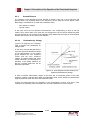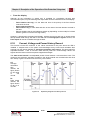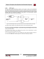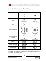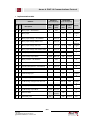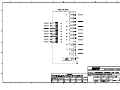
1
7IVD Distribution Protection and Control 7IVD-J/K/L MODELS © ZIV GRID AUTOMATION, S.L. 2012 Instructions Manual B7IV1206Jv00 License agreement for Software Embedded in Equipment ZIV APLICACIONES Y TECNOLOGÍA, S.L. End-User Software License Agreement THE EQUIPMENT YOU HAVE PURCHASED INCLUDES EMBEDDED SOFTWARE PROGRAM(S). THE PROGRAM IS COPYRIGHTED AND IS BEING LICENSED TO YOU (NOT SOLD) FOR USE WITH THE EQUIPMENT. THIS IS A LEGAL AGREEMENT BETWEEN US (AS “LICENSEE) AND ZIV APLICACIONES Y TECNOLOGIA, S.L. (AS “LICENSOR”) FOR THE SOFTWARE PROGRAM INCLUDED WITH THE EQUIPMENT. PLEASE READ THE TERMS AND CONDITIONS OF THIS LICENSE AGREEMENT CAREFULLY BEFORE USING THE EQUIPMENT. IF YOU INSTALL OR USE THE EQUIPMENT, YOU ARE ACCEPTING AND AGREEING TO THE TERMS OF THIS LICENSE AGREEMENT. IF YOU ARE NOT WILLING TO BE BOUND BY THE TERMS OF THIS LICENSE AGREEMENT, YOU SHOULD PROMPTLY RETURN THE EQUIPMENT UNUSED TO YOUR SELLER, AND YOU WILL RECEIVE A REFUND OF YOUR MONEY. Terms and Conditions of License 1. License Grant. Licensor hereby grants to you, and your accept, a nonexclusive and nontransferable license to use the embedded programs and the accompanying documentation, if any (collectively referred to as the “Software”), only as authorized in this License Agreement. 2. Restrictions. You may not (a) use, copy, modify or transfer the Software except as expressly provided in this or another Agreement with Licensor, (b) reverse engineer, decompile or disassemble or separate the components of the Software, or (c) rent, sell or lease the Software or make the Software available to others to do any of the foregoing. 3. No Assignment. This License is intended for your exclusive use with the purchased equipment. You agree that you will not assign, sublicense, transfer, pledge, lease, rent or share your rights under this License Agreement. 4. Licensor’s Rights. You acknowledge and agree that the Software is the proprietary product of Licensor protected under U.S. copyright law and international treaties.. You further acknowledge and agree that all right, title and interest in and to the Software, including associated intellectual property rights, are and shall remain with Licensor. This License Agreement does not convey to you an ownership interest in or to the Software, but only a limited right of use revocable in accordance with the terms of this License Agreement. 5. Confidentiality. The Software is confidential and no details or information relating to the same shall be disclosed to any third party without the prior written consent of Licensor. For the purposes of this clause, sub-contract staff, employed or retained by the Licensee to perform computer systems development work, shall not be deemed to be third parties provided such staff are subject to the disclosure restrictions set forth above. In no event, except with a prior written authorization duly signed by an officer of Licensor, may you disclose any such confidential information, even for subcontracted jobs, to persons or entities that may be considered to be direct competitors of Licensor. 6. Term. The License Agreement is effective upon delivery of the equipment to you and shall continue until terminated. You may terminate this License Agreement at any time by returning the equipment to Licensor, or by destroying the equipment. Licensor may terminate this License Agreement upon your breach of any term hereof. Upon such termination by Licensor, you agree to return the equipment to Licensor. 7. Warranty and Disclaimer. Licensor warrants, for your benefit only, that the Software, when and as delivered to you, will conform to the specifications described in the instruction manuals for the equipment purchased, or any specifications agreed to in writing by Licensor with a particular customer. This warranty does not cover any minor errors or deviations from the specifications that do not affect the proper functioning of the equipment. EXCEPT FOR THE WARRANTIES SET FORTH ABOVE, THE SOFTWARE IS LICENSED “AS IS”, AND LICENSOR DISCLAIMS ANY AND ALL OTHER WARRANTIES, WHETHER EXPRESS OR IMPLIED, INCLUDING, WITHOUT LIMITATION, ANY IMPLIED WARRANTIES OF MERCHANTABILITY OR FITNESS FOR A PARTICULAR PURPOSE. 8. Licensee’s Remedy. You sole and exclusive remedy for any breach of Licensor’s warranty shall be the repair or replacement, at Licensor’s sole option, of any Software that does not conform to stated specifications. Licensor shall not be responsible for any failure arising from inadequate or improper use of the Software. 9. Limitation of Liability. Licensor’s cumulative liability to you or any other party for any loss or damages resulting from any claims, demands, or actions arising out of or relating to this Agreement shall not exceed the purchase price paid to Licensor for the equipment. In no event shall Licensor be liable for any indirect, incidental, consequential, special, or exemplary damages or lost profits, even if licensor has been advised of the possibility of such damages. 10. Trademark. All ZIV trademarks (including ZIVERCOM, ZIVERLOG and ZIVERSYS) are common law trademarks of Licensor. No right, license or interest to such trademarks is granted hereunder, and you agree that no such right, license or interest shall be asserted by you with respect to such trademark. 11. Licensee’s Indemnity. You shall defend, indemnify and hold Licensor harmless against any loss or damage of any kind arising from a breach by you of this License Agreement, or any use or misuse of the Software by you or your employees, agents or representatives, and from any other of your conduct or from any claim or action by any of your customers in connection with the Software or this License Agreement. 12. Governing Law. This License Agreement shall be construed and governed in accordance with the internal laws of the State of Illinois, U.S.A. 13. No Waiver. The failure of either party to enforce any rights granted hereunder or to take action against the other party in the event of any breach hereunder shall not be deemed a waiver by that party as to subsequent enforcement of rights or subsequent actions in the event of future breaches. 14. Entire Agreement. This License Agreement is the entire agreement between you and Licensor with respect to the use of the software and supersedes all prior understandings or agreements between the parties. This License Agreement may be amended only by a writing signed by an officer of Licensor. ZIV Aplicaciones y Tecnología, S.L. Parque Tecnológico, 2089 48016 Zamudio (Vizcaya) 48080 Bilbao Spain Table of Contents Chapter 1. 1.1 1.2 1.2.1 1.2.2 1.3.2 1.3.3 1.3.4 1.3.5 1.3.6 1.3.7 1.3.8 1.4 1.5 Description General Overview ........................................................................................ Functions of the Protection Subsystem ....................................................... 3-Phase and Ground (3x50/51 + 50N/51N) Overcurrent Protection ........... 3-Phase and Ground (3x67+67N) Directional Overcurrent Protection (7IVD-L) ....................................................................................................... Minimum Voltage Protection (3x27) ............................................................ Maximum Voltage Protection (3x59) ........................................................... Frequency Units ........................................................................................... Breaker Failure Protection ........................................................................... Open Phase Unit ......................................................................................... Residual Current Detection Unit .................................................................. Three-Phase Recloser Function .................................................................. Maneuver Order Failure............................................................................... Functions of the Control Subsystem ............................................................ Local Bay Control with Indication of the Status and how to Maneuver on each of the Elements that Comprise it.................................................... Local Recloser Control ................................................................................ Local Control of the Ground Measurement Elements (Model 7IVD-L) ........ Changing the Active Group (Model 7IVD-L) ................................................ Display of the Measurements ...................................................................... Presentation of Local Alarms as Conventional Alarms ............................... Indication of the Status of the Digital Inputs and Outputs ........................... Indication of the Status of the Auxiliary Outputs and Protection LEDs ....... Additional Functions .................................................................................... Model Selection ........................................................................................... 1-5 1-5 1-5 1-5 1-6 1-6 1-6 1-6 1-6 1-9 Chapter 2. 2.1 2.2 2.2.1 2.2.2 2.2.3 2.2.4 2.2.5 2.2.6 2.2.7 2.2.8 2.2.9 2.2.10 2.3 2.3.1 2.3.2 2.3.3 2.3.4 2.3.5 2.3.6 2.3.7 Technical Data Power Supply Voltage ................................................................................. Protection Subsystem .................................................................................. Power Supply Burden .................................................................................. Current Analog Inputs .................................................................................. Voltage Analog Inputs.................................................................................. Measurement Accuracy ............................................................................... Time Measurement Accuracy ...................................................................... Repeatability ................................................................................................ Transient Overreach .................................................................................... Status Contact Inputs .................................................................................. Trip and Close Outputs ................................................................................ Auxiliary Contact Outputs ............................................................................ Control Subsystem ...................................................................................... Loads ........................................................................................................... Status Contact Inputs .................................................................................. Double Contact Outputs (SD1 and SD2) ..................................................... Single Contact Outputs ................................................................................ Converter Inputs / Outputs........................................................................... Measurement Accuracy (measurement board) ........................................... Time Measurement Accuracy ...................................................................... 2-2 2-2 2-2 2-2 2-2 2-3 2-3 2-3 2-3 2-4 2-4 2-5 2-5 2-5 2-5 2-6 2-6 2-6 2-7 2-7 1.2.3 1.2.4 1.2.5 1.2.6 1.2.7 1.2.8 1.2.9 1.2.10 1.3 1.3.1 I B7IV1206J 7IVD: Distribution Protection and Control © ZIV GRID AUTOMATION, S. L. Zamudio, 2012 1-2 1-3 1-3 1-3 1-4 1-4 1-4 1-4 1-4 1-4 1-4 1-5 1-5 Table of Contents 2.3.8 2.3.9 2.4 Current Input (measurement board) ............................................................ Voltage Input (measurement board) ............................................................ Communication Data ................................................................................... 2-7 2-7 2-8 Chapter 3. 3.1 3.2 3.3 3.4 3.5 Standards and Type Test Insulation ...................................................................................................... Electromagnetic Compatibility...................................................................... Environmental Test ...................................................................................... Power Supply ............................................................................................... Mechanical Test ........................................................................................... 3-2 3-2 3-3 3-3 3-3 Chapter 4. 4.1 4.2 4.3 4.4 4.4.1 4.4.2 Physical Architecture Modularity..................................................................................................... Protection and Control Interconnection ....................................................... Dimensions .................................................................................................. Connection Elements ................................................................................... Terminal blocks ............................................................................................ Removing printed circuit boards (non self-shorting) .................................... 4-2 4-4 4-4 4-4 4-4 4-4 Chapter 5. 5.1 5.1.1 5.1.2 5.1.3 5.1.4 5.1.5 5.1.6 5.1.7 5.1.8 5.1.9 5.2 5.2.1 5.2.2 5.2.3 5.2.4 5.2.5 Settings Protection Subsystem Settings .................................................................... Configuration Settings .................................................................................. General Settings .......................................................................................... Current Protection Settings .......................................................................... Voltage Elements Settings ........................................................................... Recloser Settings ......................................................................................... Logic Settings............................................................................................... Breaker Monitor Settings ............................................................................. History Log ................................................................................................... Oscillography Settings (optional) ................................................................. Control Subsystem Settings......................................................................... Configuration settings .................................................................................. General Settings .......................................................................................... Time Settings ............................................................................................... Logic Settings............................................................................................... Analog Settings ............................................................................................ 5-2 5-2 5-3 5-3 5-6 5-7 5-10 5-10 5-11 5-11 5-13 5-13 5-14 5-14 5-15 5-15 Chapter 6. 6.1 6.1.1 6.1.1.a 6.1.2 6.1.3 6.1.4 6.1.5 6.2 6.2.1 6.2.1.a 6.2.2 6.2.2.a 6.2.2.b 6.2.2.c 6.2.3 6.2.4 6.3 6.4 Description of the Operation of the Protection Subsystem Overcurrent Elements .................................................................................. Time Overcurrent ......................................................................................... Current / Time Curve: Inverse Functions ..................................................... Instantaneous Overcurrent .......................................................................... Block diagrams of the Overcurrent Elements .............................................. Torque Control (Pickup Lockout Enable) ..................................................... Block Trip and Bypass Time ........................................................................ Directional Element (Model 7IVD-L) ............................................................ Phase Elements ........................................................................................... Example ....................................................................................................... Ground Element ........................................................................................... Polarization by voltage ................................................................................. Polarization by current ................................................................................. Polarization by Voltage and Current ............................................................ Blocking Due to Lack of Polarization ........................................................... Inversion of the Trip Direction ...................................................................... Undervoltage Elements................................................................................ Overvoltage Elements.................................................................................. 6-3 6-3 6-4 6-9 6-9 6-10 6-11 6-12 6-13 6-14 6-15 6-15 6-16 6-16 6-16 6-16 6-17 6-18 II B7IV1206J 7IVD: Distribution Protection and Control © ZIV GRID AUTOMATION, S. L. Zamudio, 2012 Table of Contents 6.5 6.6 6.7 6.8 6.9 6.10 6.11 6.11.1 6.11.2 6.11.3 6.11.4 6.11.5 6.11.6 6.11.7 6.11.8 6.12 6.12.1 6.12.2 6.12.3 6.12.3.a 6.13 6.13.1 6.13.2 6.13.3 6.13.4 6.14 6.14.1 6.15 6.16 6.17 6.18 6.18.1 6.19 6.20 6.20.1 6.20.2 6.20.3 6.21 6.21.1 6.21.2 6.21.3 6.22 Frequency Elements .................................................................................... Breaker Failure Function ............................................................................. Open Phase Element................................................................................... Residual Current Detection Element ........................................................... General Settings .......................................................................................... Configuration Settings (7IVD-L model) ........................................................ Recloser ....................................................................................................... Reclose Sequence....................................................................................... Recloser Lockout ......................................................................................... Manual Close ............................................................................................... Manual and External Blocking ..................................................................... Definitive Trip ............................................................................................... Recloser Not in Service ............................................................................... Reclose Attempts Counter ........................................................................... Recloser Control Masks............................................................................... Logic ............................................................................................................ Trip Output Seal-in Enable .......................................................................... Breaker Open and Close Failure Timer ....................................................... Close through the Recloser Function .......................................................... Coordination Time (Model 7IVD-L) .............................................................. Trip and Close Coil Circuit Supervision ....................................................... Open Circuit ................................................................................................. Close Circuit ................................................................................................ Selection of the Operation Mode of the Digital Status Contact Inputs ........ Trip/Close Output Supervision ..................................................................... Breaker Monitoring ...................................................................................... Excessive Number of Trips .......................................................................... Setting Group Control .................................................................................. Event Record ............................................................................................... Fault Reports ............................................................................................... Current, Voltage and Power History Record ............................................... Recording of maximums and minimums and history of measurements (load profile, model 7IVD-L) ......................................................................... Oscillographic Register (Optional) ............................................................... Contact Inputs, Outputs and LED Targets................................................... Contact Inputs .............................................................................................. Auxiliary Contact and Trip Outputs .............................................................. LED targets .................................................................................................. Communications .......................................................................................... Communications Settings ............................................................................ Communications Types ............................................................................... Communicating with the 7IVD ..................................................................... Alarm Codes ................................................................................................ Chapter 7. 7.1 7.2 7.2.1 7.2.2 7.2.2.a 7.2.2.b 7.2.2.c 7.2.2.d 7.2.3 7.2.3.a 7.2.3.b Description of the Operation of the Control Subsystem Operational Characteristics ......................................................................... Control Subsystem ...................................................................................... Elements of the Control Subsystem ............................................................ Control Unit Input Data ................................................................................ Communication Inputs ................................................................................. Protection Subsystem Inputs ....................................................................... Physical Inputs ............................................................................................. Inputs via the Human-Machine Interface (Control HMI) .............................. Data Output from the Control Subsystem.................................................... Communication Outputs .............................................................................. Signals Sent to the Protection Subsystem .................................................. III B7IV1206J 7IVD: Distribution Protection and Control © ZIV GRID AUTOMATION, S. L. Zamudio, 2012 6-18 6-19 6-20 6-21 6-22 6-23 6-25 6-25 6-29 6-29 6-30 6-31 6-31 6-31 6-32 6-34 6-34 6-34 6-34 6-34 6-35 6-35 6-36 6-37 6-37 6-38 6-38 6-39 6-40 6-47 6-48 6-49 6-50 6-52 6-52 6-55 6-66 6-67 6-67 6-67 6-67 6-68 7-2 7-3 7-6 7-7 7-7 7-8 7-8 7-8 7-9 7-9 7-9 Table of Contents 7.2.3.c 7.2.3.d Physical Outputs .......................................................................................... Outputs to the Human-Machine Interface (HMI Control Subsystem) .......... 7-9 7-10 Chapter 8. 8.1 8.2 8.3 8.3.1 8.4 8.5 Alphanumeric Keypad and Display Alphanumeric Keypad and Display .............................................................. Keys, Functions and Operation Modes ........................................................ Accessing the Protection Functions with a Single Key (F2) ........................ Last trip indication ........................................................................................ Function Access Using the Keypad ............................................................. Control Function Access .............................................................................. 8-2 8-3 8-6 8-6 8-10 8-19 Chapter 9. 9.1 9.2 9.3 9.3.1 9.3.2 9.3.3 9.3.4 9.4 9.4.1 9.4.2 9.4.3 9.4.4 9.4.5 Local Control Display Graphic General ........................................................................................................ Symbols Used in the Graphic Display ......................................................... Accessing the Information............................................................................ Alarms Information ....................................................................................... Digital Input / Output Indication Information................................................. Measurement Information ............................................................................ Date and Time Information .......................................................................... How the Control Functions Work ................................................................. General Procedure for Executing Maneuvers.............................................. Procedure for opening / closing breakers and disconnecting switches ....... Breaker Tagging Procedure ......................................................................... Control Procedure for other Logical Devices ............................................... Procedure for Managing Alarms .................................................................. 9-2 9-3 9-6 9-7 9-8 9-8 9-9 9-10 9-10 9-11 9-12 9-13 9-13 Chapter 10. Receiving Test 10.1 General ........................................................................................................ 10.1.1 Accuracy ...................................................................................................... 10.2 Preliminary inspection .................................................................................. 10.3 Insulation test ............................................................................................... 10.4 Verification of the Power Supply .................................................................. 10.5 Protection Subsystem Receiving Tests ....................................................... 10.5.1 Measurement Tests ..................................................................................... 10.5.2 Test of the Phase and Ground Current Elements........................................ 10.5.3 Directional Element Test (Model 7IVD-L) .................................................... 10.5.4 Voltage Element Test................................................................................... 10.5.4.a Overvoltage Element Test ........................................................................... 10.5.4.b Undervoltage Unit Test ................................................................................ 10.5.5 Frequency Elements Test ............................................................................ 10.5.6 Open Phase Element Test ........................................................................... 10.5.7 Residual Current Unit Test........................................................................... 10.5.8 Breaker Failure Detection Test .................................................................... 10.5.9 Recloser Test ............................................................................................... 10.5.10 Trip / close Coil Circuit Supervision Input Test ............................................ 10.6 Control Subsystem Receiving Tests ............................................................ 10.6.1 Test Configuration ........................................................................................ 10.6.2 Status Contact Inputs Test.......................................................................... 10.6.3 Auxiliary Contact Outputs and LED Targets Test ...................................... 10.6.4 Metering Test ............................................................................................... 10.7 Communications Test .................................................................................. 10.8 Installation .................................................................................................... 10.8.1 Location........................................................................................................ 10.8.2 Connection ................................................................................................... 10-2 10-3 10-3 10-3 10-4 10-4 10-4 10-5 10-6 10-7 10-7 10-7 10-8 10-10 10-10 10-10 10-11 10-11 10-12 10-12 10-13 10-14 10-14 10-15 10-16 10-16 10-16 IV B7IV1206J 7IVD: Distribution Protection and Control © ZIV GRID AUTOMATION, S. L. Zamudio, 2012 Table of Contents A. A.1 A.2 A.3 A.3.1 A.3.2 A.3.2.a A.4 A.4.1 A.4.2 DNP 3.0 Communications Protocol Physical Architecture ................................................................................... Settings ........................................................................................................ Description of Operation .............................................................................. DNP 3.0 Protocol ......................................................................................... Communications .......................................................................................... Communicating with the 7IVD ..................................................................... Alphanumeric Keyboard and Display .......................................................... Change Settings .......................................................................................... DNP3.0 Protocol .......................................................................................... A-2 A-2 A-3 A-3 A-8 A-8 A-8 A-8 A-8 B. B.1 B.1.1 B.2 B.2.1 B.2.2 B.2.2.a B.2.2.b B.3 B.3.1 B.3.2 B.3.2.a B.3.2.b B.4 B.4.1 B.4.1.a B.4.2 B.5 B.5.1 B.5.2 B.5.3 B.5.3.a B.5.4 B.5.4.a Models with a Fault Locator Settings ........................................................................................................ Locator Settings ........................................................................................... Description of Operation .............................................................................. Fault Report ................................................................................................. Fault Locator (Operation)............................................................................. Fault Locator (Setting) ................................................................................. Location Information .................................................................................... Description of Operation of the Control Subsystem .................................... Functional Characteristics ........................................................................... Control Unit .................................................................................................. Inputting Data to the Control Subsystem ..................................................... Outputting Data from the Control Subsystem .............................................. Alphanumeric Keyboard and Display .......................................................... Using the F2 Key to Access the Functions .................................................. Last trip Indication and Recloser State ........................................................ Locator Settings ........................................................................................... Local Control Graphic Display ..................................................................... General ........................................................................................................ Symbols Used in the Graphic Display ......................................................... Accessing the Information ........................................................................... Measurement Information ............................................................................ Operation of the Control Functions.............................................................. Control Procedure for other Logic Devices.................................................. B-2 B-2 B-2 B-2 B-3 B-4 B-6 B-7 B-7 B-7 B-7 B-7 B-7 B-7 B-7 B-8 B-10 B-10 B-10 B-10 B-10 B-10 B-10 C. Schemes and Drawings D. D.1 D.2 List of Illustrations and Tables List of Figures .............................................................................................. List of Tables ............................................................................................... E. Warranty V B7IV1206J 7IVD: Distribution Protection and Control © ZIV GRID AUTOMATION, S. L. Zamudio, 2012 D-2 D-3 Table of Contents VI B7IV1206J 7IVD: Distribution Protection and Control © ZIV GRID AUTOMATION, S. L. Zamudio, 2012 1. Description 1.1 General Overview ....................................................................................................... 1-2 1.2 Functions of the Protection Subsystem ...................................................................... 1-3 1.2.1 3-Phase and Ground (3x50/51 + 50N/51N) Overcurrent Protection .......................... 1-3 1.2.2 3-Phase and Ground (3x67+67N) Directional Overcurrent Protection (7IVD-L) ...................................................................................................................... 1-3 1.2.3 Minimum Voltage Protection (3x27)............................................................................ 1-4 1.2.4 Maximum Voltage Protection (3x59)........................................................................... 1-4 1.2.5 Frequency Units .......................................................................................................... 1-4 1.2.6 Breaker Failure Protection .......................................................................................... 1-4 1.2.7 Open Phase Unit......................................................................................................... 1-4 1.2.8 Residual Current Detection Unit ................................................................................. 1-4 1.2.9 Three-Phase Recloser Function ................................................................................. 1-4 1.2.10 1.3 1.3.1 Maneuver Order Failure .............................................................................................. 1-5 Functions of the Control Subsystem ........................................................................... 1-5 Local Bay Control with Indication of the Status and how to Maneuver on each of the Elements that Comprise it ................................................................... 1-5 1.3.2 Local Recloser Control ............................................................................................... 1-5 1.3.3 Local Control of the Ground Measurement Elements (Model 7IVD-L) ....................... 1-5 1.3.4 Changing the Active Group (Model 7IVD-L) ............................................................... 1-5 1.3.5 Display of the Measurements ..................................................................................... 1-6 1.3.6 Presentation of Local Alarms as Conventional Alarms............................................... 1-6 1.3.7 Indication of the Status of the Digital Inputs and Outputs........................................... 1-6 1.3.8 Indication of the Status of the Auxiliary Outputs and Protection LEDs....................... 1-6 1.4 Additional Functions.................................................................................................... 1-6 1.5 Model Selection .......................................................................................................... 1-9 Chapter 1. Description The 7IVD series is a family of IEDs for feeder or machine protection and control applications. This family is based on digital technology and adapts to all requirements imposed by the various possible configurations of MV electric IEDs in substations. This family of equipment features the following functions: complete protection of a given bay; monitoring and annunciation (remote and optionally local) of all the devices associated to that bay: breaker, disconnecting switches, etc. with their corresponding interlockings; analog values metering (current, voltage, power...); capture of the field information associated with the bay through digital status contact inputs; possibility of setting up programmable control functions and local interlockings; 7IVD systems are designed for medium voltage lines, transformers, generators and feeders in general where a protection, control and measurement device is required. This Instruction Manual refers to models 7IVD-J, 7IVD-K and 7IVD-L and specifies the corresponding characteristics in each case. 1.1 General Overview 7IVD IEDs are made up of two subsystems, the protection subsystem and the control subsystem. Consequently they perform protection and control functions. Both subsystems intercommunicate so that they can cooperate by information exchange, but always maintaining separate identities for any kind of action. The major features are: • The IEDs have independent power supplies and microprocessors for protection and control. • The communication ports available are common for both subsystems: protection and control. • The auxiliary contact outputs as well as the digital status contact inputs are independent for protection and control. • The protection measures analog inputs by means of circuits that are independent from the control circuits. Optionally, you can implement a measurement board exclusively dedicated to this function. 1-2 B7IV1206J 7IVD: Distribution Protection and Control © ZIV GRID AUTOMATION, S. L. Zamudio, 2012 Chapter 1. Description 1.2 Functions of the Protection Subsystem 1.2.1 3-Phase and Ground (3x50/51 + 50N/51N) Overcurrent Protection All the models have four overcurrent measuring elements (three phase and one ground element). In models 7IVD-K and 7IVD-L, each IED contains a time element and an instantaneous element with an additional adjustable timer. Each 7IVD-J model IED is comprised of a time element and two instantaneous elements with an additional adjustable timer. The time elements have five selectable time-current curves: inverse, very inverse, extremely inverse, definite time and a user-defined curve. The 7IVD-L model has another two timecurrent curves: long time-inverse and short time-inverse. There are settings for enabling or disabling the time and instantaneous elements for phases and ground. These phase and ground elements have three selectable setting groups (one active and two in reserve). These models have independent LED targets for the pickup of the phase and ground time elements as well as independent LED targets for instantaneous and delayed trip that can be directed to the auxiliary outputs. 1.2.2 3-Phase and Ground (3x67+67N) Directional Overcurrent Protection (7IVD-L) Model 7IVD-L has four additional directional overcurrent measuring elements (three phase and one ground). Each unit contains a time element and an instantaneous element with an additional adjustable timer. The time elements have seven selectable time-current curves: inverse, very inverse, extremely inverse, short time-inverse, long time-inverse, fixed time and one user-defined curve. There are settings for enabling or disabling the time and instantaneous elements for phases and ground. These phase and ground elements have three selectable setting groups (one active and two in reserve). These models have independent LED targets for the pickup of the phase and ground time elements as well as independent LED targets for instantaneous and delayed trip. 1-3 B7IV1206J 7IVD: Distribution Protection and Control © ZIV GRID AUTOMATION, S. L. Zamudio, 2012 Chapter 1. Description 1.2.3 Minimum Voltage Protection (3x27) They have three undervoltage units; each of them has an instantaneous (common setting) element with an additional adjustable timer. The undervoltage units are activated or deactivated together. 1.2.4 Maximum Voltage Protection (3x59) They have three overvoltage units; each of them has an instantaneous (common setting) element with an additional adjustable timer. The overvoltage units are activated or deactivated together. 1.2.5 Frequency Units They have two frequency units associated with an analog voltage input. Each of them can function as an overfrequency or underfrequency unit with independent timing. Both elements are activated or deactivated together. 1.2.6 Breaker Failure Protection The IED has a built-in (three-phase trip) breaker failure function, which sends trip commands to one or more other breakers. 1.2.7 Open Phase Unit The function of this unit is to detect the opening of any of the phases and, if detected, to make the trip and eliminate unbalance. 1.2.8 Residual Current Detection Unit The purpose of the residual current detection unit is to generate a trip as soon as it detects the circulation of zero sequence current (that does not reach the fault level) in a pre-set time interval. The circulation of this current indicates that there is an unbalance of currents in the installation. 1.2.9 Three-Phase Recloser Function The recloser function offers the possibility of coordinating with an external protection device in addition to the IED's built-in protection. Reclosing sequences for phase and ground faults can be set independently. Reclosing is selectable up to a maximum of four attempts with independent settings for recloser timers and reset times. The breaker position controls the reclosing sequence with the reclose initiate signal. The trip elements and reclose attempts enabled during a fault clearing and reclosing sequence are selectable. Manual closing can be initiated from the IED using its reclosing output contacts. The close command in this instance is supervised and controlled in the same way as any permissible automatic reclosing command following a trip from the protection elements. 1-4 B7IV1206J 7IVD: Distribution Protection and Control © ZIV GRID AUTOMATION, S. L. Zamudio, 2012 Chapter 1. Description 1.2.10 Maneuver Order Failure The proper reception of the status change of the breaker is verified after each maneuver. 1.3 Functions of the Control Subsystem Since the control subsystem is configurable, in general, it can have the following functions: 1.3.1 Local Bay Control with Indication of the Status and how to Maneuver on each of the Elements that Comprise it By means of the keypad, you can act on each of the elements that comprise the bay. A preprogrammed logic governs these operations and always takes into account the signals that arrive from the protection subsystem and the equipment's status (local or remote control). 1.3.2 Local Recloser Control You can enable or disable the recloser from the keypad or via communications. Before this command is executed, the logic decides whether or not it is feasible. If the order is not executed, a message appears and, if it is executed, the recloser symbol will change to the new status. 1.3.3 Local Control of the Ground Measurement Elements (Model 7IVD-L) You can block or unblock the trip signaling of the ground measuring elements together from the keypad. Before this command is executed, the logic decides whether or not it is feasible. The symbol that represents the elements will indicate the new status. 1.3.4 Changing the Active Group (Model 7IVD-L) You can change the active group from the keypad or via communications. Before this command is executed, the logic decides whether or not it is feasible. If the order is not executed, a message appears and, if it is executed, the enabling symbol will indicate the new status. 1-5 B7IV1206J 7IVD: Distribution Protection and Control © ZIV GRID AUTOMATION, S. L. Zamudio, 2012 Chapter 1. Description 1.3.5 Display of the Measurements The graphic display presents the measurements (currents, voltages, powers...) that the control subsystem receives through the protection subsystem or from the measurement board. 1.3.6 Presentation of Local Alarms as Conventional Alarms The graphic display can also present the information related to alarm signals. One of the screens displays the alarms processed in the logic, those that come from the protection subsystem and those that are directly obtained from analog input signals. 1.3.7 Indication of the Status of the Digital Inputs and Outputs You can view all the control digital inputs and outputs on the screens of the graphic display. 1.3.8 Indication of the Status of the Auxiliary Outputs and Protection LEDs You can view the status of all the auxiliary outputs and protection LEDs on the screens of the graphic display. 1.4 • Additional Functions Selecting the phase sequence (model 7IVD-L) The protection subsystem of the IEDs allows you to configure the measurement of the phase currents according to a sequence: ABC or CBA. • Trip and close circuit monitoring The IED's protection subsystem has elements to monitor the proper operation of the breaker's trip and close circuits. Both circuits are monitored in both breaker statuses (open and closed). The monitoring generates two digital outputs: trip circuit failure and close circuit failure. • Monitoring the switching outputs Associated with the functions of monitoring the trip and close circuits, the protection subsystem has functions that monitor the switching outputs (closure and trip). • Breaker maintenance monitoring To have information for maintaining the breaker, the IED's protection subsystem has an element that sums and accumulates the kA2 values each time it trips. • Excessive number of trips This function, available in the protection subsystem, prevents the breaker from making an undesirable number of maneuvers in a given period of time that, as a result, possibly damaging the breaker. 1-6 B7IV1206J 7IVD: Distribution Protection and Control © ZIV GRID AUTOMATION, S. L. Zamudio, 2012 Chapter 1. Description • LED targets There are fourteen LEDs. Twelve of them are user-definable and the other two indicate the availability of the protection and control subsystems respectively. Of the twelve definable LEDs, four correspond to the protection subsystem and eight to the control subsystem. • Measurement board (optional) By using the measurement board, you have three analog current inputs and three analog voltage inputs and, therefore, the possibility of measuring currents, voltages, powers, energies, etc. • Protection and control digital status contact inputs The protection and control subsystems have a number of digital status contact inputs, depending on the model. Their function is determined by the settings programmed in the IED. • Protection and control auxiliary outputs The number of auxiliary outputs available depends on the 7IVD model. The function of these auxiliary outputs is determined by the settings programmed in the IED. • Oscillography settings (optional) The oscillography settings serve two different functions: retrieval and display. In the 7IVD-L model, it retrieves the analog magnitudes as well as the digital signals. 1-7 B7IV1206J 7IVD: Distribution Protection and Control © ZIV GRID AUTOMATION, S. L. Zamudio, 2012 Chapter 1. Description • Local information (alphanumeric display, keypad and graphic display) Use the push-buttons next to the graphic display or the keypad located next to the alphanumeric display to obtain information about the monitored bay. Alphanumeric display: - Modification and visualization of protection and control settings - Protection operations: Elements picked up. Elements energized. Contact input and output status. - Protection event recording (if the model has the oscillographic register function defined, these logs can only be viewed through communications): Sequence of events recording. Current log file (the 7IVD-L model also saves the voltages, powers, power factor and energies). - Measurements used by the protection subsystem. Phase and ground currents (and their angles in model 7IVD-L). Currents of the three phases (and their angles in model 7IVD-L). Phase-to-phase voltages (only for model 7IVD-L). Maximum current (maximums and minimums in model 7IVD-L). Maximum voltage (maximums and minimums in model 7IVD-L) Positive and negative sequence currents (and zero sequence only for model 7IVD-L) Active and reactive powers (apparent power only in model 7IVD-L) and power factor Maximum and minimum powers (model 7IVD-L) Frequency Energies (model 7IVD-L) Graphic display: - Single-wire bay presentation - Alarm panel - Contact input and output status - Measurements and counters • Self-test program A continuously running diagnostic self-test program verifies the correct operation of all the components. 1-8 B7IV1206J 7IVD: Distribution Protection and Control © ZIV GRID AUTOMATION, S. L. Zamudio, 2012 Chapter 1. Description 1.5 Model Selection K 7IVD 1 1 2 4 5 6 7/8/9 3 4 5 Functions J 3 x (2x 50)/51 + 2x50N/51N + 3 x 27 + 3 x 59 + 81 + 79 K 3 x 50/51 + 50N/51N + 3 x 27 + 3 x 59 + 81 + 79 Options 0 1 3 2 Special Model Basic Model Nominal Current E 1A F 5 A + Optional Ground Status Power Supply Contacs Inputs 1 24-48 Vdc (±20%) 24-48 Vdc 2 110-125 Vdc (±20%) 24-125 Vdc 6 10 L 3 x 50/51 + 50N/51N + 3 x 67 + 67N + 3 x 27 + 3 x 59 + 81 + 79 2 8 Oscillographic register Osc. Reg. with digital TOPS + Locator G N 5 A (Phase) + 1 A (Ground) 5A Status Power Supply Contacs Inputs 220-250 Vdc (±20%) 48-250 Vdc 90-250 Vdc/ac (±20%) 24-125 Vdc Monitoring Inputs 24-48 Vdc 125 Vdc 7/8/9 3 6 Monitoring Inputs 250 Vdc 125 Vdc Rated Voltage / Frequency / Language 1 110 and 110 √3 Vac / 50 Hz / Spanish D 120 and 120 √3 Vac / 60 Hz / Spanish 3 120 and 120 √3 Vac / 60 Hz / English F 120 and 120 √3 Vac / 60 Hz / Portuguese B 110 and 110 √3 Vac / 50 Hz / English 5 6 A RS232 + RS485 RS232 + Plastic F.O. (double ring) RS232 + Glass F.O. ST double rear port Communications 1 RS232 + RS232 2 RS232 + Plastic F.O. (1mm) 4 RS232 + Glass F.O. (with ST) Inputs / Outputs / Measurement Module To be defined at factory 10 Enclosure K 4 U x 1 19" rack 11 Communications Protocol To be defined at factory 1-9 B7IV1206J 7IVD: Distribution Protection and Control © ZIV GRID AUTOMATION, S. L. Zamudio, 2012 11 Chapter 1. Description • Functions 50 51 50N 51N 67 67N 27 59 81 79 Phase Instantaneous Overcurrent. Phase Time Overcurrent (inverse / definite). Ground Instantaneous Overcurrent. Ground Time Overcurrent (inverse / definite). Phase Directional. Ground Directional. Phase Undervoltage. Phase Overvoltage. Frequency Protection. Recloser. 1-10 B7IV1206J 7IVD: Distribution Protection and Control © ZIV GRID AUTOMATION, S. L. Zamudio, 2012 2. Technical Data 2.1 Power Supply Voltage ................................................................................................ 2-2 2.2 Protection Subsystem ................................................................................................. 2-2 2.2.1 Power Supply Burden ................................................................................................. 2-2 2.2.2 Current Analog Inputs ................................................................................................. 2-2 2.2.3 Voltage Analog Inputs ................................................................................................. 2-2 2.2.4 Measurement Accuracy .............................................................................................. 2-3 2.2.5 Time Measurement Accuracy ..................................................................................... 2-3 2.2.6 Repeatability ............................................................................................................... 2-3 2.2.7 Transient Overreach ................................................................................................... 2-3 2.2.8 Status Contact Inputs ................................................................................................. 2-4 2.2.9 Trip and Close Outputs ............................................................................................... 2-4 2.2.10 Auxiliary Contact Outputs ........................................................................................... 2-5 2.3 Control Subsystem...................................................................................................... 2-5 2.3.1 Loads .......................................................................................................................... 2-5 2.3.2 Status Contact Inputs ................................................................................................. 2-5 2.3.3 Double Contact Outputs (SD1 and SD2) .................................................................... 2-6 2.3.4 Single Contact Outputs ............................................................................................... 2-6 2.3.5 Converter Inputs / Outputs .......................................................................................... 2-6 2.3.6 Measurement Accuracy (measurement board) .......................................................... 2-7 2.3.7 Time Measurement Accuracy ..................................................................................... 2-7 2.3.8 Current Input (measurement board) ........................................................................... 2-7 2.3.9 Voltage Input (measurement board) ........................................................................... 2-7 2.4 Communication Data .................................................................................................. 2-8 Chapter 2. Technical Data 2.1 Power Supply Voltage 7IVD power supplies are independent of auxiliary supply (one for each of the two subsystems and for the measuring board) and their values can be selected depending on the specific model: 24-48 Vdc (±20%) 110-125 Vdc (±20%) 220-250 Vdc (±20%) 90 - 250Vdc and 90 - 220Vac (-10% / +20%) Note: In case of power supply failure, a maximum interruption of 100 ms is allowed for 110 Vdc input. 2.2 Protection Subsystem 2.2.1 Power Supply Burden Quiescent Maximum 2.2.2 7W 20 W Current Analog Inputs Rated value In = 5A or 1A (depending on the model) 4 In (continuously) 50 In (during 3 s) 100 In (during 1 s) 240 In In = 5 A <0.2 VA In = 1 A <0.05 VA Thermal withstand capability Dynamic limit Current circuit burden 2.2.3 Voltage Analog Inputs Rated value Thermal withstand capability Voltage circuit burden Vn = 110 V (50 Hz) or 120 V (60Hz) 2 Vn (continuously) Vn = 110 V < 0.5 VA 2-2 B7IV1206J 7IVD: Distribution Protection and Control © ZIV GRID AUTOMATION, S. L. Zamudio, 2012 Chapter 2. Technical Data 2.2.4 Measurement Accuracy Current < 5 % or 20 mA (whichever is greater) for In = 1A or 5A <5% < 0.005 Hz Voltage Frequency 2.2.5 Time Measurement Accuracy Definite and inverse time curve E = 5% or 25 ms (whichever is greater) (UNE 21-136 and IEC 255) 2.2.6 Repeatability Operating time 2.2.7 2 % or 25 ms (whichever is greater) Transient Overreach Expressed as: ST = I −I I A T x100 A <10% for totally inductive lines <5% for lines with an impedance angle of 70º or less IA = Pick up value for a current with no dc component IT = Pick up value for a current with maximum dc offset 2-3 B7IV1206J 7IVD: Distribution Protection and Control © ZIV GRID AUTOMATION, S. L. Zamudio, 2012 Chapter 2. Technical Data 2.2.8 Status Contact Inputs Separate and configurable inputs with polarity. Status contact input voltage range Input IN1 Inputs IN2 to IN8 (selectable range depending on the model) 110 Vac ±20 % or 125 Vdc 20% 24 - 125 Vdc ±20 % 48 - 250 Vdc ±20 % Inputs IN5 to IN8 will be fed to a selectable voltage (depending on the model) when their application is to monitor the trip and/or close circuits. Ranges available 24 - 48 Vdc ±20% 125 Vdc ±20% 250 Vdc ±20% < 5 mA Current drain 2.2.9 Trip and Close Outputs 2 contacts generally open, one of them internally definable to closed. Make and carry (with resistive load) Continuous (with resistive load) Connection capability Breaking capability: (with resistive load) 30 A during 1 s 8A 2500 W 150 W - max. 8 A - (up to 48 Vdc) 55 W (80 Vdc - 250 Vcc) 1250 VA 60 W to 125 Vdc 250 Vdc Breaking capability (L/R = 0.04 s) Switching voltage Momentary close time trip contacts remain closed 100 ms 2-4 B7IV1206J 7IVD: Distribution Protection and Control © ZIV GRID AUTOMATION, S. L. Zamudio, 2012 Chapter 2. Technical Data 2.2.10 Auxiliary Contact Outputs Switched contacts open and closed and contacts generally open Make and carry (with resistive load) Continuous (with resistive load) Connection capability Break (resistive) 5 A for 30 s 3A 2000 W 75 W - (max. 3 A) up to (48 Vdc) 40 W (80 Vdc - 250 Vdc) 1000 VA 20 W up to 125 Vdc 250 Vdc Break (L/R = 0.04 s) Switching voltage 2.3 Control Subsystem 2.3.1 Loads Power Supply Burden Quiescent Maximum 9W 20 W Measurement Board Loads Quiescent Maximum 4W 9W 2.3.2 Status Contact Inputs The number of digital status contact inputs depends on the model. Rated voltage for status contact inputs 24-125 Vdc ±20% 48-250 Vdc ±20% Current drain < 5 mA 2-5 B7IV1206J 7IVD: Distribution Protection and Control © ZIV GRID AUTOMATION, S. L. Zamudio, 2012 Chapter 2. Technical Data 2.3.3 Double Contact Outputs (SD1 and SD2) Make and carry (with resistive load) Continuous (with resistive load) Close: Breaking capability (with resistive load) 30 A during 1 s 8A 2500 W 150 W -max. 8 A- (up to 48 Vdc) 55 W (80 Vdc - 250 Vdc) 1250 VA 60 W to 125 Vdc 250 Vdc Break (L/R = 0.04 s) Switching voltage Momentary close time: trip contacts remain open 2.3.4 100 ms Single Contact Outputs Make and carry (with resistive load) Continuous (with resistive load) Close Break (resistive) 5 A for 30 s 3A 2000 W 75 W -max. 3A- (up to 48 Vdc) 40 W (80 - 250 Vdc) 1000 VA 20 W to 125 Vdc 250 Vdc Break (L/R = 0.04 s) Switching voltage 2.3.5 Converter Inputs / Outputs Input impedance Load impedance < 1kΩ < 1kΩ 2-6 B7IV1206J 7IVD: Distribution Protection and Control © ZIV GRID AUTOMATION, S. L. Zamudio, 2012 Chapter 2. Technical Data 2.3.6 Measurement Accuracy (measurement board) Measurement Accuracy 2.3.7 < 0.5% Time Measurement Accuracy Time Measurement Accuracy 2.3.8 E = 5% or 30 ms (whichever is greater) Current Input (measurement board) Rated value Phase and ground elements Thermal withstand capability In=5 A or 1 A 4 In (continuously) 50 In (for 3 s) 100 In (for 1 s) 240 In In=5A < 0.2 W Dynamic limit Voltage circuit burden 2.3.9 Voltage Input (measurement board) Rated value Thermal withstand capability Voltage circuit burden Depending on the model 2 In (continuously) In = 110 V < 0.5 VA 2-7 B7IV1206J 7IVD: Distribution Protection and Control © ZIV GRID AUTOMATION, S. L. Zamudio, 2012 Chapter 2. Technical Data 2.4 Communication Data Glass Fiber Optics Type Wavelength Connector Transmitter minimum power 50/125 fiber 62.5/125 fiber 100/140 fiber Receiver sensitivity Multimode 820 nm ST - 20 dBm -17 dBm -7 dBm -25.4 dBm Plastic Fiber Optics (1 mm) Wavelength Transmitter minimum power Receiver sensitivity 660 nm -16 dBm -39 dBm RS232C Port Signals Front dB-9 connector, signals used Pin 2 - RXD Pin 3 - TXD Pin 5 - GND Pin 6 - DSR dB-25 connector, signals used Pin 2 - TXD Pin 3 - RXD Pin 4 - RTS Pin 5 - CTS Pin 7 - GND RS485C Port Signals Signals used A (B5) B (B6) 2-8 B7IV1206J 7IVD: Distribution Protection and Control © ZIV GRID AUTOMATION, S. L. Zamudio, 2012 3. Standards and Type Test 3.1 Insulation ..................................................................................................................... 3-2 3.2 Electromagnetic Compatibility .................................................................................... 3-2 3.3 Environmental Test ..................................................................................................... 3-3 3.4 Power Supply .............................................................................................................. 3-3 3.5 Mechanical Test .......................................................................................................... 3-3 Chapter 3. Standards and Type Tests The equipment satisfies the requirements of IEC-255 (EN 21-136) at the maximum class for the values indicated below. 3.1 Insulation Insulation Test (Dielectric Strength) Between all circuit terminals and ground Between all circuit terminals IEC-60255-5 2 kV, 50 Hz, for 1 min 2 kV, 50 Hz, for 1min Voltage Impulse Test IEC-60255-5 5 kV; 1.2/50 μs; 0.5 J 3.2 Electromagnetic Compatibility 1 MHz Burst Test Common mode Differential mode IEC-60255-22-1 Class III 2.5kV 1.0kV Fast Transient Disturbance Test IEC-60255-22-4 Class IV (IEC 61000-4-4) 4 kV ±10 % Radiated Electromagnetic Field Disturbance Amplitude modulated Pulse modulated IEC 61000-4-3 Class III 10 V/m 10 V/m Conducted Electromagnetic Field Disturbance Amplitude modulated IEC 61000-4-6 Class III 10 V Electrostatic Discharge IEC 60255-22-2 Class IV (IEC 61000-4-2) ±8 kV ±10 % On contacts Radio Frequency Emissivity EN55022 (Radiated) EN55011 (Conducted) 3-2 B7IV1206J 7IVD: Distribution Protection and Control © ZIV GRID AUTOMATION, S. L. Zamudio, 2012 Chapter 3. Standards and Type Tests 3.3 Environmental Test Temperature Operating range Storage range Humidity 3.4 IEC 60255-6 From -10º C to + 55º C From -25º C to + 70º C 95 % (non-condensing) Power Supply Power Supply Interference and Ripple 3.5 IEC 60255-11 < 20 % Mechanical Test Vibration (sinusoidal) Mechanical Shock and Bump Test IEC-60255-21-1 Class I IEC-60255-21-2 Class I The models comply with the IEC 89/336 standard of electromagnetic compatibility. 3-3 B7IV1206J 7IVD: Distribution Protection and Control © ZIV GRID AUTOMATION, S. L. Zamudio, 2012 Chapter 3. Standards and Type Tests 3-4 B7IV1206J 7IVD: Distribution Protection and Control © ZIV GRID AUTOMATION, S. L. Zamudio, 2012 4. Physical Architecture 4.1 Modularity ................................................................................................................... 4-2 4.2 Protection and Control Interconnection ...................................................................... 4-4 4.3 Dimensions ................................................................................................................. 4-4 4.4 Connection Elements .................................................................................................. 4-4 4.4.1 Terminal Blocks .......................................................................................................... 4-4 4.4.2 Removing Printed Circuit Boards (Non Self-Shorting) ................................................ 4-4 Chapter 4. Physical Architecture 4.1 • Modularity Protection subsystem The protection subsystem has a board that provides the following functions: - Power Supply. Central Processing Unit. Seven analog inputs (eight in model 7IVD-L) Eight digital status contact inputs - Two tripping outputs Two closure outputs. Seven auxiliary outputs. Seven auxiliary outputs. An "in service" auxiliary output These minimum features can be expanded with four analog inputs to double the number of digital status contact inputs and outputs (auxiliary, trip and closure). • Control subsystem The control subsystem, in turn, has a board that provides the following functions: - Power Supply Central Processing Unit Eight digital status contact inputs Seven single contact digital Two double contact digital outputs - - Seven single contact digital outputs (two of them are switched) An "in service" output Just as for the protection subsystem, you can expand this board with additional inputs and outputs. The IED can be configured to use all the available analog inputs and outputs or keep some in reserve. The measured values that the control subsystem uses come either from metering transducers or from metering transformer secondaries. In the latter case, they can be physically captured and processed by the protection subsystem or by the measurement board and sent to the control subsystem through the interface that exists for this purpose. Figure 4.1 illustrates the front of the IED with its alphanumeric and graphic displays, numeric and functional keypad and local communications port. Figure 4.2 shows the rear plate, which varies depending on the model. The figure indicates the location of the remote communications port and the connectors of the protection board, the control board, the measurement board and the eventual expansion boards. 4-2 B7IV1206J 7IVD: Distribution Protection and Control © ZIV GRID AUTOMATION, S. L. Zamudio, 2012 Chapter 4. Physical Architecture Figure 4.1: Front View of a 7IVD. Figure 4.2 illustrates the back of a generic IED. If the control subsystem is expanded, the expansion board is located just above the control motherboard. The board at the top is that of the measurements module, which communicates directly with the control subsystem. Figure 4.2: REAR View of a 7IVD. 4-3 B7IV1206J 7IVD: Distribution Protection and Control © ZIV GRID AUTOMATION, S. L. Zamudio, 2012 Chapter 4. Physical Architecture 4.2 Protection and Control Interconnection A communication interface between the two subsystems transmits data in both directions. This interface is made up of specific hardware and the corresponding software routines, which are resident in both systems and are responsible for the management and use of this hardware. 4.3 Dimensions The IEDs are mounted in enclosures of 1 19" rack width and 4 rack heights. They are designed to be installed semi-flush mounted in panels. The enclosure is graphite grey. 4.4 Connection Elements 4.4.1 Terminal Blocks The terminal blocks are arranged horizontally as shown in figure 4.2 and are distributed as follows: - Protection board: 1 10-terminal block and 2 24-terminal connectors. Protection expansion board: 1 10-terminal blocks and 2 24-terminal blocks Control board: 1 10-terminal block and 2 24-terminal blocks Control expansion board: 3 terminal blocks with a maximum of 24 terminals. Measurement board: 2 10-terminal blocks and 1 24-terminal block. The association of each terminal with the corresponding signals will depend on the IED settings. The terminals of the 10-terminal block correspond to the current / voltage analog inputs and take #14 AWG – 2.5 mm2 wires (maximum #11 AWG – 4 mm2). The terminals of the 24-terminal block take #11 AWG – 2.5mm2 wires. We recommend pin terminals for these connections. 4.4.2 Removing Printed Circuit Boards (Non Self-Shorting) The IED’s electronic boards are removable. Warning! The current connector is non self-shorting. Consequently, the CT secondaries must be short-circuited externally before board removal. The electronic boards have screws that must be taken out before removing them. It is also necessary to remove the screws from the terminal blocks. Warning!This operation always requires the protection to be NOT IN SERVICE. 4-4 B7IV1206J 7IVD: Distribution Protection and Control © ZIV GRID AUTOMATION, S. L. Zamudio, 2012 5. Settings 5.1 Protection Subsystem Settings ................................................................................... 5-2 5.1.1 Configuration Settings................................................................................................. 5-2 5.1.2 General Settings ......................................................................................................... 5-3 5.1.3 Current Protection Settings ......................................................................................... 5-3 5.1.4 Voltage Elements Settings .......................................................................................... 5-6 5.1.5 Recloser Settings ........................................................................................................ 5-7 5.1.6 Logic Settings ........................................................................................................... 5-10 5.1.7 Breaker Monitor Settings .......................................................................................... 5-10 5.1.8 History Log ................................................................................................................ 5-11 5.1.9 Oscillography Settings (optional) .............................................................................. 5-11 5.2 Control Subsystem Settings ..................................................................................... 5-13 5.2.1 Configuration settings ............................................................................................... 5-13 5.2.2 General Settings ....................................................................................................... 5-14 5.2.3 Time Settings ............................................................................................................ 5-14 5.2.4 Logic Settings ........................................................................................................... 5-15 5.2.5 Analog Settings ......................................................................................................... 5-15 Chapter 5. Settings 5.1 Protection Subsystem Settings 5.1.1 Configuration Settings Passwords The factory-specified access password (full access) is 2140. Nevertheless, you can change the password to access the following options with the keypad: Configuration, Operations and Settings. Local Control Permissions Setting Breaker / recloser / ground measurement elements (7IVD-L) from Local keypad Front port Remote port Remote configuration from Remote port Status contact inputs Range YES / NO YES / NO YES / NO YES / NO YES / NO Configuration of Digital Inputs, Outputs and LED Targets The IED leaves the factory with a defect configuration for the digital inputs, outputs and LED targets. If you want to change these default settings, access them through the local port via the communications program ZIVercom®. If you want a different configuration, you can also request it ex factory. Phase Sequence (Model 7IVD-L) Setting Phase Sequence Range ABC / CBA Language Setting Language Range Spanish English Portuguese Frequency (Model 7IVD-L) Setting Frequency Range 50 / 60 Hz 5-2 B7IV1206J 7IVD: Distribution Protection and Control © ZIV GRID AUTOMATION, S. L. Zamudio, 2012 Capítulo 5. Settings 5.1.2 General Settings General Settings Setting Relay in service Current transformation ratio phase Current transformation ratio ground Voltage transformer ratio phase Open breaker status Event masking (only via communications) Range YES / NO 1 - 3000 1 - 3000 1 - 3000 1 - 0 (*) YES / NO Step 1 1 1 (*) Positive on input or not. 5.1.3 Current Protection Settings Phase Time Overcurrent Element Setting Enable (Permission) Pickup Time curve Range Step YES / NO (0.2 - 2.4) In 0.01A Definite time Inverse Very inverse Extremely inverse User-defined curve Inverse long time (*) Inverse short time (*) 0.05 - 1 0.01 0.05 - 100s 0.01s YES / NO Time dial Definite time delay Torque control (Enable pickup blocking) (*) Only 7IVD-L Model. Ground Time Delay Element Setting Enable (Permission) Pickup Time curve Range Step YES / NO (0.04-0.48) In 0.01 A Definite time Inverse Very inverse Extremely inverse User-defined curve Inverse long time (*) Inverse short time (*) 0.05 - 1 0.01 0.05 - 100s 0.01s YES / NO Inverse time characteristic rate Definite time delay Torque control (enable pickup blocking) (*) Only 7IVD-L Model. 5-3 B7IV1206J 7IVD: Distribution Protection and Control © ZIV GRID AUTOMATION, S. L. Zamudio, 2012 Chapter 5. Settings Directional Phase Time Delay Element (7IVD-L) Setting Enable (Permission) Pickup Time curve Range Step YES / NO (0.2-2.4) In 0.01 A Definite time Inverse Very inverse Extremely inverse User-defined curve Inverse long time Inverse short time 0.05 - 1 0.01 0.05 - 100 s 0.01 YES / NO Time dial Definite time delay Torque control (Enable pickup blocking) Directional Ground Time Delay Element (7IVD-L) Setting Enable (Permission) Pickup Time curve Range Step YES / NO (0.04-0.48) In 0.01 A Definite time Inverse Very inverse Extremely inverse User-defined curve Inverse long time Inverse short time 0.05-1 0.01 s 0.05-100 s 0.01 YES / NO Time dial Definite time delay Torque control (Enable pickup blocking) Instantaneous Phase Overcurrent Elements 1 and 2 (7IVD-J) / Instantaneous Phase Overcurrent Element (7IVD-K/L) Setting Enable (Permission) Pickup Time delay Torque control (enable pickup blocking) Range YES / NO (0.1 - 30) In 0 - 100s YES / NO Step 0.01 A 0.01 s Ground Instantaneous Overcurrent Elements 1 and 2 (7IVD-J) / Ground Instantaneous Overcurrrent Element (7IVD-K/L) Setting Enable (Permission) Pickup Time delay Torque control (enable pickup blocking) Range YES / NO (0.1 - 12) In 0 - 100s YES / NO Step 0.01 A 0.01 s 5-4 B7IV1206J 7IVD: Distribution Protection and Control © ZIV GRID AUTOMATION, S. L. Zamudio, 2012 Capítulo 5. Settings Directional Phase Instantaneous Element (7IVD-L) Setting Enable (Permission) Pickup Time delay Torque control (enable pickup blocking) Range YES / NO (0.1-30) In 0 - 100 s YES / NO Step 0.01 A 0.01 s Directional Ground Instantaneous Element (7IVD-L) Setting Enable (Permission) Pickup Time delay Torque control (enable pickup blocking) Range YES / NO (0.1-12) In 0-100 s YES / NO Step 0,01A 0.01 s Directional Element (7IVD-L) Setting Characteristic phase angle Characteristic ground angle Blocking by lack of polarization Range 15º – 85º 15º – 85º YES/NO Step 1º 1º Range YES / NO (0.02-0.48) In 0.05-300 s Step Residual Current Detection Element Setting Enable (Permission) Pickup Time delay 0,01A 0,01s Open Phase Element Setting Enable (Permission) Pickup Range YES / NO Step (0.05-0.4) I2/I1( 0.05 (0.02-1) In 0.05 - 300 s 0.01 A 0.01 s Setting Range Step Enable (Permission) Phase reset Ground reset Time delay YES/NO (0.04-0.48) In (0.04-0.48) In 0.05-0.70 s 0.01 A 0.01 A 0.01 s I2 = negative-sequence current element I1 = positive-sequence current element Minimum load in the line (model 7IVD-L) Time delay Breaker Failure Element Note: the pickup ranges of the elements are given in terms of In (5A or 1A). For example, for 5A the range of the phase timer would be (1 - 12A). 5-5 B7IV1206J 7IVD: Distribution Protection and Control © ZIV GRID AUTOMATION, S. L. Zamudio, 2012 Chapter 5. Settings 5.1.4 Voltage Elements Settings Undervoltage Element (27) Setting Enable (Permission) Pickup Time delay Type of operation Range YES / NO 50 - 140 V 0 - 300 s OR / AND (1/0) Step Range YES / NO 50 - 140 V 0 - 300 s OR / AND (1/0) Step Range YES/NO 40 - 70 Hz 0.005 - 20 s Max. Freq / Mín. Freq. (0/1) 40% - 100% of Vn Step 0.01 Overvoltage Element (59) Setting Enable (Permission) Pickup Time delay Type of operation 0.01 Frequency Elements Setting Enable (common to elements 1 & 2) Pickup (elements 1 & 2 independent) Time delay (elements 1 & 2 independent) Type of operation (elements 1 & 2 independent) Disable by min. voltage (common to elements 1 & 2) 0.01 Hz 0.001 s 5-6 B7IV1206J 7IVD: Distribution Protection and Control © ZIV GRID AUTOMATION, S. L. Zamudio, 2012 Capítulo 5. Settings 5.1.5 Recloser Settings Recloser in Service Setting Recloser in Service Range YES / NO Recloser Timers(independent for each of the sequences) Setting For interphase faults For ground faults Range 0.2 - 300 s 0.2-300 s Step 0.01 s 0.01 s Range 0.5 - 300 s 0.05 - 300s 0.05 - 300 s 0.05 - 300 s 0.05 - 300 s 0.05 - 0.35 s 0.05 - 300 s Step 0.01 s 0.01 s 0.01 s 0.01 s 0.01 s 0.01 s 0.01 s Reclose Sequence Control Timers Setting Rated voltage delay time Reclose inhibit time delay Reset time for interphase faults Reset time for ground faults Safety margin after a manual closure Sequence check time Time delay on manual close Reclose Sequence Control Setting Number of reclose attempts Manual close supervision by rated voltage Reclose supervision by rated voltage Manual close supervision by reclose inhibit Reclose supervision by reclose inhibit Reclose inhibit time Range 1-4 YES / NO YES / NO YES / NO YES / NO YES / NO 5-7 B7IV1206J 7IVD: Distribution Protection and Control © ZIV GRID AUTOMATION, S. L. Zamudio, 2012 Chapter 5. Settings Trip permissions Setting Model 7IVD-J Phase instantaneous 1 (PI1) Phase timer (PT) Ground instantaneous 1 (GI1) Ground timer (GT) Undervoltage (27) Overvoltage (59) Frequency (F1 and F2) Open phase element (OP) Residual current (DN) Phase instantaneous 2 (PI2) Ground instantaneous 2 (GI2) Model 7IVD-K Phase instantaneous (PI) Phase timer (PT) Ground instantaneous (GI) Ground timer (GT) Undervoltage (27) Overvoltage (59) Frequency (F1 and F2) Open phase element (OP) Residual current (DN) Model 7IVD-L Phase instantaneous (PI) Phase timer (PT) Ground instantaneous (GI) Ground timer (GT) Undervoltage (27) Overvoltage (59) Frequency (F1 and F2) Open phase element (OP) Residual current (DN) Directional phase instantaneous (DPI) Directional phase time delay (DPT) Directional ground instantaneous (DGI) Directional ground time delay (DGT) Recloser states for which these permissions are defined Trip in default condition Trip reset time 1st, 2nd, 3rd and 4th sequences Trip reset time external manual close Trip reset time close through the recloser Range YES / NO YES / NO YES / NO YES / NO YES / NO YES / NO YES / NO YES / NO YES / NO YES / NO YES / NO YES / NO YES / NO YES / NO YES / NO YES / NO YES / NO YES / NO YES / NO YES / NO YES / NO YES / NO YES / NO YES / NO YES / NO YES / NO YES / NO YES / NO YES / NO YES / NO YES / NO YES / NO YES / NO 5-8 B7IV1206J 7IVD: Distribution Protection and Control © ZIV GRID AUTOMATION, S. L. Zamudio, 2012 Capítulo 5. Settings Reclosing permissions Setting Model 7IVD-J Phase instantaneous overcurrent 1 (PI1) Phase time overcurrent (PT) Ground instantaneous overcurrent 1 (GI1) Ground time overcurrent (GT) Open phase (OP) Residual current (DN) Operation of external protection (EP) Model 7IVD-K Phase instantaneous overcurrent 1 (PI) Phase time overcurrent (PT) Ground instantaneous overcurrent 1 (GI) Ground time overcurrent (GT) Open phase (OP) Residual current (DN) Operation of external protection (EP) Model 7IVD-L Phase instantaneous overcurrent 1 (PI) Phase time overcurrent (PT) Ground instantaneous overcurrent 1 (GI) Ground time overcurrent (GT) Open phase (OP) Residual current (DN) Operation of external protection (EP) Directional phase instantaneous overcurrent (DPI) Directional phase time overcurrent (DPT) Directional ground instantaneous overcurrent (DGI) Directional ground time overcurrent (DGT) Recloser states for which these permissions are defined Trip reclose with the recloser in default condition Trip reclose after the reset time of 1st, 2nd, 3rd and 4th sequences 5-9 B7IV1206J 7IVD: Distribution Protection and Control © ZIV GRID AUTOMATION, S. L. Zamudio, 2012 Range YES / NO YES / NO YES / NO YES / NO YES / NO YES / NO YES / NO YES / NO YES / NO YES / NO YES / NO YES / NO YES / NO YES / NO YES / NO YES / NO YES / NO YES / NO YES / NO YES / NO YES / NO YES / NO YES / NO YES / NO YES / NO Chapter 5. Settings 5.1.6 Logic Settings Logic Setting Trip output seal-in enable Breaker open failure time Breaker close failure time Recloser manual close enable Coordination time (model 7IVD-L) 5.1.7 Range YES / NO 0.02 - 2s 0.02 - 2s YES / NO (0 - 6) x 5 ms Step 0.01s 0.01s 1 Breaker Monitor Settings Breaker Monitor Settings Setting Excessive number of trips I square sum alarm Cumulative preset value I2 (setting and information) Close circuit supervision enable Trip circuit supervision enable RangE 1 - 40 0 - 99,999.99kA2 0 - 99,999.99kA2 YES / NO* YES / NO* (*) Depending on the setting chosen (YES/NO), you must change the internal jumpers on the input/output board (see figure 5.1) Figure 5.1: Monitoring Jumpers for Model 7IVD. Inputs / jumpers correspondence Contact inputs Model 7IVD IN5 IN6 IN7 IN8 J1 J2 J6 J5 5-10 B7IV1206J 7IVD: Distribution Protection and Control © ZIV GRID AUTOMATION, S. L. Zamudio, 2012 Capítulo 5. Settings 5.1.8 History Log History Log Setting Average calculation time interval Logging interval Day calendar mask Range 1 - 15 min from 1 min. to 24.00 h. Monday through Sunday (YES/NO) from 0 to 24.00 h Hour range 5.1.9 Oscillography Settings (optional) Oscillography Settings Setting Recording mode (Fixed time) YES = fixed time NO= variable time Overwrite Type of Start Range YES / NO YES / NO Pickup Trip 1 Trip 2 Pickup function Setting Phase time overcurrent (PT) Ground time overcurrent (GT) Phase inst. overcurrent (PI)* Ground inst. overcurrent (GI)* Directional phase time delay (DPT)** Directional ground time delay (DGT)** Directional phase inst. (DPI)** Directional ground inst. (DGI)** Open phase (OP) Residual current (DN) Open command (OC) Ext. oscillography start (EX) Overvoltage element (59) Undervoltage element (27) Frequency element 1 (F1) Frequency element 2 (F2) Range YES / NO YES / NO YES / NO YES / NO YES / NO YES / NO YES / NO YES / NO YES / NO YES / NO YES / NO YES / NO YES / NO YES / NO YES / NO YES / NO * The mask of the instantaneous phase and ground overcurrent elements is common for instantaneous elements 1 and 2 in model 7IVD-J. ** The masks of the directional instantaneous and delayed elements apply exclusively to model 7IVD-J. 5-11 B7IV1206J 7IVD: Distribution Protection and Control © ZIV GRID AUTOMATION, S. L. Zamudio, 2012 Chapter 5. Settings Channels Setting Pre-pickup Length of the oscillograph Analogic channels 0-6 (seven channels) 1 2 3 4 5 Ia Ib Ic In Va 0-7 (eight channels) (7IVD-L) 1 2 3 4 5 Ia Ib Ic In Va Range 1 -2 cycles 20 -300 cycles 6 Vb 7 Vc 6 Vb 7 Vc Step 1 1 8 Ipol 5-12 B7IV1206J 7IVD: Distribution Protection and Control © ZIV GRID AUTOMATION, S. L. Zamudio, 2012 Capítulo 5. Settings 5.2 Control Subsystem Settings 5.2.1 Configuration settings Passwords The access password specified ex factory is 2140. Nevertheless, you can change the password to access the following options: Password 1: Configuration Password 3: Settings Configuration of the Remote Port Setting IED address Baud rate Stop bits Parity Communications timeout Range Step 0 - 254 1 300 - 19200 bauds 1-2 0 (no parity) - 1 (even parity) 0 - 1000 ms Configuration of the Local Port (fixed setting) Setting IED address Baud rate Stop bits Parity Range Answers to all 4800 bauds 1 Even Configuration of the Front and Remote Protection Ports (7IVD-L) Setting Front port parity Range 0 (no parity) - 1 (even parity) Rated frequency (model 7IVD-L) Setting Rated frequency Range 50 - 60 Hz Date and time Updatable from the keypad 5-13 B7IV1206J 7IVD: Distribution Protection and Control © ZIV GRID AUTOMATION, S. L. Zamudio, 2012 Chapter 5. Settings 5.2.2 General Settings General Settings Setting Current transformer ratio Voltage transformer ratio Converter inputs/outputs (*) Constant Magnitude Type Range Step 1 - 3000 1 - 3000 0.00 to 99999.99 kw, kVAr, A, kV ±2.5; 0-5; ±1.0; 0-1; 4-20 mA ±125 Vdc; ±48 Vdc; ±100 mVdc (*)Remember that the type of input converter is directly linked to the IED model and its hardware. 5.2.3 Time Settings Time Settings Setting Unknown time 52 Unknown time 89 Command failure time 52 Failure time 89 Pulse duration Voltage presence time Command output pulse Duration of temporary lockout Spring loading time Trip step time Failure time 79 Voltage absence time Command failure time 89 Programmable control function command failure time Temporary lockout time 90 Range 0.00 to 30.00 s 0.00 to 30.00 s 0.00 to 10.00 s 0.00 to 20.00 s 0.00 to 5.00 s 0.00 to 15.00 s 0.00 to 5.00 s 0.00 to 180.00 s 0.00 to 30.00 s 0.5 to 1.00 s 0.00 to 10.00 s 0.00 to 15.00 s 0.00 to 30.00 s 0.00 to 5.00 s 0.00 to 120 s 5-14 B7IV1206J 7IVD: Distribution Protection and Control © ZIV GRID AUTOMATION, S. L. Zamudio, 2012 Capítulo 5. Settings 5.2.4 Logic Settings Logic Settings Setting Command blocking time Seal-in enable Load shedding enable Load shedding priority 5.2.5 Range YES / NO YES / NO YES / NO YES / NO Analog Settings Analog Settings Setting Voltage presence level Voltage absence level Range 10 to 110 Vac 10 to 85 Vac Note: the above logic and analog time settings are only an example of possible settings, because the settings depend on the configuration of the IED. 5-15 B7IV1206J 7IVD: Distribution Protection and Control © ZIV GRID AUTOMATION, S. L. Zamudio, 2012 Chapter 5. Settings 5-16 B7IV1206J 7IVD: Distribution Protection and Control © ZIV GRID AUTOMATION, S. L. Zamudio, 2012 6. Description of the Operation of the Protection Subsystem 6.1 Overcurrent Elements ................................................................................................. 6-3 6.1.1 Time Overcurrent ........................................................................................................ 6-3 6.1.1.a Current / Time Curve: Inverse Functions............................................................... 6-4 6.1.2 Instantaneous Overcurrent ......................................................................................... 6-9 6.1.3 Block Diagrams of the Overcurrent Elements ............................................................ 6-9 6.1.4 Torque Control (Pickup Lockout Enable) .................................................................. 6-10 6.1.5 Block Trip and Bypass Time ..................................................................................... 6-11 6.2 Directional Element (Model 7IVD-L) ......................................................................... 6-12 6.2.1 Phase Elements ........................................................................................................ 6-13 6.2.1.a 6.2.2 Example ............................................................................................................... 6-14 Ground Element ........................................................................................................ 6-15 6.2.2.a Polarization by Voltage ........................................................................................ 6-15 6.2.2.b Polarization by Current ........................................................................................ 6-16 6.2.2.c Polarization by Voltage and Current .................................................................... 6-16 6.2.3 Blocking Due to Lack of Polarization ........................................................................ 6-16 6.2.4 Inversion of the Trip Direction ................................................................................... 6-16 6.3 Undervoltage Elements ............................................................................................ 6-17 6.4 Overvoltage Elements .............................................................................................. 6-18 6.5 Frequency Elements ................................................................................................. 6-18 6.6 Breaker Failure Function .......................................................................................... 6-19 6.7 Open Phase Element ................................................................................................ 6-20 6.8 Residual Current Detection Element ........................................................................ 6-21 6.9 General Settings ....................................................................................................... 6-22 6.10 Configuration Settings (7IVD-L model) ..................................................................... 6-23 6.11 Recloser .................................................................................................................... 6-25 6.11.1 Reclose Sequence .................................................................................................... 6-25 6.11.2 Recloser Lockout ...................................................................................................... 6-29 6.11.3 Manual Close ............................................................................................................ 6-29 6.11.4 Manual and External Blocking .................................................................................. 6-30 6.11.5 Definitive Trip ............................................................................................................ 6-31 6.11.6 Recloser Not in Service ............................................................................................ 6-31 6.11.7 Reclose Attempts Counter ........................................................................................ 6-31 6.11.8 Recloser Control Masks ............................................................................................ 6-32 6.12 Logic .......................................................................................................................... 6-34 6.12.1 Trip Output Seal-in Enable ........................................................................................ 6-34 6.12.2 Breaker Open and Close Failure Timer .................................................................... 6-34 6.12.3 Close through the Recloser Function........................................................................ 6-34 6.12.3.a Coordination Time (Model 7IVD-L) ...................................................................... 6-34 6.13 Trip and Close Coil Circuit Supervision .................................................................... 6-35 6.13.1 Open Circuit .............................................................................................................. 6-35 6.13.2 Close Circuit .............................................................................................................. 6-36 6.13.3 Selection of the Operation Mode of the Digital Status Contact Inputs ...................... 6-37 6.13.4 Trip/Close Output Supervision .................................................................................. 6-37 6.14 Breaker Monitoring .................................................................................................... 6-38 6.14.1 Excessive Number of Trips ....................................................................................... 6-38 6.15 Setting Group Control ............................................................................................... 6-39 6.16 Event Record ............................................................................................................ 6-40 6.17 Fault Reports ............................................................................................................. 6-47 6.18 Current, Voltage and Power History Record ............................................................. 6-48 6.18.1 Recording of Maximums and Minimums and History of Measurements (Load Profile, Model 7IVD-L) ........................................................................................................... 6-49 6.19 Oscillographic Register (Optional) ............................................................................ 6-50 6.20 Contact Inputs, Outputs and LED Targets ................................................................ 6-52 6.20.1 Contact Inputs ........................................................................................................... 6-52 6.20.2 Auxiliary Contact and Trip Outputs ........................................................................... 6-55 6.20.3 LED Targets .............................................................................................................. 6-66 6.21 Communications ....................................................................................................... 6-67 6.21.1 Communications Settings ......................................................................................... 6-67 6.21.2 Communications Types............................................................................................. 6-67 6.21.3 Communicating with the 7IVD ................................................................................... 6-67 6.22 Alarm Codes ............................................................................................................. 6-68 Chapter 6. Description of the Operation of the Protection Subsystem 6.1 Overcurrent Elements The 7IVD-J, 7IVD-K and 7IVD-L type IEDs have four overcurrent protection elements: three phase and one ground element. Model 7IVD-J Each model 7IVD-J IED contains an overcurrent time delay element and two instantaneous elements with an additional adjustable timer. The types of settings are: phase timer, ground timer, phase instantaneous 1, ground instantaneous 1, phase instantaneous 2 and ground instantaneous 2. Figure 6.6 is the block diagram of one of these IEDs. Model 7IVD-K Each 7IVD-K IED contains an overcurrent time delay element and an instantaneous element with an additional adjustable timer. The types of settings are: phase timer, ground timer, phase instantaneous and ground instantaneous. Figure 6.7 is the logic diagram of one of these IEDs and shows its basic operation. Model 7IVD-L Each model 7IVD-L IED contains two time delay overcurrent elements (one of them is directional) and two instantaneous elements with an additional adjustable timer (one of them is directional). The types of settings are: phase timer, ground timer, phase instantaneous, ground instantaneous, directional phase time overcurrent, directional ground time overcurrent, directional phase instantaneous overcurrent and directional ground instantaneous overcurrent. Figure 6.7 is the logic diagram of one of these IEDs and shows its basic operation. 6.1.1 Time Overcurrent The overcurrent time delay function operates on the RMS of the input current. Pickup occurs when the value measured exceeds 1.05 times the pickup setting and resets at the pickup setting. Pickup activation enables the timing function, which integrates the values measured. This is done by incrementing a counter according to the input current to determine the operation of the time element. When the RMS falls below the pickup setting, a rapid reset of the integrator occurs. The activation of the output requires that the pickup continue throughout the integration time; any reset returns the integrator to its initial conditions so that a new operation initiates the time count from zero. You can select the time curve from among three (five for the 7IVD-L)) inverse functions (inverse, very inverse, extremely inverse and long time-inverse [7IVD-L)], short time-inverse [7IVD-L)]) and one definite time curve. You can add a user-defined time curve to these and load it on the relay via the communications system. The time setting, in the inverse time curves, is composed of two values: curve type and index within the family. 6-3 B7IV1206J 7IVD: Distribution Protection and Control © ZIV GRID AUTOMATION, S. L. Zamudio, 2012 Chapter 6. Description of the Operation of the Protection Subsystem 6.1.1.a Current / Time Curve: Inverse Functions Figures 6.1, 6.2, 6.3, 6.4 and 6.5 present the inverse curves available by the protection. Figure 6.1: Inverse Time Curve. t = IS 0.14 0.02 −1 6-4 B7IV1206J 7IVD: Distribution Protection and Control © ZIV GRID AUTOMATION, S. L. Zamudio, 2012 Chapter 6. Description of the Operation of the Protection Subsystem Figure 6.2: Very Inverse Time Curve. t = 13.5 IS − 1 6-5 B7IV1206J 7IVD: Distribution Protection and Control © ZIV GRID AUTOMATION, S. L. Zamudio, 2012 Chapter 6. Description of the Operation of the Protection Subsystem Figure 6.3: Extremely Inverse Time Curve. 80 t = IS 2 −1 6-6 B7IV1206J 7IVD: Distribution Protection and Control © ZIV GRID AUTOMATION, S. L. Zamudio, 2012 Chapter 6. Description of the Operation of the Protection Subsystem Figure 6.4: Long Time-Inverse Curve. t = 120 IS − 1 6-7 B7IV1206J 7IVD: Distribution Protection and Control © ZIV GRID AUTOMATION, S. L. Zamudio, 2012 Chapter 6. Description of the Operation of the Protection Subsystem Figure 6.5: Short Time-Inverse Curve. 0.05 t = I 0.04 s −1 6-8 B7IV1206J 7IVD: Distribution Protection and Control © ZIV GRID AUTOMATION, S. L. Zamudio, 2012 Chapter 6. Description of the Operation of the Protection Subsystem 6.1.2 Instantaneous Overcurrent The instantaneous elements work according to two different current measuring criteria: RMS value and peak-to-peak value. In the first case, operation takes place when the RMS exceeds 1.05 times the pickup setting. In the second case, it occurs when the difference between the values sampled at 180º exceeds 2.1 times the peak value of the pickup setting and the RMS detector has reset. In both cases the value is reset to the pickup setting. Combining these two measurement methods with the filtering of the DC offset yields a low transient overreach without changes to the operating time. Each of these elements has an adjustable timer at the output that allows the optional delay of the instantaneous elements. Note that when instantaneous element 2 trips either phase or ground in model 7IVD-J, it inhibits the operation of the recloser. 6.1.3 Block Diagrams of the Overcurrent Elements Figure 6.6: Overcurrent Unit Block Diagram (7IVD-J Model). 6-9 B7IV1206J 7IVD: Distribution Protection and Control © ZIV GRID AUTOMATION, S. L. Zamudio, 2012 Chapter 6. Description of the Operation of the Protection Subsystem Figure 6.7: 6.1.4 Overcurrent Unit Block Diagram (7IVD-K/L Model). Torque Control (Pickup Lockout Enable) The torque control setting or pickup lockout enable has two well-differentiated functions. One is associated with the directional element (7IVD-L), enabling or disabling the directionality of the IED; the other is the time meter reset included in the time and instantaneous overcurrent elements. You can select or deselect the directionality of the various phase and ground instantaneous or time overcurrent elements with this setting in each IED's protection group: an element with torque control or pickup lockout enable set to NO becomes non-directional. Both the time and instantaneous overcurrent elements have an input called torque annulment for both phase and ground. Its job is to reset their time counter. When this signal is activated, the time counters are reset. For a trip to occur, this input must remain deactivated during the entire timing process (from pickup to trip). For one of the torque annulment inputs to work, it must be so configured and the torque control or pickup lockout enable must be set to YES.. 6-10 B7IV1206J 7IVD: Distribution Protection and Control © ZIV GRID AUTOMATION, S. L. Zamudio, 2012 Chapter 6. Description of the Operation of the Protection Subsystem 6.1.5 Block Trip and Bypass Time Both instantaneous and time overcurrent elements can program block trip inputs, which prevents the operation of the element if this input is activated before the trip is generated. If it is activated after the trip, it resets. To be able to use these logic input signals, program the status contact inputs defined as block trip. In the 7IVD-L model, the block trip of the ground instantaneous and time overcurrent elements can be enabled at the same time by a command sent via the HMI or via communications. The blocking logic is the following: Figure 6.8: Block Trip Logic (7IVD-L Model) Another programmable input can change a time overcurrent element into an instantaneous element. This input is called bypass time and is available for the both phase and ground time elements. 6-11 B7IV1206J 7IVD: Distribution Protection and Control © ZIV GRID AUTOMATION, S. L. Zamudio, 2012 Chapter 6. Description of the Operation of the Protection Subsystem 6.2 Directional Element (Model 7IVD-L) The mission of the directional element is to determine the direction in which the operating current is flowing in order to control its associated overcurrent element. The direction is determined by comparing its phase with that of a reference value, the phase of which is maintained irrespective of the direction of the flow of the operating current. Figure 6.9: Block Diagram of a Directional Overcurrent Element. The purpose of the directional element is to monitor the overcurrent element whenever the torque control setting is YES and impede its pickup if the current flows in the opposite direction from the chosen one. That is, it must first see the direction (start the directional element) and then detect a sufficient level to generate the trip. If the directional element inhibits the operation of the overcurrent element, the timing function will not start. If the inhibition occurs once the timing has started, it will reset so that the timing will start again from zero if the inhibition disappears. In any case, a trip requires the timing function to be uninterrupted. The directional element requires voltage and current thresholds to be able to see the trip direction. These values are 1 V and 0.02 In (where In is the IED's nominal current). Once these thresholds have been reached, the directional element can start if the conditions exist in the direction of the current flow. If the current has not reached either of the two thresholds once the element has picked up, the directional element will reset. 6-12 B7IV1206J 7IVD: Distribution Protection and Control © ZIV GRID AUTOMATION, S. L. Zamudio, 2012 Chapter 6. Description of the Operation of the Protection Subsystem 6.2.1 Phase Elements There is a directional element for each of the phases. In any one of them, the operating value is the phase current and the polarization value is the line voltage corresponding to the other two phases. Table 6-1 shows the operating and polarization values applied to each of the three phases. Figure 6.10: Vector Diagram of the Phase Directional Element. Phase A B C Table 6-1:Operating and polarization value Operating value (F_OP) Polarization value (F_POL) IA IB IC UBC = VB - VC UCA = VC - VA UAB = VA - VB Drawn on a polar plot, the operation characteristic is a straight line the perpendicular of which (line of maximum torque) is rotated a certain angle counter clockwise, called characteristic angle, with respect to the polarization value. This straight line divides the plane into two semiplanes. The directional element enables the overcurrent element when the phasor of the operating value is in the operation zone, 90º with respect to the line of maximum torque, and inhibits it when it is in the opposite semiplane. As already mentioned, directional control is phase by phase. 6-13 B7IV1206J 7IVD: Distribution Protection and Control © ZIV GRID AUTOMATION, S. L. Zamudio, 2012 Chapter 6. Description of the Operation of the Protection Subsystem 6.2.1.a Example This section will analyze the setting value of the characteristic angle for the phases with respect to the polarization magnitude that the IED uses to establish the line of maximum torque, which gives rise to the operation and blocking zones of the phase differential elements. The simplest case is a three-phase line open at one of its ends. Suppose a single-phase fault of phase A to ground and without default impedance. If the impedance of the line is ZIα, current IA, which will circulate through the fault will be generated by the presence of voltage VA and an angle α delayed with respect to it. Figure 6.11: Graphics for the Example. 7IVD-L IEDs with directional elements for the phases do not use the simple phase currents as polarization value for each of their corresponding operating values (the currents of each phase). The polarization values used are the phase-to-phase voltages between the other two phases not involved in the possible single-phase fault (see table 6-1). As the graphics above show, for a fault in phase A like the one described initially, the polarization value that the IED uses to decide whether or not there is a trip is voltage UBC = VB VC, which is delayed in quadrature with respect to the simple voltage of faulted phase VA. Since the characteristic angle (α) set in the IED is the one that is between the operating value and the polarization value (see figure 6.6), the value to be assigned it must be the angle complementary to the argument of the “impedance of the line”. Everything said so far for phase A can be extrapolated directly for phases B and C. To conclude, if the impedance of the line is ZIθ the characteristic angle (α) to be set for the phases is: α = 90 - θ 6-14 B7IV1206J 7IVD: Distribution Protection and Control © ZIV GRID AUTOMATION, S. L. Zamudio, 2012 Chapter 6. Description of the Operation of the Protection Subsystem 6.2.2 Ground Element The operation of the directional ground element is based on the use of zero sequence and ground values. The operating value is zero sequence current using two source signals, either alternating or simultaneous, to obtain the polarization value: - Zero sequence voltage. Ground current. In this case, there are two operation characteristics, one corresponding to each of the two modes, which, when drawn on a polar plot, are straight lines, each of which divides the plane into two semiplanes. The location of the operating value determines the output of the directional element and its action on the overcurrent element. 6.2.2.a Polarization by Voltage Figure 6.12 diagrams the elements used to explain how polarization by voltage works. In this case, the operating principle of a ground directional element is based on the determination of the relative phase between the zero sequence current and the zero sequence voltage. The figure applies the same criteria followed in the description of operation of the phase elements so that the concepts dealt with will be absolutely equivalent. Figure 6.12: Vector Diagram of the Directional Ground Element with Polarization by Voltage. In order to handle characteristic angles of less than 90º, the opposite phasor of the zero sequence voltage (-VN) has been drawn as polarization value, which rotates the characteristic angle clockwise to obtain the line that divides both areas. As with the phase elements, the orientation of the characteristic must be such that, in fault conditions, the operating value is between ±90º of the line defined as maximum torque. 6-15 B7IV1206J 7IVD: Distribution Protection and Control © ZIV GRID AUTOMATION, S. L. Zamudio, 2012 Chapter 6. Description of the Operation of the Protection Subsystem 6.2.2.b Polarization by Current Determining the phase displacement between the residual current and the current circulating through the grounding is simple because the phase displacements between the two magnitudes can only be 0º and 180º or, what is the same, the characteristic angle must always be 0º. Figure 6.13: Vector Diagram of the Directional Ground Element with Polarization by Current. The operation zone is the zone in which the fault or operating current In is rotated 180º with respect to the current circulating through the grounding, as in the figure. F_POL is equal to the current circulating through the grounding rotated 180º. Therefore, F_POL and In must be in phase to be in the operation zone. 6.2.2.c Polarization by Voltage and Current It is common to have both polarizations in the same protection. Therefore, you must define a cooperation criterion to avoid contradictions or uncertainties in the response of the overcurrent elements. The criterion used is generally the following: operation takes priority over blocking. Blocking of the overcurrent element requires both polarization criteria to detect the current in the direction opposite to the trip current. Only one of the two criteria detecting the current in the trip direction is sufficient to permit the overcurrent element to operate. 6.2.3 Blocking Due to Lack of Polarization The IED has a setting among the protection group directional elements that determines the behavior of the directional elements if the polarization values are lost. If the setting is YES, the loss of the polarization voltages will put the output of the directional element into the state of no trip. If the value of the setting is NO, the loss of polarization will give rise to a permanent trip permission in the directional element, irrespective of the angle relationships between the operation values and polarization. 6.2.4 Inversion of the Trip Direction The directional element has a logic input that can be connected to one of the digital status contact inputs by means of their programming capacity. Its function is to invert the trip direction. When this input is in its default state, the trip direction is the one indicated in the previous diagrams. If this input is activated, the trip direction inverts. 6-16 B7IV1206J 7IVD: Distribution Protection and Control © ZIV GRID AUTOMATION, S. L. Zamudio, 2012 Chapter 6. Description of the Operation of the Protection Subsystem 6.3 Undervoltage Elements The IED has three undervoltage elements associated with the voltage analog inputs: V1, V2 and V3. It operates when the RMS of the voltages measured falls below a certain value. This value is set simultaneously for the three voltages and their variation interval is specified in Chapter 5. The elements have an associated logic which can be controlled with a setting in which you select between the following two possible types of operation (see figure 6.15): - AND: the element trips when the three undervoltage elements comply with the trip condition. OR: the element trips when any of the three undervoltage elements complies with the trip condition. For a given undervoltage element, pickup occurs when the value measured falls to the setting value and resets when it exceeds 1.05 times the setting value. When the RMS exceeds the set pickup, a rapid reset of the integrator occurs. The activation of the output requires the pickup to remain activated throughout the integration. Any reset leads the integrator to its initial conditions so that a new operation initiates the time count from zero. You can assign an analog input to the logic signal that blocks the trip signaling of the undervoltage time element, thus disabling the output if this signal is activated. The blocking signal can be different for each of the undervoltage elements. Figure 6.14: Block Diagram of an Overvoltage / Undervoltage Element. 6-17 B7IV1206J 7IVD: Distribution Protection and Control © ZIV GRID AUTOMATION, S. L. Zamudio, 2012 Chapter 6. Description of the Operation of the Protection Subsystem Figure 6.15: 6.4 Block Diagram of the AND/OR Operation for the Voltage Elements. Overvoltage Elements The IED has three overvoltage elements associated with the voltage analog inputs V1, V2 and V3. The overvoltage elements behave the same way as the undervoltage elements (see figure 6.14), including the same trip logic and the same associated logic to determine the type of operation (AND / OR; see figure 6.15). Each element picks up when the RMS of the voltage surpasses the pickup setting and resets at 0.95 times the pickup setting. 6.5 Frequency Elements The purpose of the frequency elements is to detect any abnormal frequency level. This requires two elements that can function as underfrequency or overfrequency elements in the range of 40 – 70 Hz. These elements are associated with voltage input Vb. The elements are enabled and disabled together by means of a setting or automatically when the measured voltage drops below a minimum level, which can be set as a percentage of the rated voltage in a range of 40% - 100%. The elements pick up when the set level is reached and reset when the frequency surpasses 100.1% of the setting (minimum) or drops below 99.9% of it. They also reset when the frequency is above the setting (minimum) or below it (maximum) during more than 30 cycles. Once the frequency level and the element's type of functioning are set, you can adjust the output time delay with a setting in the range of 0.005 s to 20 s independently for each of the elements. 6-18 B7IV1206J 7IVD: Distribution Protection and Control © ZIV GRID AUTOMATION, S. L. Zamudio, 2012 Chapter 6. Description of the Operation of the Protection Subsystem 6.6 Breaker Failure Function The Breaker Failure function detects malfunctions following trip commands and generates a signal to trip other breakers to clear the fault. You can follow the operation of this function on the block diagram of figure 6.16. A trip command generated by the IED's Internal Protection elements (TRIP) or an External Protection Device (EPD) activates the breaker failure initiate signal (I_BF). When the I_BF signal is activated and current is still detected by the IED (C_IN signal), the breaker failure signal (P_BF) starts the counter for the breaker failure time delay (T_BF). If T_BF times out before I_BF resets, indicating that the initial breaker failure conditions are no longer present, or C_IN resets, indicating that the IED no longer detects current, the BF output will activate. Figure 6.16: Block Diagram of the Breaker Failure Element. The reset of either of the signals, I_BF or P_INT, will immediately reset the timer, impeding the generation of the BF signal. The C_IN signal indicating the presence of current remains active whenever one or more of the current detectors, D_IA, D_IB, D_IC or D_IN, are active. The latter correspond to each of the phase currents and to the ground. The key characteristic of the current detectors is their fast reset time, which stops the timer as soon as the breaker opens and the current has disappeared in order to avoid inadvertent BF activation. Longer reset times risk incorrect tripping of breakers outside the protection zone when current is no longer detected. To be able to use the external operation signal (EPD) as part of this function, you must program one of the IED's status contact inputs to be connected to this signal. Otherwise, the EPD signal will default to a logic "0". Likewise, the external use of the logic output of breaker failure (BF) requires programming the connection between it and one of the auxiliary contact outputs. 6-19 B7IV1206J 7IVD: Distribution Protection and Control © ZIV GRID AUTOMATION, S. L. Zamudio, 2012 Chapter 6. Description of the Operation of the Protection Subsystem 6.7 • Open Phase Element Without minimal load in the line setting The purpose of the open phase element is to detect unbalance of the phases of the protected line. It functions by measuring the inverse sequence content of the circulating current. Figure 6.17: Block Diagram of the Open Phase Element (without minimal load in the line setting). The operation of this function is conditioned to the position of the breaker and to the level of the direct sequence current: if the breaker is open or the direct sequence current is less than 100 mA, the element will be disabled. In addition, the function is annulled when any one of the phase or ground time measuring or instantaneous elements picks up. The disablement of the function does not annul the measurement of the direct and inverse sequence currents, which will continue to appear in the display whenever you request them. 6-20 B7IV1206J 7IVD: Distribution Protection and Control © ZIV GRID AUTOMATION, S. L. Zamudio, 2012 Chapter 6. Description of the Operation of the Protection Subsystem • With minimal load in the line setting In the particular case of some models, you can set the level of direct sequence current necessary for this element to operate. Thus, defining a minimum load in the line in the form of direct sequence current, the logic of this element is the following: Figure 6.18: 6.8 Block Diagram of the Open Phase Element (model 7IVD-L) (with minimal load in the line setting). Residual Current Detection Element The zero sequence (residual current) element is designed to detect, and eventually trip, situations of sustained residual currents or of imbalances with zero sequence current below the value set for detecting ground faults. Figure 6.19: Block Diagram of the Residual Current Detection Element The current to be measured by this function comes from the same input used for detecting ground faults. When this current exceeds the set value, the pickup signal of the element (A_RESIDUAL) is activated and, if the pickup conditions are sustained for a time equal to or greater than the set time, the S_RESIDUAL trip command will occur. There is a setting that allows the disablement of the residual current detection element. The function is disabled by the pickup of any of the phase or ground elements.. 6-21 B7IV1206J 7IVD: Distribution Protection and Control © ZIV GRID AUTOMATION, S. L. Zamudio, 2012 Chapter 6. Description of the Operation of the Protection Subsystem 6.9 • General Settings Unit in service IED enabled (YES) allows every function in the system to be executed (as programmed in the corresponding settings). IED disabled (NO) only leaves the system metering functional. displayed in the HMI and sent via communications. • Metering values will be Transformation ratio The transformation ratio defines the mode in which the analog values are viewed in the protection display. If the transformation ratio is set to 1, the display will present secondary values. If, on the contrary, you choose the transformation ratio corresponding to the analog input of the matching transformers, the display will present primary values. • Breaker position open The breaker position open input has the function of controlling the state of the breaker and can be defined as contact generally closed (with breaker open), which corresponds to setting “1”, or as contact generally open (with breaker open), which corresponds to setting “0”. The breaker status is used by the recloser to define the lockout by open breaker and reclose sequence initiate state. Furthermore, it is related to the maneuvers of the breaker made from the keypad and via communications. And lastly, the open phase element will not pick up if the breaker is open. • Event masks It is possible to mask any unneeded or unused events for system behavior analysis. This feature is only available via the ZIVercom® communications software. 6-22 B7IV1206J 7IVD: Distribution Protection and Control © ZIV GRID AUTOMATION, S. L. Zamudio, 2012 Chapter 6. Description of the Operation of the Protection Subsystem 6.10 • Configuration Settings (7IVD-L model) Phase sequence The system's phase sequence (ABC or CBA) can be selected to adapt the relay's measurement in each case to the configuration of the network. This setting often eliminates the need to install phase transducers to adapt standard substation projects to electricity systems with a variable phase sequence on the grid. This is how it works: • When the phase sequence on the grid is ABC, the connections between the IEDs and the grid are coherent: Grid Phase A (conductor 1) Phase B (conductor 2) Phase C (conductor 3) Transformer → → → Figure 6.20: H1-h1 H2-h2 H3-h3 → → → Phase Sequence ABC (Model 7IVD-L) 6-23 B7IV1206J 7IVD: Distribution Protection and Control © ZIV GRID AUTOMATION, S. L. Zamudio, 2012 Equipment (relays,...) Phase A Phase B Phase C Chapter 6. Description of the Operation of the Protection Subsystem • When the phase sequence on the grid is CBA, the connections are the following: Grid Phase C (conductor 1) Phase B (conductor 2) Phase A (conductor 3) Transformer → → → H1-h1 H2-h2 H3-h3 → → → Equipment (relays,...) Phase A Phase B Phase C Therefore, the IED must be able to interpret, for measurement and protection, that the value read by the channel connected to conductor 1 is actually phase C of the system. The same happens with the channel connected to conductor 3 and Phase A of the system. Figure 6.21: Phase sequence CBA (Model 7IVD-L). All the foregoing is applicable to currents as well as voltages. 6-24 B7IV1206J 7IVD: Distribution Protection and Control © ZIV GRID AUTOMATION, S. L. Zamudio, 2012 Chapter 6. Description of the Operation of the Protection Subsystem 6.11 Recloser The model 7IVD recloser function is designed to initiate up to four reclose attempts with independent settings for the reclosing times of each. The recloser can be set to respond with different reclosing and safety times after a reclosing depending on whether it is an interphase fault or some ground element is involved. The types of reclosings controlled are: - Initiation of reclosing for ground faults tripped by the time elements (ground timer) Initiation of reclosing for interphase faults tripped by the time elements (delayed phase). Initiation of reclosing for ground faults tripped by the instantaneous elements (ground instantaneous). Initiation of reclosing for interphase faults tripped by the instantaneous elements (phase instantaneous). Initiation of reclosing by trip of the open phase element. Initiation of reclosing by trip of the residual current or zero sequence element. Initiation of reclosing by operation of the external protection. Figures 6.22 and 6.23 display the flow charts that describe how the recloser works. The RI signal (Reclose Initiate) is the logical sum of the following two signals: IR-F (Reclose initiate for interphase faults) IR-N (Reclose initiate for ground faults) That is: RI = RI-P + RI-N RI is activated when either RI-P or RI-N is activated and is reset when both are reset. 6.11.1 Reclose Sequence Up to four reclose attempts can be programmed in the reclose sequence. A series of operations is performed in each of these sequences, which is controlled by the recloser settings and by certain external events detected through the system of digital status contact inputs or received from the protection elements within the 7IVD IED itself. • Sequence Start When the recloser function is in the recloser reset state, reclosing is initiated when there is a trip by any of the enabled protection elements or when the digital input of the operation of an External Protection Device (EPD) is activated. In either case, the RI (Reclose Initiate) signal will activate and the recloser will switch from its Reset state to its Sequence Check Time state. The sequence check time counter begins timing at this point. If this times out before the fault is cleared (RI deactivated) and the breaker opens (CB), the recloser switches to Recloser Lockout due to Breaker Failure. The only way out of this state is with a close command to the breaker. Otherwise, the sequence will begin with the activation of the RSP (Reclose Sequence in Progress) signal. 6-25 B7IV1206J 7IVD: Distribution Protection and Control © ZIV GRID AUTOMATION, S. L. Zamudio, 2012 Chapter 6. Description of the Operation of the Protection Subsystem Figure 6.22: Recloser Flow Diagram (I). 6-26 B7IV1206J 7IVD: Distribution Protection and Control © ZIV GRID AUTOMATION, S. L. Zamudio, 2012 Chapter 6. Description of the Operation of the Protection Subsystem Figure 6.23: Recloser Flow Diagram (II). 6-27 B7IV1206J 7IVD: Distribution Protection and Control © ZIV GRID AUTOMATION, S. L. Zamudio, 2012 Chapter 6. Description of the Operation of the Protection Subsystem • Reclose Supervision by Rated Voltage When the sequence has left the sequence check time state and if the reclose supervision by rated voltage setting is YES, the next step in the reclose logic process is a Rated Voltage Timer (RV Timer). In this state, it monitors the activation of the RV input during the user-defined time interval. If this voltage is detected within the mentioned time, the recloser switches to the reclose timer (dead time) state prior to the first reclose attempt. If it times out before the rated voltage is detected, the recloser switches to the recloser lockout due to lack of rated voltage state. If the monitoring of reclosings by reference voltage setting is NO, the reclosing time state will be reached without going through the awaiting reference voltage state. • Recloser Time (Dead Time) Upon switching to this state, the recloser time will start counting. It is different for each close attempt. When this timer has timed out, the activity of the INHR (Reclose Inhibit) input status is verified. If there is no INHR signal, the RC (Reclose Command) is activated and the closing time state is achieved. If there is an INHR signal, the supervision by reclose inhibit setting status is checked: if the setting is NO, RC (reclose command) activates and the closing time state is achieved. If the value is YES, the timer setting is checked. If this setting is YES, the recloser reclose inhibit timer starts and monitors the INHR input reset during the period of time set. If the timer setting is NO, indicating no need to wait for this reset, the state changes to recloser lockout due to unsatisfied reclosing conditions. • Closing Time Upon switching to this state, an adjustable breaker close failure timer is started and the RC output activates to send a close command to the breaker. If the breaker closes before the breaker close failure time runs out, the recloser reset time state is achieved. If the time runs out without the breaker closing, the recloser state switches to recloser lockout due to breaker close failure. In either case the Recolose Command (RC) output deactivates. • Reset Time When this state is achieved, an adjustable reset timer is started. The reset time setting corresponds to the closing attempt that the recloser is currently executing. This timing serves to discriminate whether two consecutive trips correspond to the same fault and have not been successfully cleared or if they actually correspond to two consecutive faults. If the reset time runs out without a trip occurring, the recloser switches to the recloser reset state and the reclose attempt is completed successfully. If there is a trip (RI activates) before the reset timer times out, the next step depends on whether or not the number of reclose attempts setting has been reached. If that limit has been reached, the recloser switches to the recloser lockout due to permanent fault state and the reclose sequence ends. Otherwise, the new trip initiates a new reclose sequence and the recloser switches to the sequence check time state. 6-28 B7IV1206J 7IVD: Distribution Protection and Control © ZIV GRID AUTOMATION, S. L. Zamudio, 2012 Chapter 6. Description of the Operation of the Protection Subsystem 6.11.2 Recloser Lockout The internal blocking states correspond to situations in which the recloser will not initiate its cycle when there is a trip and, therefore, all the trips that occur in such circumstances will be definitive. The preceding section defined the recloser lockout states to which the recloser can arrive once it has abandoned the recloser reset state because of a fault and its corresponding trip. Nevertheless, there is another circumstance that can produce recloser lockout: the opening of the breaker without a fault associated with the breaker operation. In this circumstance, the recloser switches to the recloser lockout due to open breaker state and reclosing is disabled. The recloser will remain in any of the recloser lockout states until a closed breaker is detected or the IED initiates a close command. 6.11.3 Manual Close There are two manual close operations that affect the status of the recloser: • External manual close This situation arises when the recloser detects that the breaker has closed by way of the open breaker status contact input without the command originating from either the recloser or the 7IVD command system. When this condition is detected, the recloser leaves the recloser lockout state and switches to the reset time after manual close state. Upon entering this state, the timer for the reset time after manual close starts. If it times out without a trip occurring, the recloser switches to the recloser reset state. If there is a trip before it times out, the recloser switches to the internal blocking by closure due to a fault or to energizing the line and the trip is definitive, without subsequent reclosing. 6-29 B7IV1206J 7IVD: Distribution Protection and Control © ZIV GRID AUTOMATION, S. L. Zamudio, 2012 Chapter 6. Description of the Operation of the Protection Subsystem • Recloser manual close This situation arises when the 7IVD command function sends a close command to the recloser. For this to happen, you must set the recloser manual close enable to YES (this setting belongs to the logic settings group). A close command of this type starts up a mechanism that is exactly like the last programmed reclose attempt except that there is no sequence check time and different values are used in the following settings: - Manual close supervision by rated voltage (reclose supervision by rated voltage). Manual close supervision by reclose inhibit. Waiting time to deactivate inhibition input. Manual close time (equivalent to reclosing time). Reset time after manual close. After completing the same process as in the last closing attempt, the Reset time after manual close starts counting and ends in recloser lockout if a trip occurs before it times out. Otherwise the recloser returns to the recloser reset state. 6.11.4 Manual and External Blocking Of the two blockings for the recloser, manual and external, the blocking commands received first take preference. The only way out of this blocking situation is with a contrary command. • Block reclosing A command through the human-machine interface (HMI) or via communications (in local or remote mode) can switch the recloser to lockout state. If the recloser is in a reclose sequence, it will stop when it receives this block reclosing command. In this state, it will initiate no reclose attempt after a trip, meaning that it will be definitive in all cases. Exiting the blocked status requires a recloser unblock command through the human-machine interface (HMI) or via communications (local or remote). If the breaker is open upon receiving this command, the recloser changes to the recloser lockout state, from which it exits when the breaker closes. If the breaker is closed, the Reset after manual close timer is started and eventually the recloser reaches the recloser reset state. • Recloser external lockout The recloser external lockout operates the same as block reclosing except that the recloser unblock command and the block reclosing command are received through a status contact input. If this input is activated, the recloser will become blocked and will exit this state when that input is deactivated. Depending on the model, the recloser external lockout and external unblocking commands correspond to the activated / deactivated states of a single status contact input (blocking by level) or to the reception of blocking / unblocking pulses through two different status contact inputs (blocking by pulses). 6-30 B7IV1206J 7IVD: Distribution Protection and Control © ZIV GRID AUTOMATION, S. L. Zamudio, 2012 Chapter 6. Description of the Operation of the Protection Subsystem 6.11.5 Definitive Trip The recloser function will generate a definitive trip (DT) signal if the fault persists when the reclosing sequence finishes. You can also configure an auxiliary output (DT+TRIP*BLQ)—also taken as a definitive trip so that, in addition to the actual definitive trip, the recloser will switch to the recloser lockout state when a trip occurs with the recloser blocked manually or externally. When a trip occurs with the recloser function blocked, either from the HMI or from the corresponding status contact input, the definitive trip command (DD+TRIP*BLQ) persists until the element that generated the trip resets. In general, the IED acts this way whenever there is a trip that is not going to be followed by a reclosure. 6.11.6 Recloser Not in Service The recloser function is placed in the not in service state whenever the recloser in service setting is disabled. With this option selected, the recloser function is completely disabled and the trip masks of the protection elements are not operative. 6.11.7 Reclose Attempts Counter There are two counters accessible from the operator interface display that indicate the number of reclose attempts made since the last reset. You can perform this action from the HMI. The first records the number of first reclose attempts, and the second counts the remaining reclose attempts. For example, where the number of reclose attempts is set to four and a fault has been successfully cleared after the fourth trip, the first counter is incremented one count and the second counter in three counts. 6-31 B7IV1206J 7IVD: Distribution Protection and Control © ZIV GRID AUTOMATION, S. L. Zamudio, 2012 Chapter 6. Description of the Operation of the Protection Subsystem 6.11.8 Recloser Control Masks The following settings control what trips will be allowed and what reclose attempts will be initiated, depending on the state that the recloser function is in. • Trip permissions 7IVD-J Model Phase instantaneous overcurrent 1 Phase time overcurrent Ground instantaneous overcurrent 1 Ground time overcurrent Overvoltage element (*) Undervoltage element (*) 7IVD-K Model Phase instantaneous overcurrent 1 Phase time overcurrent Ground instantaneous overcurrent 1 Ground time overcurrent 7IVD-L Model Phase instantaneous overcurrent 1 Phase time overcurrent Ground instantaneous overcurrent 1 Ground time overcurrent Directional phase instantaneous overcurrent Directional phase time overcurrent Directional ground instantaneous overcurrent Directional ground time overcurrent Frequency elements 1 and 2 (*) Phase instantaneous overcurrent 2 Ground instantaneous overcurrent 2 Open phase unit Residual current unit Overvoltage element (*) Frequency elements 1 and 2 (*) Open phase unit Residual current unit Overvoltage element (*) Undervoltage element (*) Frequency elements 1 and 2 (*) Undervoltage element (*) Frequency elements 1 and 2 (*) Open phase unit Residual current unit (*) A trip by any of these elements never initiates the reclose sequence. The enabling and disabling of these elements to generate trip are subordinated to the following recloser states: Recloser reset Recloser function counting the reset time after close attempt #1, 2, 3 or 4 Recloser function counting the reset time after an external manual close Recloser function counting the reset time after a recloser manual close The action of the trip masks is subordinated to the enabling of the relevant element within its own protection settings because, if the element is disabled, it will not pick up. The trip mask corresponding to the NO setting prevents the enabling of the trip output signal and/or of the output configured as mask, but the element executes the whole process from its pickup up to the decision to generate a trip. The output signal configured to enable the output of the element is also activated. 6-32 B7IV1206J 7IVD: Distribution Protection and Control © ZIV GRID AUTOMATION, S. L. Zamudio, 2012 Chapter 6. Description of the Operation of the Protection Subsystem • Reclosing permissions You can enable or disable the reclosure for the following faults: - Ground faults tripped by the ground time overcurrent elements. Ground faults tripped by the directional ground time overcurrent elements (7IVD-L). Interphase faults tripped by the phase time overcurrent elements. Interphase faults tripped by directional phase time overcurrent elements (7IVD-L). Ground faults tripped by the ground instantaneous overcurrent elements. Ground faults tripped by the directional ground instantaneous overcurrent elements (7IVD-L). Interphase faults tripped by the phase instantaneous overcurrent elements. Interphase faults tripped by the directional phase instantaneous overcurrent elements (7IVD-L). By open phase element trip. By residual current detection element trip. By the operation of an external protection device. In model 7IVD-J, the operational instantaneous elements in this function are phase and ground elements 1. The operation of instantaneous phase and ground elements 2 does not generate the reclose initiate signal. The recloser states for which these masks are defined are: - Recloser function after a trip after recloser reset. Recloser function after a trip while in close attempt #1, 2, 3 or 4. If the recloser function is out of service or blocked, the masks are not operational and, by default, all the trips become active. Important: since each setting is independent of the rest, make sure that some unmasked measuring element exists. Otherwise, the protection will be disabled for tripping. Unmasked is YES in the setting (check box selected). 6-33 B7IV1206J 7IVD: Distribution Protection and Control © ZIV GRID AUTOMATION, S. L. Zamudio, 2012 Chapter 6. Description of the Operation of the Protection Subsystem 6.12 Logic The logic group provides the following functions: trip output seal-in enable, timer for breaker open and close failure, close through the recloser function and coordination time (model 7IVD-L). 6.12.1 Trip Output Seal-in Enable You enable the trip output seal-in function by setting the seal-in value to YES. In these circumstances, once a trip and the subsequent breaker operation command are generated, the command is maintained until the breaker opens, which is detected through its auxiliary contact output wired to the analog input configured as the breaker position. If you set the seal-in value to NO, the trip command resets when the protection measuring elements reset. If the breaker associated with the protection fails and the fault is cleared by an upstream breaker, the trip output contact will be destroyed attempting to interrupt the breaker trip coil current. 6.12.2 Breaker Open and Close Failure Timer The IED is designed to confirm that the breaker has changed state. A breaker open and a breaker close failure time can be programmed for trip and close operations. Open command failure or close command failure alarms are generated if the breaker response is too slow. The IED will maintain the open or close command if the maneuver is not executed before it times out. 6.12.3 Close through the Recloser Function As already mentioned in section 6.9.3, the logic of the recloser function can handle close maneuvers if you set the close through the recloser function to YES. 6.12.3.a Coordination Time (Model 7IVD-L) You can use protection IEDs of the 7IVD-L type for permissive underreach by connecting the auxiliary contact of the pickup of the time elements to the enabling input of the carrier device at one end and the carrier received contact to an annulment input of the time element in the remote end device. Consider the case of two parallel lines. The detection of a fault and its subsequent sequential trip in one of them can cause the current in one of the devices of the line in parallel to invert, picked up by the effect of the fault. In this case, the directional element will invert its state and will switch from not permitting to permitting the trip. If the permissive underreach annuls the timer, an instantaneous trip will occur because the reset time of the carrier signal is other than zero. To avoid this possibility, there is a coordination timer in the logic group. It delays the application of the directional permission until the carrier signal has disappeared. 6-34 B7IV1206J 7IVD: Distribution Protection and Control © ZIV GRID AUTOMATION, S. L. Zamudio, 2012 Chapter 6. Description of the Operation of the Protection Subsystem 6.13 Trip and Close Coil Circuit Supervision This function permits an alarm when an anomalous situation occurs in the breaker's switching circuits: losses of the auxiliary switching power supply voltage or openings in the open and close circuits themselves. Both breaker positions are monitored: open and closed. The monitor function generates two outputs: trip circuit failure (TCF) and close circuit failure (CCF), which can be used by the programmable output function to activate any of the IED's auxiliary contact outputs. Both supervisions, open circuit and close circuit, are handled separately as two independent functions that can be independently set to disabled by means of a setting. Figure 6.24 is the block diagram applicable in the situation of an open breaker. 6.13.1 Open Circuit In the conditions of figure 6.24 (breaker open), input IN-5 is energized through internal resistor R3. Input IN-6 is not energized because the voltage at terminal B17 is less than its pickup due to the fact that the resistance of R1 is much larger than that of the trip coil. In this situation, the open coil monitoring signal with the breaker closed (SSP-1) is active and the open coil monitoring signal with the breaker open (SBAIA) is inactive, with the result that the trip circuit failure (TCF) output is inactive. If the trip coil opens, the input that was deactivated, SBAIA or SSP-1, activates and sends the trip circuit failure (TCF) signal 5 seconds later. Figure 6.24: Block Diagram and Application of the Monitoring Functions of Switching Circuits. 6-35 B7IV1206J 7IVD: Distribution Protection and Control © ZIV GRID AUTOMATION, S. L. Zamudio, 2012 Chapter 6. Description of the Operation of the Protection Subsystem If a close or a reclosure occurs while the switching circuit is intact, once the command is executed, the state of the breaker and that of its 52/a and 52/b contacts changes. Consequently, the activation or deactivation of inputs IN-6 and IN-5 will invert, as well as the SSP-1 and SBAIA signals and the TCF output will remain deactivated. The purpose of the 5-second time delay is to compensate for the time gap between the closing of contact 52/a and the opening of 52/b. Generally, SSP-1 and SBAIA signals do not change state simultaneously and, therefore, there will be a discordance between the two contacts. This will not modify the state of the TCF output as long as its duration is less than 5 seconds. If a trip occurs with the breaker closed and the breaker opens, inverting the state of contacts 52/a and 52/b, the TCF signal will not activate regardless of the duration of the trip command. If the breaker does not execute the command and the open command persists more than 5 seconds, the TCF signal will activate. If the switching voltage disappears, the inputs that are energized will de-energize and this will activate both switching circuit failure outputs (TCF and CCF). When the monitor function of the trip coil detects an open circuit and, consequently, the inability to initiate a trip, this disables the sending of close commands to the breaker through the IED, either manually or from the recloser function. 6.13.2 Close Circuit The explanation of the open circuit is valid for the close circuit. Just replace references to the open coil with close coil and to open circuit with close circuit. Also change the open commands to close commands. Also remember that the reset time is 20 seconds instead of the 5 seconds indicated for the open circuit. The failure signal in the switching circuit is called CCF. 6-36 B7IV1206J 7IVD: Distribution Protection and Control © ZIV GRID AUTOMATION, S. L. Zamudio, 2012 Chapter 6. Description of the Operation of the Protection Subsystem 6.13.3 Selection of the Operation Mode of the Digital Status Contact Inputs The characteristics of the digital status contact inputs (IN-6, IN-8, IN-5, IN-7) used by the monitoring functions of the switching coils are different from those of the standard status contact inputs. These characteristics are selected through the four jumpers located on the protection board and called J2, J5, J1 and J6. They are associated with inputs IN-6, IN-8, IN-5 and IN-7 respectively. If the IED has an expansion board, the jumpers will be on the board that contains the power supply. Adapt the inputs to the monitoring functions by placing the jumpers in the SUP position. Associate the monitoring functions to the status contact inputs by means of the programmable inputs function. Assign the correspondence between IN-6, IN-8, IN-5, IN-7 and the signals SBAIA, SBCIC, SSP-1, SSP-3. In figure 6.24, the inputs are assigned thus: IN-6→SBAIA IN-8→SBCIC IN-5→SSP-1 IN-7→SSP-3 The monitoring functions have separate enable settings. If one or both are enabled, the unused digital status contact inputs can be used for other purposes as long as you modify the position of the corresponding jumpers. 6.13.4 Trip/Close Output Supervision Associated with the monitoring functions of the switching coils are the trip/close output supervision functions: Trip coil circuit supervision Close coil circuit supervision → → Trip signaling failure Close output failure The latter activate and deactivate together with the former. See their block diagram in figure 6.25. The TOF-P1 signal is energized, indicating that the trip signaling has failed to execute an open or trip command if, 50 ms after the generation of the open signal, CSP1 has not been activated, indicating that the trip contact has closed. Figure 6.25: Block Diagram of the Monitoring Functions of Switching Outputs. The COF-P3 signal is energized, indicating that the close output signaling has failed to execute a close or reclose command if, 50 ms after the generation of the close signal, CSP-3 has not been activated, indicating that the close contact has closed. 6-37 B7IV1206J 7IVD: Distribution Protection and Control © ZIV GRID AUTOMATION, S. L. Zamudio, 2012 Chapter 6. Description of the Operation of the Protection Subsystem 6.14 Breaker Monitoring To have suitable information for performing maintenance operations on the breaker, the 7IVD IED records the interrupting current for each trip of the associated breaker and accumulates it as amperes squared. This number is proportional to the accumulated power actually interrupted by the breaker. When a trip is initiated, it accumulates the square of the largest phase current measured between the trip command and the opening of the breaker, multiplied by the transformation ratio. When the breaker is opened manually, either through the IED or by external means, the value accumulated is equivalent to the square of the phase time delay element setting. Once the value established for the alarm level is reached, the function activates an alarm signal that can be used by the programmable output function to activate an auxiliary contact output. When activated, the events recorder stores this output. This function is controlled and consulted by means of two settings: - Alarm value of accumulated amperes squared. Cumulative present value of amperes squared. The Cumulative Present Value of Amperes Squared is updated by protection whenever a trip or opening operation of the breaker is initiated, and can be modified manually. In the latter case, it represents the baseline value of accumulation to which successive interruption values are added. Manual modification allows you to set an initial value corresponding to the breaker's interruption log upon installation of the IED and to reset it to zero after a maintenance operation. 6.14.1 Excessive Number of Trips The excessive number of trips function is intended to interrupt an uncontrolled sequence of openings and closings that could damage the breaker. When a certain number of trips is reached, adjustable between 1 and 40, in a given time period (30 minutes), an output signal is generated and it can be connected to any of the IED's physical auxiliary contact outputs. The activation of the excessive number of trips output function disables any further reclose initiation by placing the recloser function in the state of recloser lockout due to open breaker status. This condition will reset only after a manual close command or a loss of auxiliary supply. 6-38 B7IV1206J 7IVD: Distribution Protection and Control © ZIV GRID AUTOMATION, S. L. Zamudio, 2012 Chapter 6. Description of the Operation of the Protection Subsystem 6.15 Setting Group Control The Protection, Reclosing and Logic settings are stored in three groups (Group 1, Group 2, or Group 3). You can activate or deactivate them from the keypad or communications ports, or by using status contact inputs. This function permits you to modify the active setting groups and, thereby, the response of the protection. This way you can adapt the behavior of the IED to changes in the external circumstances. You change the setting group through the HMI, which will be explained in Chapter 8, Alphanumeric keyboard and display. You make this change through local communications by means of the setting Activate setting group (Settings menu). To use the group change function through the remote port or by status contact input, you must specifically enable it by means of the settings menu (submenu Operation enable - Remote setting) of the HMI. Note that both permissions can not be enabled at the same time. When Settings Group Control by Status Contact Inputs (D_SGC) is enabled, no setting changes can be made from the keypad or from communications. If the active group option on the main menu is selected from the keypad, the display will indicate access denied. The use of this function requires that three status contact inputs, setting group selection 1 (TC_AJ_1), setting group selection 2 (TC_AJ_2) and setting group selection 3 (TC_AJ_3), be programmed for it by means of the function of programmable status contact inputs. There is another possible input whose function is to disallow group changes: inhibit setting group control (INH_SGC). The activation of inputs TC_AJ_1, TC_AJ_2 and TC_AJ_3 while the inhibit setting group control input (INH_SGC) is inactive will activate GROUP 1, GROUP 2 and GROUP 3 respectively. When the INH_SGC input is active, you will not be able to switch groups by means of TC_AJ_1, TC_AJ_2 or TC_AJ_3. If, while one of the inputs is active, either of the other two or both are activated, no group change will take place. The status contact settings group control logic will recognize a single input only. If all three inputs are deactivated, however, the IED will remain in the last active settings group. Note: You can change groups by switching on T1, T2 and T3 only if the display is in the default screen. 6-39 B7IV1206J 7IVD: Distribution Protection and Control © ZIV GRID AUTOMATION, S. L. Zamudio, 2012 Chapter 6. Description of the Operation of the Protection Subsystem 6.16 Event Record Each of the functions used by the system will log an event in the Event record when any of the situations listed in table 6-2 occur. The functions installed are: Protection, Initialization, Digital inputs and Control. Table 6-2: Event List Function Time and instantaneous overcurrent element outputs, pickup and trip output activated (depending on the model) [OC] Event Phase A time overcurrent pickup Phase B time overcurrent pickup Phase C time overcurrent pickup Ground time overcurrent pickup Phase A instantaneous overcurrent pickup (7IVD-K/L) Phase B instantaneous overcurrent pickup (7IVD-K/L) Phase C instantaneous overcurrent pickup (7IVD-K/L) Ground instantaneous overcurrent pickup (7IVD-K/L) Phase A instantaneous overcurrent pickup 1 (7IVD-J) Phase B instantaneous overcurrent pickup 1 (7IVD-J) Phase C instantaneous overcurrent pickup 1 (7IVD-J) Ground instantaneous overcurrent pickup 1 (7IVD-J) Phase A time overcurrent trip output active Phase B time overcurrent trip output active Phase C time overcurrent trip output active Ground time overcurrent trip output active Phase A instantaneous overcurrent trip output active (7IVDK/L) Phase B instantaneous overcurrent trip output active (7IVDK/L) Phase C instantaneous overcurrent trip output active (7IVDK/L) Ground instantaneous overcurrent trip output active (7IVDK/L) Phase A instantaneous current trip output 1 active (7IVD-J) Phase B instantaneous current trip output 1 active (7IVD-J) Phase C instantaneous current trip output 1 active (7IVD-J) Ground instantaneous current trip output 1 active (7IVD-J) Phase C instantaneous undercurrent trip output active Phase B instantaneous undercurrent trip output active Phase A instantaneous undercurrent trip output active Octet 1 1 1 1 1 1 1 1 1 1 1 1 2 2 2 2 2 Bit 1 2 3 4 5 6 7 8 5 6 7 8 1 2 3 4 5 2 6 2 7 2 8 2 2 2 2 3 3 3 5 6 7 8 2 3 4 6-40 B7IV1206J 7IVD: Distribution Protection and Control © ZIV GRID AUTOMATION, S. L. Zamudio, 2012 Chapter 6. Description of the Operation of the Protection Subsystem Table 6-2: Event List Function Time and instantaneous overcurrent element outputs, pickup and trip output activated (depending on the model) [OC] [14] Event Frequency element 2 output active Phase C undervoltage pickup Phase B undervoltage pickup Phase A undervoltage pickup Phase C overcurrent trip output active Phase B overcurrent trip output active Phase A overcurrent trip output active Frequency element 2 output active Phase C overvoltage pickup Phase B overvoltage pickup Phase A overvoltage pickup Phase A directional time element pickup (7IVD-L) Phase B directional time element pickup (7IVD-L) Phase C directional time element pickup (7IVD-L) Ground directional time element pickup (7IVD-L) Phase A directional instantaneous element pickup (7IVD-L) Phase B directional instantaneous element pickup (7IVD-L) Phase C directional instantaneous element pickup (7IVD-L) Directional ground instantaneous element pickup (7IVD-L) Phase A directional time element output active (7IVD-L) Phase B directional time element output active (7IVD-L) Phase C directional time element output active (7IVD-L) Ground directional time element output active (7IVD-L) Phase A directional instantaneous element output active (7IVD-L) Phase B directional instantaneous element output active (7IVD-L) Phase C instantaneous directional element output active (7IVD-L) Ground instantaneous directional element output active (7IVD-L) 6-41 B7IV1206J 7IVD: Distribution Protection and Control © ZIV GRID AUTOMATION, S. L. Zamudio, 2012 Octet 3 3 3 3 4 4 4 4 4 4 4 1 1 1 1 2 Bit 5 6 7 8 2 3 4 5 6 7 8 1 2 3 4 5 2 6 2 7 2 3 3 3 3 3 8 1 2 3 4 5 3 6 3 7 3 8 Chapter 6. Description of the Operation of the Protection Subsystem Table 6-2: Event List Function Time and instantaneous overcurrent element outputs reset and trip output deactivate (depending on the model) Event Phase A time overcurrent reset Phase B time overcurrent reset Phase C time overcurrent reset Ground time overcurrent reset Phase A instantaneous overcurrent reset (7IVD-K/L) Phase B instantaneous overcurrent reset (7IVD-K/L) Phase C instantaneous overcurrent reset (7IVD-K/L) Ground instantaneous overcurrent reset (7IVD-K/L) Phase A instantaneous overcurrent 1 reset (7IVD-J) Phase B instantaneous overcurrent 1 reset (7IVD-J) Phase C instantaneous overcurrent 1 reset (7IVD-J) Ground instantaneous overcurrent 1 reset (7IVD-J) Phase A time overcurrent trip output deactivate Phase B time overcurrent trip output deactivate Phase C time overcurrent trip output deactivate Ground time overcurrent trip output deactivate Phase A instantaneous overcurrent trip output deactivate (7IVD-K/L) Phase B instantaneous overcurrent trip output deactivate (7IVD-K/L) Phase C instantaneous overcurrent trip output deactivate (7IVD-K/L) Ground instantaneous overcurrent trip output deactivate (7IVD-K/L) Phase A instantaneous overcurrent trip output 1 deactivate (7IVD-J) Phase B instantaneous overcurrent trip output 1 deactivate (7IVD-J) Phase C instantaneous overcurrent trip output 1 deactivate (7IVD-J) Ground instantaneous overcurrent trip output 1 deactivate (7IVD-J) Phase C undervoltage trip output deactivate Phase B undervoltage trip output deactivate Phase A undervoltage trip output deactivate Frequency element 1 output deactivate Phase C undervoltage reset Phase B undervoltage reset Phase C undervoltage reset Phase C overvoltage trip output deactivate Phase B overvoltage trip output deactivate Phase A overvoltage trip output deactivate Frequency element 2 output deactivate Phase C overvoltage reset Phase B overvoltage reset Phase A overvoltage reset Octet 1 1 1 1 1 1 1 1 1 1 1 1 2 2 2 2 2 Bit 1 2 3 4 5 6 7 8 5 6 7 8 1 2 3 4 5 2 6 2 7 2 8 2 5 2 6 2 7 2 8 3 3 3 3 3 3 3 4 4 4 4 4 4 4 2 3 4 5 6 7 8 2 3 4 5 6 7 8 6-42 B7IV1206J 7IVD: Distribution Protection and Control © ZIV GRID AUTOMATION, S. L. Zamudio, 2012 Chapter 6. Description of the Operation of the Protection Subsystem Table 6-2: Event List Function [15] Event Phase A directional element deactivated (7IVD-L) Phase B directional element deactivated (7IVD-L) Phase C directional element deactivated (7IVD-L) Ground directional element deactivated (7IVD-L) Phase A directional time element reset (7IVD-L) Phase B directional time element reset (7IVD-L) Phase C directional time element reset (7IVD-L) Ground directional time element output active (7IVD-L) Phase A directional instantaneous element reset (7IVD-L) Phase B directional instantaneous element reset (7IVD-L) Phase C directional instantaneous element reset (7IVD-L) Ground directional instantaneous element reset (7IVD-L) Phase A directional time element output deactivate (7IVD-L) Phase B directional time element output deactivate (7IVD-L) Phase C directional time element output deactivate (7IVD-L) Ground directional time element output deactivate (7IVD-L) Phase A directional instantaneous time element output deactivate (7IVD-L) Phase B directional instantaneous time element output deactivate (7IVD-L) Phase C directional instantaneous time element output deactivate (7IVD-L) Ground directional instantaneous time element output deactivate (7IVD-L) Phase A directional element pickup (7IVD-L) Pickups and activations of Phase B directional element pickup (7IVD-L) directional element, Phase C directional element pickup (7IVD-L) residual current, open phase, breaker Ground directional element pickup (7IVD-L) failure and Residual current pickup instantaneous 2 Residual current output active (depending on the Open phase pickup model) [11] Open phase output active Breaker failure output active Trip circuit failure output active Close circuit failure output active 6-43 B7IV1206J 7IVD: Distribution Protection and Control © ZIV GRID AUTOMATION, S. L. Zamudio, 2012 Octet 1 1 1 1 2 2 2 2 2 2 2 2 3 3 3 3 3 Bit 1 2 3 4 1 2 3 4 5 6 7 8 1 2 3 4 5 3 6 3 7 3 8 1 1 1 1 2 2 2 2 2 2 2 1 2 3 4 1 2 3 4 5 6 7 Chapter 6. Description of the Operation of the Protection Subsystem Table 6-2: Event List Function Pickups and activations of directional element, residual current, open phase, breaker failure and instantaneous 2 (depending on the model) [11] Reset and deactivation of residual current, open phase and instantaneous 2 [12] Initialization [13] Contact inputs [06] Event Trip signaling failure output active (power #1) Close output failure output active (power #3) Protection alarm output active (out of service) Breaker monitoring alarm level exceeded Breaker monitoring alarm level overflow Oscillography startup (optional) Phase A instantaneous overcurrent pickup (7IVD-J) Phase B instantaneous overcurrent pickup (7IVD-J) Phase C instantaneous overcurrent pickup (7IVD-J) Ground instantaneous overcurrent pickup (7IVD-J) Phase A instantaneous current trip output 2 active (7IVD-J) Phase B instantaneous current trip output 2 active (7IVD-J) Phase C instantaneous current trip output 2 active (7IVD-J) Instantaneous output 2 active: ground (7IVD-J) Residual current reset Residual current output deactivate Open phase reset Open phase output deactivate Protection alarm output deactivate (out of service) Phase A instantaneous overcurrent 2 reset (7IVD-J) Phase B instantaneous overcurrent 2 reset (7IVD-J) Phase C instantaneous overcurrent 2 reset (7IVD-J) Ground instantaneous overcurrent 2 reset (7IVD-J) Phase A instantaneous overcurrent trip output 2 deactivate (7IVD-J) Phase B instantaneous overcurrent trip output 2 deactivate (7IVD-J) Phase C instantaneous overcurrent trip output 2 deactivate (7IVD-J) Ground instantaneous overcurrent trip output 2 deactivate (7IVD-J) Cold load pickup Change of settings initialization Status contact input IN-1 active Status contact input IN-2 active Status contact input IN-3 active Status contact input IN-4 active Status contact input IN-5 active Status contact input IN-6 active Status contact input IN-7 active Status contact input IN-8 active Octet 2 3 3 3 3 3 4 4 4 4 4 4 4 4 2 2 2 2 2 4 4 4 4 4 Bit 8 1 2 3 4 5 5 6 7 8 1 2 3 4 1 2 3 4 5 1 2 3 4 5 4 6 4 7 4 8 1 1 1 1 1 1 1 1 1 1 8 7 1 2 3 4 5 6 7 8 6-44 B7IV1206J 7IVD: Distribution Protection and Control © ZIV GRID AUTOMATION, S. L. Zamudio, 2012 Chapter 6. Description of the Operation of the Protection Subsystem Table 6-2: Event List Function Contact inputs [06] Command [05] Recloser [04] Event Status contact input IN-1 deactivated Status contact input IN-2 deactivated Status contact input IN-3 deactivated Status contact input IN-4 deactivated Status contact input IN-5 deactivated Status contact input IN-6 deactivated Status contact input IN-7 deactivated Status contact input IN-8 deactivated Status contact input IN-1 disable Status contact input IN-2 disable Status contact input IN-3 disable Status contact input IN-4 disable Status contact input IN-5 disable Status contact input IN-6 disable Status contact input IN-7 disable Status contact input IN-8 disable Trip blocked due to setting disagreement Current detected with open breaker status Close command failure Open command failure Breaker close command Breaker open command Group 1 enable from command Group 2 enable from command Group 3 enable from command Block reclosing of ground measuring elements (7IVD-L) Unblocking of ground measuring elements (7IVD-L) Excessive number of trips Recloser external lockout reset Recloser external lockout Recloser unlocked Recloser blocked Recloser lockout due to switch-on-to-fault Recloser lockout due to lack of rated voltage Recloser lockout due to breaker failure Recloser lockout due to permanent fault Recloser lockout due to open breaker status Recloser lockout due to unsatisfied reclosing conditions Recloser lockout due to sequence check failure Reclose command Recloser reset Reclose sequence in progress 6-45 B7IV1206J 7IVD: Distribution Protection and Control © ZIV GRID AUTOMATION, S. L. Zamudio, 2012 Octet 2 2 2 2 2 2 2 2 3 3 3 3 3 3 3 3 1 1 1 1 1 1 2 2 2 2 2 2 1 1 1 1 1 1 2 2 2 2 2 2 2 2 Bit 1 2 3 4 5 6 7 8 1 2 3 4 5 6 7 8 2 3 4 5 7 8 1 2 3 4 5 6 3 4 5 6 7 8 1 2 3 4 5 6 7 8 Chapter 6. Description of the Operation of the Protection Subsystem Table 6-2: Event List Function HMI [09] Event Settings group 1 activated by status contact input Settings group 2 activated by status contact input Settings group 3 activated by status contact input Local mode (keypad and display) Local mode (front port) Remote mode (rear port) Octet 1 1 1 1 1 1 Bit 1 2 3 5 6 7 • Organization of the event record The event record capacity is one hundred (100) events. When the record is full, a new event displaces the oldest event. The following information is stored in each event register: - Phase and ground current as well as phase voltage measured at the time the event is generated. Event date and time. Description of the event. Event recorder management is optimized so that simultaneous operations generated by the same event occupy a single position in the event memory. For example, the simultaneous occurrence of the phase A and ground time overcurrent pickups are recorded in the same memory position. However, if the occurrences are not simultaneous, two separate events are generated. Simultaneous events are those operations occurring within a 1 ms interval, the resolution time of the recorder. Use the general settings in communications to mask unneeded or unused events for system behavior analysis. Important: Events that can be generated in excess should be masked since they could fill the memory (100 events) and erase more important previous events. For example, when the load on the line is light, the open phase element can pickup and reset constantly. • Consulting the record Use the IED's HMI sequence, Information - Registers - Event record (access password not needed), to access event record information. Chapter 8 explains how to consult the event record from the HMI. The communications and remote management program, ZIVercom®, has a completely decoded system for consulting the event record. Information is displayed as shown in the table. If the IED has the oscillographic register function, you can only consult the event record via communications. 6-46 B7IV1206J 7IVD: Distribution Protection and Control © ZIV GRID AUTOMATION, S. L. Zamudio, 2012 Chapter 6. Description of the Operation of the Protection Subsystem 6.17 Fault Reports You can consult the system's Fault reports register, which stores the most relevant information about faults cleared by the IED. The information stored in each register of this record, by access mode, is: • Via communications Fault initiation time tag. It presents the date and time of the pickup of the first unit involved in the fault. It also includes: - Pre-fault currents and voltages. They are the values of the three phase and ground currents and of the phase voltages two cycles before the initiation of the fault. Model 7IVD-L also records the values of the inverse sequence and zero sequence currents. The values saved are those measured two cycles before the onset of the fault, that is, before the pickup of the element generating the fault report. - Elements picked up (depending on the model) for full fault duration. Open command time tag. It presents the date and time of the trip command. It also presents: - Pre-fault currents and voltages, as in the preceding case, the instant the trip command is generated. - Elements tripped (depending on the model). Model 7IVD-L also records the values of the inverse sequence and zero sequence currents. The values saved are those measured two and a half cycles after the onset of the fault, that is, after the pickup of the element generating the fault report. Fault end time tag. It is the date and time of the reset of the last element involved in the fault. It also presents: - Current interrupted by the breaker: it is the maximum phase current registered between the instant the trip command is given and the termination of the fault (due to the breaker opening or to failure of the open command). Each annotation of the fault report specifies the active group at the time of the trip. Model 7IVDL also saves the reclose attempt prior to the trip. 6-47 B7IV1206J 7IVD: Distribution Protection and Control © ZIV GRID AUTOMATION, S. L. Zamudio, 2012 Chapter 6. Description of the Operation of the Protection Subsystem • From the display Although all the information is stored and is available for consultation through both communication ports, only the following fault report data can be accessed from the local display: - Fault initiation time tag. It is the date and time of the pickup of the first element involved in the fault. Open command time tag. Fault end time tag. It is the date and time of the reset of the last element involved in the fault. Element initiating the trip and elements picked up (depending on the model) for full fault duration (press F4 from the time tag screen). Chapter 8, Alphanumeric keyboard and display, explains the layout and how to access these fault protection data though the HMI. If the IED has the Oscillographic register function, the Fault report will not be accessible through the HMI. 6.18 Current, Voltage and Power History Record This function records the evolution of the values monitored at the point where the IED is installed. It samples each of the phase currents/voltages every second and calculates their average over the interval defined as averaging calculation time interval. This time interval is adjustable between 1 and 15 minutes. Each interval yields two current/voltage values: the highest and the lowest of the three phase magnitude averages. The data record interval is an adjustable period of time between 1 minute and 24 hours. The maximum and minimum averages recorded in the whole interval are recorded with their final time stamp. Figure 6.26 shows how the history record works. AT: Average calculation time interval; the figure shows an AT value of one minute. RI: Data record interval; the figure shows an RI of 15 minutes. Figure 6.26: Explanatory Diagram of the History Record. 6-48 B7IV1206J 7IVD: Distribution Protection and Control © ZIV GRID AUTOMATION, S. L. Zamudio, 2012 Chapter 6. Description of the Operation of the Protection Subsystem Each AT yields two MV values: the maximum and minimum averages of the three phases. Each RI interval takes the maximum and minimum values of all the MVs computed. The current profile of figure 6.26 yields the following values: VR1 - Vr1; VR2 - Vr2; VR3 - Vr3; VR4 - Vr4 and VR5 - Vr5. Note: if phase or ground elements pick up during the average calculation time interval, the average of the measurements made while the elements were not picked up is recorded. Otherwise, if the elements remain picked up throughout the TM, the value recorded is: 0A / 0V. The memory available for the history record is RAM, capable of storing 168 values (equivalent to 7 days of 1-hour intervals). You can customize the memory by defining an Hour range and Day calendar mask (the same hour range for all the days). No values outside the mask will be recorded. The memory can store 100 records with all the indicated values. Access the history record data through the HMI with the sequence, Data - Event recording Current history / Voltage history / Power history, as explained in Chapter 8, Alphanumeric keyboard and display. If the IED has an oscillographic register function, you can access these data only via communications. 6.18.1 Recording of Maximums and Minimums and History of Measurements (Load Profile, Model 7IVD-L) All the foregoing is applicable to model 7IVD-L, which records additional values as well. The data recorded are (maximum and minimum values of each magnitude): - Currents: IA, IB, IC, IN, INS. Line-to-neutral voltages: VA, VB and VC. Phase-to-phase voltages: VAB, VBC and VCA. Active and reactive power. Energies: ACTIVE OUTPUT, INDUCTIVE REACTIVE, ACTIVE INPUT and CAPACITIVE REACTIVE. (Neither averages nor maximum and minimum values are calculated for these magnitudes, only their meter values at the time of recording are stored). The value of these energies is sampled each minute and compared with the previously saved maximums and minimums. The conditions for updating the maximum and minimum values are: - No protection device is picked up. Line-to-neutral voltages must be above 13 Vac in primary, and phase-to-phase voltages must exceed 26 Vac. Currents must be above 0.25 Aca in primary. Updating powers is subject to the thresholds defined for the line-to-neutral currents and voltages. 6-49 B7IV1206J 7IVD: Distribution Protection and Control © ZIV GRID AUTOMATION, S. L. Zamudio, 2012 Chapter 6. Description of the Operation of the Protection Subsystem 6.19 Oscillographic Register (Optional) The oscillography settings serve two different functions: Capture and Display. The first captures and stores protection data inside the IED and is part of the relay's software; the second retrieves and presents the stored data graphically with one or more programs running on a PC connected to the protection. • Capture function A record of status contact input signals is stored each time a sample is taken. Model 7IVD-L stores samples of analog inputs as well as digital signals. All this information is stored in non-volatile memory. • Stored data The following data are stored with a resolution time equal to the sampling rate: - - • Analog values of the samples selected for recording. Digital values of the samples of the selected status contact input signals (only in model 7IVD-L). The status contact input signals group is the same as that of the outputs [group 6-4]. Time stamp of the oscillography startup. Number of channels Depending on the model, up to nine channels are available and you can enable or disable any of them with the relevant setting. In model 7IVD-L, use the ZIVercom®communications and remote management program to select the status contact input signals. By default, the IED has all the status contact input signals masked. • Recording modes Select either of two recording modes: Fixed time YES and Fixed time NO. In the first mode, recording begins when the Start function is activated and ends according to the Oscillograph length setting. In the second mode, recording begins when the start function is activated and stops when the start function is deactivated. • Start function The start function is determined by a programmable mask applied to certain internal logic output signals (element pickups, open command, etc.) and to the External oscillography start logic input signal, (which must be assigned to any one of the physical status contact inputs if you want to use it). If the start function mask setting is YES, this signal activates the oscillography startup. This signal will not start the oscillography function if its mask setting is NO. 6-50 B7IV1206J 7IVD: Distribution Protection and Control © ZIV GRID AUTOMATION, S. L. Zamudio, 2012 Chapter 6. Description of the Operation of the Protection Subsystem • Pre-fault time This is the length of pre-fault data that must be stored before the start function initiates a record. • Oscillography record length It is the fault record duration in Fixed time mode. • Number of records The number of records stored in memory varies and depends on the number of channels recorded and the length of the fault records. Once the recording memory is full, the next event will overwrite the oldest one stored. Since event records vary in length, new ones will overwrite old ones as needed. • Record storage modes Start mode: recorded data are stored whenever the start function is activated. With fixed time set to YES, data are stored during the selected oscillography record length. With fixed time set to NO, data are stored as long as the start function is active. Trip mode 1: data are stored only if there is a trip (that is, from pickup to trip). With fixed time set to YES, the trip must occur within the set oscillography record length. With fixed time set to NO, data are stored until the element is tripped. Trip mode 2: if the fixed time setting is YES and no trip occurs within the set oscillography record length, data are stored during four cycles after the start function is activated. If, however, there is a trip within the set oscillography record length, data are stored during the set oscillography record length plus the pre-fault data. If the fixed time setting is NO and no trip occurs while the start function is active, data are stored during 4 cycles after the start function is activated. If there is a trip while the start function is active, data are stored all the while that it remains active. Note: for elements with long reset times, for example undervoltage elements, fixed time mode is recommended. Note that data are always stored during the set pre-pickup time. • Overwrite If the setting is NO, once the oscillography memory is full, no more oscillographs are stored. If you set overwrite to YES, when the memory is full, the next oscillography will overwrite the oldest one. 6-51 B7IV1206J 7IVD: Distribution Protection and Control © ZIV GRID AUTOMATION, S. L. Zamudio, 2012 Chapter 6. Description of the Operation of the Protection Subsystem 6.20 Contact Inputs, Outputs and LED Targets 7IVD IEDs have programmable inputs and outputs enabling user configuration of flexible logic designs as described in the following sections. You can use the ZIVercom® software program to create and modify logic equations. 6.20.1 Contact Inputs Certain metering elements and logic functions of the IED use the Logic input signals listed in table 6-3. You can assign them to the eight physical status contact inputs available for the protection subsystem. An optional expansion board doubles these inputs. Note that more than one logic input signal can be assigned to a single status contact input, but the same logic input signal can not be assigned to more than one status contact input. Table 6-4:Logic Input Signals No 1 2 3 4 Name SSP_1 SBAIA Description Trip coil circuit supervision with the breaker closed (*) Close coil circuit supervision with the breaker open (*) Trip coil circuit supervision with the breaker open SBCIC Trip coil circuit supervision with the breaker closed SSP_3 5 6 7 8 9 9 10 10 11 12 EPT External protection trip CED Block trip ATUT_F ATUT_N BDI_F BDI_F BDI_N BDI_N BDT_F BDT_N Bypass time phase time overcurrent Bypass time ground time overcurrent Block phase instantaneous overcurrent trip (7IVDK/L) Block phase instantaneous overcurrent trip 1 (7IVD-J) Block ground instantaneous overcurrent trip (7IVDK/L) Block ground instantaneous overcurrent trip 1 (7IVD-J) Block phase time overcurrent trip Block ground time overcurrent trip Function This function permits an alarm when an anomalous situation occurs in the breaker's switching circuits. Both breaker positions are monitored: open and closed. (*) SSP_1 and SSP_3 also supervise the operation of the IED's trip and close contacts. It captures and uses the signal of an EPD for breaker failure and recloser initiate functions. It blocks all trips if activated before they occur. Converts the timer of a given element to instantaneous Activation of the input before the trip is generated prevents the operation of the element. If activated after the trip, it resets. 6-52 B7IV1206J 7IVD: Distribution Protection and Control © ZIV GRID AUTOMATION, S. L. Zamudio, 2012 Chapter 6. Description of the Operation of the Protection Subsystem Table 6-4:Logic Input Signals No Name Description Function 13 API_F Torque control phase instantaneous (7IVD-K/L) 13 API_F Torque control phase instantaneous 1 (7IVD-J) 14 API_N Torque control ground instantaneous (7IVD-K/L) 14 API_N Torque control ground instantaneous 1 (7IVD-J) 15 APT_F Torque control phase time overcurrent 16 APT_N Torque control ground time overcurrent 17 CB Open breaker status 18 BE Recloser external lockout 19 DBE Recloser external lockout reset 20 BHZ1 Block trip of frequency time element 1 21 INHR Reclose inhibit 22 RV Rated voltage 23 CEXT 25 INH_SGC Inhibit change of setting group 26 TC_AJ_1 Activate setting group #1 27 TC_AJ_2 Activate setting group #2 28 TC_AJ_3 Activate setting group #3 29 BDI_F_V2 Block trip phase instantaneous 2 (7IVD-J) 30 BDI_N_V2 Block trip ground instantaneous 2 (7IVD-J) 31 EX 32 BHZ2 Manual close command Oscillography startup (optional) Block trip of frequency time element 2 6-53 B7IV1206J 7IVD: Distribution Protection and Control © ZIV GRID AUTOMATION, S. L. Zamudio, 2012 Resets the timing functions and keeps them at 0 as long as it is activated. It monitors the breaker status. Definable as contact generally open or as contact generally closed. Its activation places the recloser function in lockout / unblocking statusrespectively. Activation of the input before the trip is generated prevents the element from operating. If activated after the trip, it resets. It receives a signal that the recloser function uses to monitor inhibition. It receives the voltage signal that the recloser function uses to monitor reclose by rated voltage It activates the close logic signal (conditions permitting) They alternatively activate the relevant setting group (1, 2 or 3). This function is subordinated to the operation enable setting (configuration). The inhibit change of setting group input prevents group changes. Activation of the input before the trip is generated prevents the element from operating. If activated after the trip, it resets. It activates the oscillography start function (moreover, it must be programmed in the signal mask). Activation of the input before the trip is generated prevents the element from operating. If activated after the trip, it resets. Chapter 6. Description of the Operation of the Protection Subsystem Table 6-4:Logic Input Signals No Name Description Phase A instantaneous undervoltage element lockout Phase B instantaneous undervoltage element lockout Phase C instantaneous undervoltage element lockout Phase A instantaneous overvoltage element lockout Phase B instantaneous overvoltage element lockout 33 BDI_SUTa 34 BDI_SUTb 35 BDI_SUTc 36 BDI_SOTa 37 BDI_SOTb 39 API_F_V2 41 C_DIR_TRIP 43 IUD_N Ground directional element inhibit (7IVD-L) 44 ATUT_FD Directional phase time delay element annul (7IVD-L) 46 BDI_FD 47 BDI_ND 48 BDT_FD 49 BDT_ND 50 API_FD 51 API_ND 52 APT_FD 53 APT_ND Torque control phase instantaneous 2 (7IVD-J) Inversion of the trip direction (7IVD-L) Block directional phase instantaneous overcurrent trip (7IVD-L) Block directional ground instantaneous overcurrent trip (7IVD-L) Block directional phase time overcurrent trip (7IVD-L) Block directional ground time overcurrent trip (7IVD-L) Torque control directional phase instantaneous (7IVD-L) Torque control directional ground instantaneous overcurrent (7IVD-L) Torque control directional phase time overcurrent (7IVD-L) Torque control directional ground time overcurrent (7IVD-L) Function Activation of the input before the trip is generated prevents the element from operating. If activated after the trip, it resets. It resets the element's timing functions and keeps them at 0 as long as it is active. When the input is in the default state, the operation zone is as indicated in figure 6.10. If activated, the operation zone is inverted. It converts the set timing sequence of a given element to instantaneous. Activation of the input before the trip is generated prevents the element from operating. If activated after the trip, it resets It resets the element's timing functions and keeps them at 0 as long as it is active. You can easily program different Input settings using the local communications port and the ZIVercom® software program. 6-54 B7IV1206J 7IVD: Distribution Protection and Control © ZIV GRID AUTOMATION, S. L. Zamudio, 2012 Chapter 6. Description of the Operation of the Protection Subsystem 6.20.2 Auxiliary Contact and Trip Outputs The protection subsystem of models 7IVD-J, 7IVD-K and 7IVD-L have 8 physical outputs, seven of which are definable, and 8 virtual outputs, seven of which are definable. If you add a protection expansion board, the virtual outputs become physical. Operational principles are described in the following paragraphs: The protection and monitoring functions generate a series of logic output signals. Each of these signals has either a “true” or “false” value and this status can be used as an input to either of the combinational logic gates shown in figure 6.27. The communications interface sends all of these outputs to the control subsystem. The IED has fourteen outputs of this type and the first seven are used physically. An expansion board makes the fourteen outputs available. Two blocks of eight inputs are available. One of the blocks performs an OR operation with the selected signals (any signal activates the logic gate output). The other block performs an AND operation with the selected signals (all signals need to be active to activate the logic gate output). The result of these two blocks is then operated through either an AND or an OR gate. The pulse option can be added to the result of this operation. It works as follows: • Without pulses: by adjusting the pulse timer to 0, the output signal remains active as long as the signal that activated it lasts. • With pulses: once the output signal is activated, it remains the set time whether or not the signal that generated it is deactivated before or remains active. Figure 6.27: Output Logic Block Diagram. 6-55 B7IV1206J 7IVD: Distribution Protection and Control © ZIV GRID AUTOMATION, S. L. Zamudio, 2012 Chapter 6. Description of the Operation of the Protection Subsystem Table 6-4 lists the available logic output signals: Table 6-4:Logic Output Signals No Name 1 SUT_A Description Phase A time overcurrent trip output 2 SUT_B Phase B time overcurrent trip output 3 SUT_C Phase C time overcurrent trip output 4 SUT_N Ground time overcurrent trip output 5 SUI_A 5 SUI_A 6 SUI_B 6 SUI_B 7 SUI_C 7 SUI_C 8 SUI_N 8 SUI_N 9 AUT_A Phase A instantaneous overcurrent trip output (7IVD-K/L) Phase A instantaneous overcurrent trip output 1 (7IVD-J) Phase B instantaneous overcurrent trip output (7IVD-K/L) Phase B instantaneous overcurrent trip output 1 (7IVD-J) Phase C instantaneous overcurrent trip output (7IVD-K/L) Phase C instantaneous overcurrent trip output 1 (7IVD-J) Ground instantaneous overcurrent trip output (7IVD-K/L) Ground instantaneous overcurrent trip output 1 (7IVD-J) Phase A time overcurrent trip pickup 10 AUT_B Phase B time overcurrent trip pickup 11 AUT_C Phase C time overcurrent trip pickup 12 AUT_N Ground time overcurrent pickup 13 AUI_A 13 AUI_A 14 AUI_B 14 AUI_B 15 AUI_C 15 AUI_C 16 AUI_N 16 AUI_N Phase A instantaneous overcurrent pickup (7IVD-K/L) Phase A instantaneous overcurrent pickup 1 (7IVD-J) Phase B instantaneous overcurrent pickup (7IVD-K/L) Phase B instantaneous overcurrent pickup 1 (7IVD-J) Phase C instantaneous overcurrent pickup (7IVD-K/L) Phase C instantaneous overcurrent pickup 1 (7IVD-J) Ground instantaneous overcurrent pickup (7IVD-K/L) Ground instantaneous overcurrent pickup 1 (7IVD-J) Function Trip of the current elements. Pickup of the current elements unaffected by torque control. 6-56 B7IV1206J 7IVD: Distribution Protection and Control © ZIV GRID AUTOMATION, S. L. Zamudio, 2012 Chapter 6. Description of the Operation of the Protection Subsystem Table 6-4:Logic Output Signals No Name 17 ATDD_A Description Phase A time overcurrent torque-controlled pickup 18 ATDD_B Phase B time overcurrent torque-controlled pickup 19 ATDD_C Phase C time overcurrent torque-controlled pickup 20 ATDD_N Ground time overcurrent torque-controlled pickup 21 AIDD_A 21 AIDD_A 22 AIDD_B 22 AIDD_B 23 AIDD_C 23 AIDD_C Phase A instantaneous overcurrent controlled pickup (7IVD-K/L) Phase A instantaneous overcurrent controlled pickup 1 (7IVD-J) Phase B instantaneous overcurrent controlled pickup (7IVD-K/L) Phase B instantaneous overcurrent controlled pickup 1 (7IVD-K/L) Phase C instantaneous overcurrent controlled pickup (7IVD-K/L) Phase C instantaneous overcurrent controlled pickup 1 (7IVD-J) Function torquetorquetorque- AND logic of the pickup of the current elements with the corresponding torque-control input. torquetorquetorque- Ground instantaneous overcurrent torquecontrolled pickup (7IVD-K/L) AND logic of the pickup of the current elements with the corresponding torque-control input 24 AIDD_N 24 AIDD_N 25 ASOT_A Ground instantaneous overcurrent torquecontrolled pickup 1 (7IVD-J) Phase A instantaneous overvoltage pickup 26 ASOT_B Phase B instantaneous overvoltage pickup 27 ASOT_C Phase C instantaneous overvoltage pickup 28 S_FREC1 Frequency element 1 output active Trip of frequency element 1. 29 SSOT_A 30 SSOT_B Trip of the phase elements and trip (S_SOT) of the overvoltage logic. 31 SSOT_C 32 S_SOT Phase A instantaneous overvoltage output element active Phase B instantaneous overvoltage output element active Phase C instantaneous overvoltage output element active Instantaneous overvoltage output element active 6-57 B7IV1206J 7IVD: Distribution Protection and Control © ZIV GRID AUTOMATION, S. L. Zamudio, 2012 Pickup of the overvoltage units and initiation of the integration. Chapter 6. Description of the Operation of the Protection Subsystem Table 6-4:Logic Output Signals No Name 33 IL 34 A_FASE_A 35 A_RESIDUAL Residual current detection element pickup 36 S_FASE_A Operation of open phase detection element 37 S_RESIDUAL Operation of the residual current detection element 38 FSP_1 Trip output failure-supply power 1 39 FSP_3 Trip output failure-supply power 3 40 41 41 42 42 43 43 45 TCF CCF BF A_SINT 44 ASUT_A 46 45 ASUT_B 47 46 ASUT_C 48 47 49 S_FREC2 Description Function Detects current through the phases. Line current Open phase detection element pickup Trip circuit supervision failure (7IVD-J) Pickup of the open phase and residual current elements. Trip of the open phase and residual current detection elements. Indicates that the associated with input has failed. Indicates that the associated with input has failed. trip signaling the SSP_1 close output the SSP_3 Trip circuit supervision failure (7IVD-K/L) Alarm signal due to failure in the breaker's switching circuits. Close circuit supervision failure (7IVD-J) Close circuit supervision failure (7IVD-K/L) Breaker failure output (7IVD-J) Breaker failure output (7IVD-K/L) Signal for alarm or trip initiation of other breakers. KA2 sum alarm level (7IVD-J) 2 KA sum alarm level (7IVD-K/L) Phase A instantaneous undervoltage pickup (7IVD-J) Phase A instantaneous undervoltage pickup (7IVD-K/L) Phase B instantaneous undervoltage pickup (7IVD-J) Phase B instantaneous undervoltage pickup (7IVD-K/L) Phase C instantaneous undervoltage pickup (7IVD-J) Phase C instantaneous undervoltage pickup (7IVD-K/L) Frequency element 2 output active (7IVD-J) Frequency element 2 output active (7IVD-K/L) Accumulated power alarm signal opened by the breaker. Pickup of the undervoltage units and initiation of the integration. Trip of frequency element 2. 6-58 B7IV1206J 7IVD: Distribution Protection and Control © ZIV GRID AUTOMATION, S. L. Zamudio, 2012 Chapter 6. Description of the Operation of the Protection Subsystem Table 6-4:Logic Output Signals No Name 48 SSUT_A 50 49 SSUT_B 51 50 SSUT_C 52 51 S_SUT 53 52 54 53 55 54 56 OPEN CLOSE TRIP 55 Description Phase A instantaneous undervoltage element active (7IVD-J) Phase A instantaneous undervoltage element active (7IVD-K/L) Phase B instantaneous undervoltage element active (7IVD-J) Phase B instantaneous undervoltage element active (7IVD-K/L) Phase C instantaneous undervoltage element active (7IVD-J) Phase C instantaneous undervoltage element active (7IVD-K/L) Instantaneous undervoltage element (7IVD-J) Instantaneous undervoltage element (7IVD-K/L) Open command (7IVD-J) Open command (7IVD-K/L) Close command (7IVD-J) Close command (7IVD-K/L) Internal protection trip output (7IVD-J) Internal protection trip output (7IVD-K/L) Function output output output output output output active active Open or trip command failure (7IVD-J) OCF 57 Open or trip command failure (7IVD-K/L) 56 Close command failure (7IVD-J) CCF 58 Close command failure (7IVD-K/L) 57 IIA 59 58 61 59 SUTM_A 62 60 SUTM_B 63 Current detected with open breaker status (7IVDJ) Current detected with open breaker status (7IVDK/L) Reclose initiate (7IVD-K/L) Phase A time overcurrent mask enabled trip output (7IVD-J) Phase A time overcurrent mask enabled trip output (7IVD-K/L) Phase B time overcurrent mask enabled trip output (7IVD-J) Phase B time overcurrent mask enabled trip output (7IVD-K/L) 6-59 B7IV1206J 7IVD: Distribution Protection and Control © ZIV GRID AUTOMATION, S. L. Zamudio, 2012 Sends the open / close command to the breaker. OR logic of all the elements. For manual maneuvers as well as those generated by the protection or reclose elements, these outputs indicate nonnotification of the breaker status change after sending the switching command and within the maneuver failure time (independently adjustable for opening and closing). AND logic of the breaker and line current detection status. It switches the recloser state from reset to sequence check time. Reclose initiate (7IVD-J) RI Trip of the phase and trip (S_SUT) elements of the undervoltage logic. They trip the elements affected by their corresponding trip mask. Chapter 6. Description of the Operation of the Protection Subsystem Table 6-4:Logic Output Signals No Name 61 SUTM_C 64 62 SUTM_N 65 63 SUIM_A 66 SUIM_A 64 SUIM_B 67 SUIM_B 65 SUIM_C 68 SUIM_C 66 SUIM_N 69 SUIM_N 68 70 67 71 FASEM_A RESIDUALM 69 SM_SUT 72 70 SM_SOT 73 71 74 BI Description Phase C time overcurrent mask enabled trip output (7IVD-J) Phase C time overcurrent mask enabled trip output (7IVD-K/L) Ground time overcurrent mask enabled trip output (7IVD-J) Ground time overcurrent mask enabled trip output (7IVD-K/L) Phase A instantaneous overcurrent mask enabled trip output 1 (7IVD-J) Phase A instantaneous overcurrent mask enabled trip output (7IVD-K/L) Phase B instantaneous overcurrent mask enabled trip output 1 (7IVD-J) Phase B instantaneous overcurrent mask enabled trip output (7IVD-K/L) Phase C instantaneous overcurrent mask enabled trip output 1 (7IVD-J) Phase C instantaneous overcurrent mask enabled trip output (7IVD-J) Ground instantaneous overcurrent mask enabled trip output 1 (7IVD-J) Ground instantaneous overcurrent mask enabled trip output (7IVD-K/L) Open phase mask enabled output (7IVD-J) Open phase mask enabled output (7IVD-K/L) Residual current mask enabled output (7IVD-J) Residual current mask enabled output (7IVD-K/L) Instantaneous undervoltage mask enabled element output (7IVD-J) Instantaneous undervoltage mask enabled element output (7IVD-K/L) Instantaneous overvoltage mask enabled element output (7IVD-J) Instantaneous overvoltage mask enabled element output (7IVD-K/L) Recloser lockout for whatever reason (7IVD-J) Recloser lockout for whatever reason (7IVD-K/L) Recloser lockout due to lack of rated voltage (7IVD-J) 72 SBI_NTR 75 Recloser lockout due to lack of rated voltage (7IVD-K/L) Function They trip the elements affected by their corresponding trip mask. They trip the elements affected by their corresponding trip mask. Any of the following lockouts. The rated voltage input does not activate before the rated voltage delay time times out (if the monitoring of reclosings by reference voltage setting is enabled). 6-60 B7IV1206J 7IVD: Distribution Protection and Control © ZIV GRID AUTOMATION, S. L. Zamudio, 2012 Chapter 6. Description of the Operation of the Protection Subsystem Table 6-4:Logic Output Signals No Name Description Recloser lockout due to permanent fault (7IVD-J) SBI_DD Recloser lockout due to permanent fault (7IVDK/L) Recloser lockout due to breaker close failure (7IVD-J) Recloser lockout due to breaker close failure (7IVD-K/L) Recloser lockout due to breaker failure (7IVD-J) 73 76 74 SBI_FC 77 75 78 SBI_BF 76 SBI_FL 79 77 SBI_IA 80 78 SBI_NCR 81 79 82 RCC_1 80 Recloser lockout due to breaker failure (7IVDK/L) Recloser lockout due to switch-on-to-fault (7IVDJ) Recloser lockout due to switch-on-to-fault (7IVDK/L) Recloser lockout due to open breaker status (7IVD-J) Recloser lockout due to open breaker status (7IVD-K/L) Recloser lockout due to unsatisfied reclosing conditions (7IVD-J) Recloser lockout due to unsatisfied reclosing conditions (7IVD-K/L) Reclose attempt 1 (7IVD-J) Reclose attempt 1 (7IVD-K/L) 83 Reclose attempt 2 (7IVD-K/L) RCC_3 RCC_4 83 DD 86 84 BLQ 87 85 88 86 89 87 90 88 91 The breaker has not closed within the breaker close failure time (logic settings - breaker close failure timer) The sequence check times out without the fault resetting or the breaker opening. If, after a manual close or a change of setting, there is a trip before the reset time times out after a manual close. Breaker opening not associated with a fault. Signal associated switching inhibit input. with Reclose attempt 2 (7IVD-J) RCC_2 81 84 82 85 Function It activates when all the reclose attempts have been made and the fault persists. RC RSP Reclose attempt 3 (7IVD-J) Reclose attempt 3 (7IVD-K/L) Reclose attempt 4 (7IVD-J) Reclose attempt 4 (7IVD-K/L) Presence of permanent fault or switch-on-to-fault (7IVD-J) Presence of permanent fault or switch-on-to-fault (7IVD-K/L) Recloser blocked or recloser external lockout (7IVD-J) Recloser blocked or recloser external lockout (7IVD-K/L) Reclose command (7IVD-J) Reclose command (7IVD-K/L) Reclose sequence in progress (7IVD-J) Reclose sequence in progress (7IVD-K/L) Recloser blocked(7IVD-J) Recloser blocked (7IVD-K/L) Recloser external lockout(7IVD-J) Recloser external lockout (7IVD-K/L) 6-61 B7IV1206J 7IVD: Distribution Protection and Control © ZIV GRID AUTOMATION, S. L. Zamudio, 2012 They indicate the recloser's current attempt. The fault persists after the reclosing sequence or recloser lockout due to switch-on-tofault. Recloser function blocked manually or externally. Close command sent from the control module. RC of reclosing sequence. Chapter 6. Description of the Operation of the Protection Subsystem Table 6-4:Logic Output Signals No Name 90 Description Function Recloser function in recloser reset state after fault reset time or reset time after external closure without there having been a fault. Recloser reset(7IVD-J) SRP 93 91 94 Recloser reset (7IVD-K/L) SRES 92 92 93 94 99 95 100 96 101 PMC ENT_FIS1 ENT_FIS2 ENT_FIS3 97 Recloser in service(7IVD-J) Recloser in service (7IVD-K/L) Alarm detected in the environment module (7IVDJ) Recloser in Manual Close Sequence (7IVD-K/L) Status contact input 4 (Board 1) (7IVD-J) 102 Status contact input 4 (Board 1) (7IVD-K/L) ENT_FIS5 ENT_FIS6 ENT_FIS7 ENT_FIS8 102 Status contact input 5 (Board 1) (7IVD-J) Status contact input 5 (Board 1) (7IVD-K/L) Status contact input 6 (Board 1) (7IVD-J) Status contact input 6 (Board 1) Status contact input 7 (Board 1) (7IVD-J) Status contact input 7 (Board 1) (7IVD-K/L) Status contact input 8 (Board 1) Status contact input 8 (Board 1) (7IVD-K/L) Active outputs in terms of the corresponding input. Protection module alarm (7IVD-J) 107 ENT_FIS9 Status contact input 1 (Board 2) (7IVD-K/L) 108 ENT_FIS10 Status contact input 2 (Board 2) (7IVD-K/L) 109 ENT_FIS11 Status contact input 3 (Board 2) (7IVD-K/L) 110 ENT_FIS12 Status contact input 4 (Board 2) (7IVD-K/L) 111 ENT_FIS13 Status contact input 5 (Board 2) (7IVD-K/L) 112 ENT_FIS14 Status contact input 6 (Board 2) (7IVD-K/L) 113 ENT_FIS15 Status contact input 7 (Board 2) (7IVD-K/L) 114 ENT_FIS16 Status contact input 8 (Board 2) (7IVD-K/L) Frequency element mask enabled output 1 (7IVD-J) Frequency element mask enabled output 1 (7IVD-K/L) Frequency element mask enabled output 2 (7IVD-J) Frequency element mask enabled output 2 (7IVD-K/L) 110 S_M_FREC1 115 111 S_M_FREC2 116 Signal active from external close command until recloser resets. Alarm detected in the fault module (7IVD-J) Status contact input 1 (Board 1) (7IVD-J) Status contact input 1 (Board 1) (7IVD-K/L) Status contact input 2 (Board 1) (7IVD-J) Status contact input 2 (Board 1) (7IVD-K/L) Status contact input 3 (Board 1) (7IVD-J) Status contact input 3 (Board 1) (7IVD-K/L) ENT_FIS4 98 103 99 104 100 105 101 106 Signal corresponding to the recloser in service setting. Active outputs in terms of the corresponding input. 6-62 B7IV1206J 7IVD: Distribution Protection and Control © ZIV GRID AUTOMATION, S. L. Zamudio, 2012 Chapter 6. Description of the Operation of the Protection Subsystem Table 6-4:Logic Output Signals No Name Description Phase A instantaneous overcurrent trip output 2 (7IVD-J) Phase B instantaneous overcurrent trip output 2 (7IVD-J) Phase C instantaneous overcurrent trip output 2 (7IVD-J) Ground instantaneous overcurrent trip output 2 (7IVD-J) Phase A instantaneous overcurrent pickup 2 (7IVD-J) Phase B instantaneous overcurrent pickup 2 (7IVD-J Phase C instantaneous overcurrent pickup 2 (7IVD-J) Ground instantaneous overcurrent pickup 2 (7IVD-J) Phase A instantaneous torque-controlled overcurrent pickup 2 (7IVD-J) Phase B instantaneous torque-controlled overcurrent pickup 2 (7IVD-J) Phase C instantaneous torque-controlled overcurrent pickup 2 (7IVD-J) Ground instantaneous torque-controlled overcurrent pickup 2 (7IVD-J) Phase A instantaneous overcurrent mask enabled trip output 2 (7IVD-J) Phase B instantaneous overcurrent mask enabled trip output 2 (7IVD-J) Phase C instantaneous overcurrent mask enabled trip output 2 (7IVD-J) Ground instantaneous overcurrent mask enabled trip output 2 (7IVD-J) 112 SUI_A2 113 SUI_B2 114 SUI_C2 115 SUI_N2 116 AUI_A2 117 AUI_B2 118 AUI_C2 119 AUI_N2 120 AIDD_A2 121 AIDD_B2 122 AIDD_B3 123 AIDD_N2 124 SUIM_A2 125 SUIM_B2 126 SUIM_C2 127 SUIM_N2 117 T1_A Group 1 active (7IVD-L) 118 T2_A Group 2 active (7IVD-L) 119 T3_A Group 3 active (7IVD-L) 120 IDD_A Phase A current in the trip direction (7IVD-K/L) 121 IDD_B Phase B current in the trip direction (7IVD-K/L) 122 IDD_C Phase C current in the trip direction (7IVD-K/L) 123 IDD_N Ground current in the trip direction (7IVD-K/L) 124 SUT_AD Phase A directional time element output (7IVD-L) 125 SUT_BD Phase B directional time element output (7IVD-L) 126 SUT_CD Phase C directional time element output (7IVD-L) 127 SUT_ND Ground directional time element output (7IVD-L) 128 SUI_AD Phase A directional inst. element output (7IVD-L) 129 SUI_BD Phase B directional inst. element output (7IVD-L) 130 SUI_CD Phase C directional inst. element output (7IVD-L) 131 SUI_ND Ground inst. element output (7IVD-L) 6-63 B7IV1206J 7IVD: Distribution Protection and Control © ZIV GRID AUTOMATION, S. L. Zamudio, 2012 Function Trip of the current elements. Pickup of the current elements unaffected by torque control. AND logic of the pickup of the current elements with the corresponding torque-control input. They trip the elements affected by their corresponding trip mask. Current in the trip direction. Trip of the current elements. Chapter 6. Description of the Operation of the Protection Subsystem Table 6-4:Logic Output Signals No Name Description Function 132 AUT_AD Phase A directional time element pickup (7IVD-L) 133 AUT_BD Phase B directional time element pickup (7IVD-L) 134 AUT_CD Phase C directional time element pickup (7IVD-L) 135 AUT_ND Ground directional time element pickup (7IVD-L) 136 AUI_AD 137 AUI_BD 138 AUI_CD 139 AUI_ND 140 ATDD_AD 141 ATDD_BD 142 ATDD_CD 143 ATDD_ND 144 AIDD_AD 145 AIDD_dB 146 AIDD_CD 147 AIDD_ND 148 SUTM_AD 149 SUTM_BD 150 SUTM_CD 151 SUTM_ND 152 SUIM_AD 153 SUIM_BD 154 SUIM_CD 155 SUIM_ND 156 UN_BLQ Phase A directional instantaneous element pickup (7IVD-L) Phase B directional instantaneous element pickup (7IVD-L) Phase C directional instantaneous element pickup (7IVD-L) Ground instantaneous element pickup (7IVD-L) Phase A directional time element torque-controlled pickup (7IVD-L) Phase B directional time element torque-controlled pickup (7IVD-L) Phase C directional time element torque-controlled pickup (7IVD-L) Ground directional time element torque-controlled pickup (7IVD-L) Phase A directional instantaneous torquecontrolled pickup (7IVD-L) Phase B directional instantaneous torquecontrolled pickup (7IVD-L) Phase C directional instantaneous torquecontrolled pickup (7IVD-L) Ground directional time element torque-controlled pickup (7IVD-L) Phase A directional time element mask enabled output (7IVD-L) Phase B directional time element mask enabled output (7IVD-L) Phase C directional time element mask enabled output (7IVD-L) Ground directional time element mask enabled output (7IVD-L) Phase A directional instantaneous overcurrent mask enabled trip output (7IVD-L) Phase B directional instantaneous overcurrent mask enabled trip output (7IVD-L) Phase C directional instantaneous overcurrent mask enabled trip output (7IVD-L) Ground directional instantaneous overcurrent mask enabled trip output (7IVD-L) Ground measuring elements lockout (7IVD-L) Pickup of the current elements unaffected by torque control. Pickup of the current elements unaffected by torque control. AND logic of the pickup of the current elements with the Corresponding torque-control input AND logic of the pickup of the current elements with the corresponding torque-control input They trip the elements affected by their corresponding trip mask. This signal activates when all the ground measuring elements are simultaneously locked out. You can use the ZIVercom® software program to create and modify logic equations. 6-64 B7IV1206J 7IVD: Distribution Protection and Control © ZIV GRID AUTOMATION, S. L. Zamudio, 2012 Chapter 6. Description of the Operation of the Protection Subsystem • Breaker trip and close outputs The protection subsystem has two switching output signals with two contacts each, generally open. One of these switching outputs is assigned to the logic output called Open. This output is activated when the relay generates a trip and when the breaker is opened manually. In both cases, it remains active at least 100 ms. The second switching output signal is assigned to the Close logic output. This output is activated when the recloser function generates a reclose command and when the breaker is closed manually. • Switching commands on the breaker Open and close commands can be sent to the breaker through protection as well as with the open and close contacts. You can use the Switching permissions setting in the Configuration group of settings to disable the sending of these switching commands through protection. Manual operation is designed to require confirmation before switching commands are executed. The IED is designed to confirm that the breaker has changed state. A breaker open and a breaker close failure time can be programmed for trip and close operations. Open command failure or close command failure alarms are generated if the breaker response is too slow. 6-65 B7IV1206J 7IVD: Distribution Protection and Control © ZIV GRID AUTOMATION, S. L. Zamudio, 2012 Chapter 6. Description of the Operation of the Protection Subsystem 6.20.3 LED Targets The logic output signals generated by protection can be inputs to each of the combinational logic gates as diagrammed in figure 6.28. The function is similar to the auxiliary contact outputs. One of the two blocks has eight inputs that perform an OR operation (any signal activates the output). The other block has one input. The two blocks together can perform an OR or an AND operation without the subsequent possibility of using pulses. The communications interface sends all twelve outputs to the control subsystem. Figure 6.28: Block Diagram of the Logic Cell Associated to each of the Outputs that Act on the LEDs. The IED has twelve outputs of this type and the first four LEDs are physically visible. Each LED can be latched or unlatched. If an LED is latched, it will remain illuminated until reset. You can use the F2 key (see Chapter 8, Alphanumeric Keypad and Display) to send a reset order to the latched LEDs. The latching function resides in the volatile memory section of the microprocessor. A power supply loss will cause any latched LED to reset. You can associate the LEDs to any of the available logic output signals indicated in table 6-4. ® You can use the ZIVercom software program to create and modify logic equations. 6-66 B7IV1206J 7IVD: Distribution Protection and Control © ZIV GRID AUTOMATION, S. L. Zamudio, 2012 Chapter 6. Description of the Operation of the Protection Subsystem 6.21 Communications 6.21.1 Communications Settings Chapter 5 (settings) explains the communications settings in detail and provides information about the IED address, Baud rate, Stop bits, Parity of the rear port and Parity of the front port. Other settings will be included when the communications protocol used (for example, DNP3.0) requires them. 6.21.2 Communications Types 7IVD IEDs have two types of communication ports: always one RS232C type on the front, and an optional port on the back. For the latter, you can choose between 1-mm glass or plastic optical fiber, RS232C and RS485. The technical data about these communication links are in Chapter 2 (Technical characteristics). You can also have a second rear port for remote communications with protection, but you can not configure digital inputs or outputs in this second rear port. The IED gives priority to the front port over the rear port. 6.21.3 Communicating with the 7IVD To communicate through these ports, use the ZIVercom® communications program, which interrogates the IED's protection profile. The ZIVercom® program dialogs with the 7IVD family and other equipment, either locally (through a PC connected to the front port) or remotely (via the rear communications port) about all programming, settings, event recording, reports, etc. The ZIVercom® communications program, which covers the protection profile, is passwordprotected against unauthorized users. The ZIVercom®, which runs under Windows™, is userfriendly. You use buttons or keys to open the various submenus. Use the PROCOME or DNP 3.0 profile to communicate with the IED to request control changes and to execute orders. You can configure the remote communication ports only through the HMI. Note that the setting for the front port is fixed at 4,800 bauds and 1 stop bit but you can select the parity in the devices with rear port remote communications with protection as already indicated in Chapter 5. 7IVD models have two controllers, one for each remote communication port, so that you can establish communication through both ports at the same time. 6-67 B7IV1206J 7IVD: Distribution Protection and Control © ZIV GRID AUTOMATION, S. L. Zamudio, 2012 Chapter 6. Description of the Operation of the Protection Subsystem 6.22 Alarm Codes The following table lists the protection alarm codes and their description. View these codes in the IED's display. Software alarms - protection Code Description 01 00 Loss of settings 04 00 Check-sum of the RAM area for the curves 08 00 CIM communication failure with the control subsystem 80 00 Protection out of service Hardware alarms - protection Code Description 00 01 E2PROM writing error 00 02 Critical error in the analog-digital converters 00 04 Fatal error in the analog-digital converters 00 06 Error in the internal voltage levels 00 08 Low clock battery 00 10 Clock not running 00 20 Error in the E2PROM manufacturer identification file 00 40 Error in the RAM manufacturer identification file 00 80 Memory test error Software alarms - control Code 01 00 00 40 00 80 10 00 20 00 40 00 80 00 Description Loss of settings Error in the single-wire diagram of the configuration of control Error in the control logic Alarm in the logic addresses Alarm in the logic opcodes CIM communication failure with the protection subsystem CIM communication failure with the metering circuit board Hardware alarms - control Code 00 01 00 02 00 04 00 08 00 10 00 20 Description E2PROM writing error Critical error in the analog-digital converters Fatal error in the analog-digital converters Low clock battery Clock not running Error in the IED's input and/or output converters 6-68 B7IV1206J 7IVD: Distribution Protection and Control © ZIV GRID AUTOMATION, S. L. Zamudio, 2012 Chapter 6. Description of the Operation of the Protection Subsystem If more than one alarm occurs at the same time, the hexadecimal codes are added as shown in the examples below. 01 and 02 = 03 01 and 04 = 05 02 and 08 = 0A 01 and 02 and 08 = 0B 04 and 08 = 0C 01 and 04 and 08 = 0D 02 and 04 and 08 = 0E 01 and 02 and 04 and 08 = 0F Warning: contact the manufacturer if the IED displays any of these alarms codes. 6-69 B7IV1206J 7IVD: Distribution Protection and Control © ZIV GRID AUTOMATION, S. L. Zamudio, 2012 Chapter 6. Description of the Operation of the Protection Subsystem 6-70 B7IV1206J 7IVD: Distribution Protection and Control © ZIV GRID AUTOMATION, S. L. Zamudio, 2012 7. Description of the Operation of the Control Subsystem 7.1 7.2 7.2.1 Operational Characteristics ........................................................................................ 7-2 Control Subsystem...................................................................................................... 7-3 Elements of the Control Subsystem ........................................................................... 7-6 7.2.2 Control Unit Input Data ............................................................................................... 7-7 7.2.2.a Communication Inputs ........................................................................................... 7-7 7.2.2.b Protection Subsystem Inputs ................................................................................. 7-8 7.2.2.c Physical Inputs ....................................................................................................... 7-8 7.2.2.d Inputs via the Human-Machine Interface (Control HMI) ........................................ 7-8 7.2.3 Data Output from the Control Subsystem ................................................................... 7-9 7.2.3.a Communication Outputs ........................................................................................ 7-9 7.2.3.b Signals Sent to the Protection Subsystem ............................................................ 7-9 7.2.3.c Physical Outputs .................................................................................................... 7-9 7.2.3.d Outputs to the Human-Machine Interface (HMI Control Subsystem) .................. 7-10 Chapter 7. Description of Operation of the Control Subsystem 7.1 Operational Characteristics The IEDs can execute local programmable control functions associated with the bay as well as the logic associated with internal and external interlockings, treatment and generation of alarms and processing of signals, and have programmable logic. The execution of interlockings towards the external circuits implies being able to execute continuously active outputs depending on the combination of the state of various input signals through logic gates. These interlocking outputs are used for interrupting / continuing an exterior command circuit. These interlockings are the consequence of the logic capacity pointed out in the following sections. The execution of internal interlockings implies being able to obtain logic outputs of permission / lockout of commands towards the external circuits according to the combination of the state of various input signals through logic gates. These processed logic signals affect the permissions / lockouts of commands generated both from the unit's local control module and from the central unit originating in the control display, central programmable control functions and/or remote control. Logical alarms can be generated with data from the combination of the state of various input signals through logic gates as well as from "timers" of presence / absence of a given signal, either physical or logic. The processing of analog signals offers the possibility of comparing analog inputs with set points and of generating digital ON/OFF signals as a result of this comparison as well as the possibility of adding and multiplying analog signals. The control functions are the following: - Local / remote control of the bay Local / remote recloser control Local control of the ground measurement elements (7IVD-L) Local control of the active protection group (7IVD-L) Presentation of local alarms in conventional alarm panel format Presentation of the digital states of the output signals from the control subsystem Presentation of the digital states of the input signals of the control subsystem Presentation of the states of the protection outputs Presentation of the states of the protection LEDs Presentation of measurements and counters 7-2 B7IV1206J 7IVD: Distribution Protection and Control © ZIV GRID AUTOMATION, S. L. Zamudio, 2012 Chapter 7. Description of Operation of the Control Subsystem 7.2 Control Subsystem Figure 7.1 is the block diagram of the control unit. The control and protection subsystems are separated by a double line indicating that, although both subsystems are interconnected, they perform independent functions. The only connection between them is a communication path for information exchange. Note the following points in the diagram (referring to the control subsystem, central part of the figure): • All single-line edged blocks contain the same type of signals. • All thick-line blocks contain control subsystem elements. These elements receive and/or send signals to the exterior or to other elements of the control or protection subsystems. If the blocks have rounded corners, they represent control subsystem elements used to collect signals from other devices. • Shaded blocks are externally configurable elements of the control subsystem. The control process module is an additional module independent from the protection subsystem. It receives signals through various routes, processes them and, depending on the input signals and on the outcome of the process, generates output signals that are subsequently used for information, operations, alarms, etc. The signals that function as inputs to the control subsystem are treated according to a logic loaded as a file through the front remote communication port. It includes a number of settings that can be modified via the keypad associated with the alphanumeric display. • Processing the signals The control subsystem basically takes input signals from various sources, both external to the IED (communications or HMI) and internal, processes these signals according to the configuration that has been loaded and the pre-established settings and activates certain output signals that will be used for sending information messages or measurements to the central unit as well as commands to relays, LEDs and protection. You can view the state of the elements of the monitored bay, the alarms registered, the measurements, the counters and the status of the protection inputs, outputs and LEDs on the graphic display. The Logic and the Configuration are especially important in the processing of the signals within the control subsystem. The logic has a set of blocks that encompass a series of logic operations. Each of these blocks determines an outcome (state of one or more signals) depending on the state of the inputs of that block. The Configuration determines the use of one or another block. 7-3 B7IV1206J 7IVD: Distribution Protection and Control © ZIV GRID AUTOMATION, S. L. Zamudio, 2012 Chapter 7. Description of Operation of the Control Subsystem The operation chosen to obtain a given output determines the input signals to the blocks. The input connection process is the software process that connects the inputs of the blocks with the appropriate inputs to the control subsystem according to the configuration. Likewise, the output signals from the blocks are associated with output signals from the control subsystem. This is done in the Output Connecting Process according to the Configuration. The required input signals to the control subsystem arriving via communications are coded according to PROCOME or DNP3 communications protocol, which requires each PROCOME / DNP3 index (coded signal) to be associated with its corresponding signal. This process is performed in Input Tagging and the associations are made in one form or another according to the Configuration. The same happens with the signals that are sent from the control subsystem via communications. The software process is carried out in Output Tagging and is also determined by the Configuration • Protection and control interconnection The control and protection subsystems are interconnected by sending signals to each other. The signals that protection sends to control are analog measurements (unless there is a metering circuit board), protection auxiliary contact outputs and the state of the protection LEDs. Signals from protection to control are exchanged as indicated in Chapter 6, through a communications interface that picks up the fourteen protection auxiliary contact outputs and the twelve additional ones related to the visual signals. This same interface manages the joint use of the alphanumeric display by the two subsystems as described in Chapter 8, Alphanumeric keyboard and display. • Inputs / outputs from the control subsystem The input as well as the output signals depend on the configuration loaded in the IED. The number of these physical signals depends on the specific model. 7-4 B7IV1206J 7IVD: Distribution Protection and Control © ZIV GRID AUTOMATION, S. L. Zamudio, 2012 Chapter 7. Description of Operation of the Control Subsystem Figure 7.1: Block Diagram of the Control Subsystem. 7-5 B7IV1206J 7IVD: Distribution Protection and Control © ZIV GRID AUTOMATION, S. L. Zamudio, 2012 Chapter 7. Description of Operation of the Control Subsystem 7.2.1 Elements of the Control Subsystem • Logic The Logic can be thought of as a processor containing a number of blocks. Each block performs a specific function based on the logic design. The processor uses external signals from the protection subsystem and from previously processed blocks. Each block generates one or more logic outputs that will be connected to a specific control subsystem output. • Counter Counters are logic elements designed to count the changes of state of a physical input. The accumulated value is presented on the graphic display and metering screen. You can also use the communications protocol to send the value to the central unit. The most common application is to accumulate pulses from the substation power meters. • Logic configuration Logic configuration is the software program downloaded to the IED via the local or remote communication port. Some of the program features are described below: - - Association of the control subsystem inputs to the logic inputs. Association of the control subsystem outputs to the logic outputs. Association of logic outputs and specific PROCOME / DNP3 indexes to send these signals via communications to other devices. Association of the incoming communication signals (via the communication port) and their specific PROCOME / DNP3 index to related logic inputs within the control subsystem. Association of logic outputs and their specific output signals (via communication port) related to a PROCOME / DNP3 index. The use of a specific block group whose inputs and outputs are defined by the configuration. The use of alarm input signals, physical input signals, protection inputs and logic outputs. Association of input signals to the single-line diagram elements, physical input signals and logic outputs. The use of one or another single-line diagram depending on the model and on the tags associated with each of the single-line diagram elements. In the 7IVD-L model, the logic configuration compilation mode defines the language in which all the menus and messages are presented in the alphanumeric and graphic displays. Options are: Spanish, English and Portuguese • Communication Use this function to install the IED logic configuration, send operation commands to the control subsystem and load logic settings. You can also use it to communicate with a central unit processor. • Alarm Group The Alarm Group is an alarm processor that receives signals from the protection subsystem, physical inputs and logic outputs. Alarms will be shown on the graphic display when appropriate. 7-6 B7IV1206J 7IVD: Distribution Protection and Control © ZIV GRID AUTOMATION, S. L. Zamudio, 2012 Chapter 7. Description of Operation of the Control Subsystem • Single-Line diagram elements They comprise the general graphic representation of the installation protected by the unit. The set of Single-Line diagram elements contains all the data necessary to relate each logic symbol configured in the single-line logic within the logic configuration. These elements contain information about input signals (state of the single-line diagram elements) and orders associated with each element sent from the graphic HMI. • Input metering transducer The Input Transducer is an interface element between an external DC current signal and the control subsystem. The metering unit and the conversion constant settings are configurable and can be modified using the alphanumeric display in Control mode, General Settings modification menu. • Output metering transducer Input signals, output signals, connection processes and signal tagging are associated with the previously described elements. They are divided into four groups: Input connection: input signals (to be processed in the logic). Output connection: logic output connection to enable signals to be sent to other elements within the same IED. Output tagging: identification of signals to be sent to the central unit. Input tagging: identification of incoming signals that will be processed by the relay's internal logic. 7.2.2 Control Unit Input Data Depending on the data input sources, incoming data to the control subsystem can be grouped as signals entering via the Communications Port, Protection Subsystem inputs, Physical inputs and HMI inputs. 7.2.2.a Communication Inputs The inputs that arrive through communications go through the software process called input tagging, which decodes the PROCOME / DNP3 communications protocol and classifies the signals as output writing signals (ES) and simple commands (OS). The simple commands can be console commands (OC), telecommanded commands (OT) or automatism commands (OA). • Writing signals and simple commands A writing output signal through communications permits modifying the output status or indication on the graphic display; for example, the voltage indication. Console commands are received from the central unit console. Telecommanded commands also come from the central unit but originate in the remote operation desk. Automatism commands are commands generated by control logic residing in the central unit. Writing input signals as well as simple commands, once decoded, must be tagged (connected) to be processed by the logic. This is performed by another software process called input connection. This association of signals as well as the decoding of the PROCOME / DNP3 code depends on the IED's configuration. Once these signals are tagged, the logic will determine how and where they will be used. 7-7 B7IV1206J 7IVD: Distribution Protection and Control © ZIV GRID AUTOMATION, S. L. Zamudio, 2012 Chapter 7. Description of Operation of the Control Subsystem 7.2.2.b Protection Subsystem Inputs The signals entering the control subsystem from protection are: protection input signals, AC measures made by protection and reclosing attempt records. • Protection states The input signals from protection (EP) used by control are determined by the IED configuration and can be protection auxiliary contact outputs and trip outputs as well as protection LEDs. These signals, after output tagging, can be sent out of the IED through communications shown in the display, sent to the alarm panel and be used by the logic. • Metering AC metering values (V, I, P, Q,... depending on the model and its configuration) are sent directly via communications to the central unit. The values are shown on a specific screen on the graphic display (see Chapter 9). The logic can also use these values. The analog values are generally used to activate alarms or outputs when a threshold setting is exceeded. If the IED has a metering circuit board, these values sent from protection will not appear. Instead, the metering circuit board will capture and send the values to control. • Reclosure attempts counter The reclosure attempts counter does not go through the logic. Instead its signals are shown directly on the graphic display. 7.2.2.c Physical Inputs All the physical inputs can be sent via the communications port (after output tagging) or they can used by the logic (if identified by the input connection). These signals are also directly shown on the graphic display. Physical inputs can be of two types: • Contact transducer inputs. These are called EF in figure 7.1. As well as the features mentioned above, these signals can be connected to the alarm and/or to the single-line diagram elements. • Metering transducer inputs. The signals called SC are connected to the metering transducers in the control subsystem. 7.2.2.d Inputs via the Human-Machine Interface (Control HMI) These signals are commands on single-line diagram elements sent directly by the O, I or DES keys from the control HMI after determining the corresponding element with the selection key SEL. These signals are subjected to the interlockings defined in the logic before being executed. If the logic state is such that these commands cannot be executed, a "non-executed command" message will be displayed on the HMI. Local Commands are also sent to the central unit to differentiate whether a change of state has occurred automatically or has been manually performed. After output tagging in the Output Connection, these signals are sent via the communication port. 7-8 B7IV1206J 7IVD: Distribution Protection and Control © ZIV GRID AUTOMATION, S. L. Zamudio, 2012 Chapter 7. Description of Operation of the Control Subsystem 7.2.3 Data Output from the Control Subsystem Based on the possible output paths, the control subsystem outputs can be classified as: communication outputs, outputs sent to the protection subsystem, physical outputs and outputs to the HMI. 7.2.3.a Communication Outputs These signals are sent to the central unit via the remote communications port located on the rear panel of the IED. These signals can be: • Measures. Signals collected in the protection subsystem or by the metering circuit board and those coming from the input metering transducers can be sent to the central unit. These signals are not tagged but sent sequentially. The application in the central unit assigns them specific values. • Counters. Outcome signals from the logic processing of input signals picked up through the input connection are accumulated in the counter. These counter values are sent directly to the central unit without tagging. • Logical states. The logical states sent to the central unit can be logic signals such as the calculated digital states (EDC) or direct control subsystem inputs, such as the physical inputs of contact transducers (EF), protection inputs (EP) and local commands (OL). After output tagging, they are all sent via the communications port. 7.2.3.b Signals Sent to the Protection Subsystem The signals sent to the protection subsystem are outputs of the control logic assigned by the output connection system. The signals (SP) are assigned as follows: Table 7-1: Signals Sent to the Protection Subsystem Command Recloser blocked Recloser lockout reset Reset of the distance sent by communications Activation group 1 Activation group 2 Activation group 3 Block reclosing of ground measuring elements Unblocking of ground measuring elements 7.2.3.c Signal towards protection SP0 SP1 SP2 (only 7IVD-L8N) SP3 (only 7IVD-L8N) SP4 (only 7IVD-L8N) SP5 (only 7IVD-L8N) SP6 (only 7IVD-L8N) SP7 (only 7IVD-L8N) Physical Outputs Physical outputs are output signals from the logic and determined by the output connection system. The signals can be of two types: physical outputs from contact converters (SF) and outputs from metering converters (mA) 7-9 B7IV1206J 7IVD: Distribution Protection and Control © ZIV GRID AUTOMATION, S. L. Zamudio, 2012 Chapter 7. Description of Operation of the Control Subsystem 7.2.3.d Outputs to the Human-Machine Interface (HMI Control Subsystem) The output to the human-machine interface signals are accessible through the screens of the graphic display: • States of the elements The logical states of the elements displayed are those states stored in the single-line diagram elements. The state is determined by output signals from the logic and physical inputs (EF) to the control subsystem. Changes in the state of the elements are shown in the single-line diagram on the display. • Alarms The alarms represented on the graphic display are messages sent from the alarm system. They are derived from the logic signals, physical inputs to the subsystem and input signals received from protection. • Metering values The metering values shown on the graphic display are those sent by protection: the measures of the input transducers and the values stored in the counters (the reclosure counter received directly from protection and the output signal from the counter element). • Contact input status These signals represented on the digital inputs display indicate the state (active / not active) of the inputs to the control subsystem. • Contact output status These signals represented on the digital outputs display indicate the state (active / not active) of the physical outputs from the contact transducers (SF) of the control subsystem. • Protection LEDs status Another screen displays the status (ON - OFF) of the protection subsystem LEDs accessible through the protection input signals (EP). 7-10 B7IV1206J 7IVD: Distribution Protection and Control © ZIV GRID AUTOMATION, S. L. Zamudio, 2012 8. Alphanumeric Keypad and Display 8.1 Alphanumeric Keypad and Display ............................................................................. 8-2 8.2 Keys, Functions and Operation Modes....................................................................... 8-3 8.3 Accessing the Protection Functions with a Single Key (F2) ....................................... 8-6 8.3.1 Last trip indication ....................................................................................................... 8-6 8.4 Function Access Using the Keypad .......................................................................... 8-10 8.5 Control Function Access ........................................................................................... 8-19 Chapter 8. Alphanumeric Keypad and Display 8.1 Alphanumeric Keypad and Display The liquid crystal alphanumeric display has a 4row by 20-character matrix. It displays information about IED alarms, settings, metering, states, etc. There are 4 function keys (F1, F2, F3 and F4) under the display. The next section explains their functions. Figure 8.1 shows the default graphic display and the function keys. Figure 8.1: Alphanumeric Display and Function Keys. • Default display As you can see in figure 8.1, the default display shows the IED model, the date and the time. The upper left corner also indicates the connection mode—if communication has been established (*): [P1] Local connection (communication through the front port) [P2] Remote connection (communication through the rear port) The upper right corner indicates which of the two operation modes the IED is in. [PRO] Protection [CON] Control (*) only when the display is in protection mode • Alphanumeric keypad The keypad consists of 16 keys arranged in a 4 x 4 matrix. Their properties are specified next. Figure 8.2 shows the layout of this keypad. In addition to the digit keys (0 to 9), there are two selection keys (↑ and ↓), a confirmation key (ENT) and an escape key (ESC). There are two different ways for you to execute the functions of models 7IVD-J, 7IVD-K and 7IVD-L from the default screen: using one single key (F2) or using the whole keypad. Figure 8.2:Keypad Layout. Use the digit keys to input new numerical settings. Use keys 1 and 0 to input YES and NO settings respectively. 8-2 B7IV1206J 7IVD: Distribution Protection and Control © ZIV GRID AUTOMATION, S. L. Zamudio, 2012 Chapter 8. Alphanumeric Keypad and Display 8.2 Keys, Functions and Operation Modes This section explains the alphanumeric display's function keys and the keypad's digit keys. • Keypad Confirmation key Use the ENT key to confirm an action after making a selection or after editing a setting and to advance to view all the records. After any operation (selection, change of settings, information, etc.), press ENT again to access the immediately preceding level. Escape key The ESC key is used to exit a screen if you do not want to change a setting or simply to exit an information screen. In any case, press this key to return to the immediately preceding screen. Display selection keys The selection keys are for advancing or returning, in correlative order, to any of the options of a menu or a submenu. When a menu has more than four options, an arrow (↓) will appear in the lower right corner of the display indicating that there are more. Use the ↓ key to view the second set of options. An arrow (↑) will appear in the upper right corner of the display to indicate the existence of the first set of options. Default display key Press this key from any menu or submenu to return directly to the default display. 8-3 B7IV1206J 7IVD: Distribution Protection and Control © ZIV GRID AUTOMATION, S. L. Zamudio, 2012 Chapter 8. Alphanumeric Keypad and Display • Function keys Press F1 to confirm changes in settings (when the IED requests such confirmation) and to confirm the activation of a settings group (when the IED requests this confirmation). When the IED is in protection mode [PRO], press F2 to view the measurements of current, voltage, power and frequency (line-to-neutral voltages, phase-to-phase voltages and energy sources in 7IVD-L), to block / unblock the recloser function, to reset the last trip indication and to reset LEDs and the reclose counter. This whole sequence of F2 functions is explained in the next section. Press F3 to toggle between the protection [PRO] and control [CON] subsystems. From the event record screen, use the F3 key to view the succession of octets that contain the codes of the function that has generated the relevant event. Press the F4 key to reject changes in settings (when the IED requests confirmation of the changes) and to reject the activation of a reserve settings group (likewise when such confirmation is requested). You can also use F4 to activate some of the IED's internal functions, each with a different factory-defined password. In the fault report screens, use F4 to access the information about the element initiating the trip and elements tripped during the fault. • Accessing the options Use the digit keys (0 to 9) to directly access the various options (settings, data, measurements, etc.) that are presented in the following sections. This direct access consists in successively pressing the identification numbers that the screen displays prior to each setting or option within the corresponding setting. Another way to access the options consists in navigating the menus with the selection keys (↓↑) and then confirming the option selected with ENT. 8-4 B7IV1206J 7IVD: Distribution Protection and Control © ZIV GRID AUTOMATION, S. L. Zamudio, 2012 Chapter 8. Alphanumeric Keypad and Display • Operation Change of settings (range) The change of settings (range) presents the following arrangement: the operational value of the setting appears in the place indicated by the word ACTUAL. Enter the new value where you see a blinking cursor in the next line indicated by the word NEW. Use the digit keys to edit the new value, which must agree with the range specified in the last line of the display. If an error occurs upon inputting a value, use the ↓ key to erase it. Once you have edited the new value, press ENT to confirm and exit to the preceding menu. There is a type of setting that follows this outline but with a range limited to the options, YES and NO. In this case, the 1 and 0 keys correspond to the values YES and NO. Then press ENT to confirm the setting and return to the preceding screen. Change of settings (options) These settings are presented in an options menu which you select by either of two already known procedures: with the direct access number associated with the option or by using the keys ↓ and ↑ and confirming with ENT. In both cases, the system returns to the preceding screen once you have made the selection. • Exiting menus and settings To exit a menu or a setting without changing it, press the ESC key. To exit an information screen, press either ENT or ESC indistinctly. In both cases, you return to the preceding menu. 8-5 B7IV1206J 7IVD: Distribution Protection and Control © ZIV GRID AUTOMATION, S. L. Zamudio, 2012 Chapter 8. Alphanumeric Keypad and Display 8.3 Accessing the Protection Functions with a Single Key (F2) The protection functions are accessible with a single key, F2, from the default screen or from the information screen of the last trip (always with the display indicating protection mode [PRO]). Pressing F2 then will display the information in a rounded rectangle window in which you can view and execute the following maneuvers: - Measurements of the phase/ground and angle currents Measurements of the phase and angle voltages Measurements of active and reactive powers and the power factor Measurement of frequency Possibility of blocking/unblocking the recloser function Resetting of the last trip indication Resetting LEDs Resetting the reclose counter In model 7IVD-L, the information sequence is the following: - 8.3.1 Measurements of the phase and ground currents with their arguments Measurements of the line-to-neutral voltages with their arguments Measurements of the phase-to-phase voltages Measurements of powers and power factor Measurements of energies Measurement of frequency Information about the recloser state and its lockout / unlock Resetting of the last trip indication Resetting LEDs Resetting the reclose counter Last trip indication If there has been a trip, the IED will present its data first. This information is presented as follows: T means TRIP and the following elements indicates which elements initiated the last trip. If only one type of element (instantaneous, time, residual current or open phase) is involved, only the first line will be used. If two types of elements (instantaneous and time) are involved, both lines will be used. Voltage and frequency elements appear in the third line. If there have been no trips since the last reset, this screen is not presented. 8-6 B7IV1206J 7IVD: Distribution Protection and Control © ZIV GRID AUTOMATION, S. L. Zamudio, 2012 Chapter 8. Alphanumeric Keypad and Display Instantaneous trip: Model 7IVD-L: INS_XXXX XXXX is replaced by the phases and ground that have generated the trip. For example, in a trip due to a two-phase-to-earth fault (phases A and B) by an instantaneous element, INS_ABN will be displayed. Model 7IVD-J: I1_ XXXX / I2_ XXXX I1 refers to instantaneous element 1, while I2 corresponds to instantaneous element 2. XXXX is replaced by the phases and ground that have generated the trip. Directional instantaneous trip Model 7IVD-L: ID_XXXX XXXX is replaced by the phases and ground that have generated the trip. For example, in a trip due to a two-phase-to-earth fault (phases A and B) by a directional instantaneous element, ID_ABN will be displayed. Time trip: TEM_XXXX XXXX is replaced by the phases and ground that have generated the trip. For example, in a trip due to a single-phase-to-ground fault (phase A) by a time element, TEM_AN will be displayed. Directional time trip Model 7IVD-L: TD_XXXX XXXX is replaced by the phases and ground that have generated the trip. For example, in a trip due to a single-phase-to-ground fault (phases A) by a directional time element, TD_AN will be displayed. Trip by overvoltage: SOT_XXX XXX is replaced by the phases that have generated the trip. Trip by undervoltage: SUT_XXX XXX is replaced by the phases that have generated the trip. Trip by frequency elements: F_XX XX is replaced by the elements (1 and/or 2) that have generated the trip. Trip by open phase: TEM_F Trip by residual current: TEM_R 8-7 B7IV1206J 7IVD: Distribution Protection and Control © ZIV GRID AUTOMATION, S. L. Zamudio, 2012 Chapter 8. Alphanumeric Keypad and Display • Recloser The last line indicates the status of the recloser function: BLOCKED, if it is blocked manually or externally (BLQ the recloser active signal); UNBLOCKED, if it is unblocked (BLQ and BI the recloser inactive signals); INTERNAL BLQ, if it is internally blocked (BI the recloser active signal). The number of reclose attempts accumulated since the last reset completes the information about the recloser function. The number of first reclose attempts is in the first block and the number of accumulated remaining reclose attempts is in the second block. • Metering In the default situation or from the information screen of the last trip, navigate through the metering screens in order by pressing the F2 function key. The first screen gives the primary values of the phase and ground currents. The phase A voltage angle appears after each of the values. The second metering screen shows the voltage of the phases. The third and last screen presents the frequency. In model 7IVD-L, the metering sequence is the following: phase and ground currents with their arguments, line-to-neutral voltages with their arguments, phase-to-phase voltages, powers and power factor, energies and frequency. 8-8 B7IV1206J 7IVD: Distribution Protection and Control © ZIV GRID AUTOMATION, S. L. Zamudio, 2012 Chapter 8. Alphanumeric Keypad and Display • Recloser state The first row is the current state of the recloser (BLOCKED, UNBLOCKED or OUT OF SERVICE). The second row queries the maneuver to be performed (UNBLOCK or BLOCK). If the first row message is OUT OF SERVICE, there is no status change query. If you do not want to change the status of the recloser function, press continue (F2) to move on to the resetting the trip indication screen. If you do want to change its status, hold it down for 2 seconds to execute the order indicating COMMAND SENT TO RECLOSER. • Resetting the trip indication If you press F2 again, you get the following screen for resetting the trip indication. If you do not want to reset the indication, press F2 to continue. This takes you to the screen for resetting LEDs. Otherwise, hold it down for 2 seconds to execute the command. The screen will show the confirmation: INDICATION RESET • Resetting LEDs If you press F2 again, you get the screen for resetting LEDs. If you do not want to reset the signal, press continue (F2) to access the screen for resetting the reclose counter. If you hold it down for 2 seconds, the order is executed and the LEDs light up. The screen displays LEDs ACTIVATED. • Resetting the reclose counter If press F2 again, you get the screen for resetting the reclose counter. The treatment of this screen is the same as above. If you perform the reset, you see RECL COUNTER RESET. Pressing F2 again from this last screen returns you to the default screen. From there, you can start the cycle over. If, on any screen, you do not press the key during more than twenty seconds, the system will automatically return to the default screen without executing any of the maneuvers described above. 8-9 B7IV1206J 7IVD: Distribution Protection and Control © ZIV GRID AUTOMATION, S. L. Zamudio, 2012 Chapter 8. Alphanumeric Keypad and Display 8.4 Function Access Using the Keypad From the default screen or the trip / reclose screen, pressing any key on the keypad displays the Main Menu. The main menu has a series of sub-menus associated with it. The following tables present a sequence example. • Configuration Settings: HMI Access 0 - CONFIGURATION 1 - OPERATIONS 2 - ACTIVE GROUP 3 - CHANGE SETTINGS 4 - INFORMATION 0 - PASSWORDS 1 - OPERATION ENABLE 2 - CONFIGURE INPUTS 3 - CONFIGURE OUTPUTS 4 - PHASE SEQUENCE (*) 5 -LANGUAGE 6 - NOMINAL FREQUENCY (*) 0 - CONFIGURATION 1 - OPERATIONS 2 - ACTIVE GROUP 3 - CHANGE SETTINGS 4 - INFORMATION 0 - PASSWORDS 1 - OPERATION ENABLE 2 - CONFIGURE INPUTS 3 - CONFIGURE OUTPUTS 4 - PHASE SEQUENCE (*) 5 -LANGUAGE 6 - NOMINAL FREQUENCY (*) 0 - CONFIGURATION 1 - OPERATIONS 2 - SETTINGS 0 - CONFIGURATION 1 - OPERATIONS 2 - ACTIVE GROUP 3 - CHANGE SETTINGS 4 - INFORMATION 0 - PASSWORDS 1 - OPERATION ENABLE 2 - CONFIGURE INPUTS 3 - CONFIGURE OUTPUTS 4 - PHASE SEQUENCE (*) 5 -LANGUAGE 6 - NOMINAL FREQUENCY (*) 0 - BREAKER 1 - RECLOSER 2 - REMOTE SETTINGS 3 - BLOCK/RESET GND E. (*) 0 - CONFIGURATION 1 - OPERATIONS 2 - ACTIVE GROUP 3 - CHANGE SETTINGS 4 - INFORMATION 0 - PASSWORDS 1 - OPERATION ENABLE 2 - CONFIGURE INPUTS 3 - CONFIGURE OUTPUTS 4 - PHASE SEQUENCE (*) 5 - LANGUAGE 6 - NOMINAL FREQUENCY (*) 1 - SPANISH 2 - ENGLISH 3 - PORTUGUESE (*) 7IVD-L Model. 8-10 B7IV1206J 7IVD: Distribution Protection and Control © ZIV GRID AUTOMATION, S. L. Zamudio, 2012 Chapter 8. Alphanumeric Keypad and Display • Operations: HMI Access 0 - CONFIGURATION 1 - OPERATIONS 2 - ACTIVE GROUP 3 - CHANGE SETTINGS 4 - INFORMATION 0 - BREAKER 1 - RECLOSER 2 - BLOCK/RESET GND E. (*) (*) 7IVD-L Model. • Active Group: HMI Access 0 - CONFIGURATION 1 - OPERATIONS 2 - ACTIVE GROUP 3 - CHANGE SETTINGS 4 - INFORMATION • 0 - GROUP 1 (ACTIVE) 1 - GROUP 2 (RESERVE) 2 - GROUP 3 (RESERVE) Change Settings: HMI Access 0 - CONFIGURATION 1 - OPERATIONS 2 - ACTIVE GROUP 3 - CHANGE SETTINGS 4 - INFORMATION 0 - GENERAL 1 - CURRENT 2 - VOLTAGE 3 - RECLOSER 4 - LOGIC 5 - BREAKER SUPV 6 - HISTORICAL RECORD 7 - OSCILLOGRAPHY (*) (*) Optional. General Settings: HMI Access 0 - CONFIGURATION 1 - OPERATIONS 2 - ACTIVE GROUP 3 - CHANGE SETTINGS 4 - INFORMATION 0 - GENERAL 1 - CURRENT 2 - VOLTAGE 3 - RECLOSER 4 - LOGIC 5 - BREAKER SUPV 6 - HISTORICAL RECORD 7 - OSCILLOGRAPHY (*) (*) Optional. 8-11 B7IV1206J 7IVD: Distribution Protection and Control © ZIV GRID AUTOMATION, S. L. Zamudio, 2012 0 - IN SERVICE 1 - CT RATIO PHASE 2 - CT RATIO GROUND 3 - VT RATIO 4 - OPEN BREAKER STAT Chapter 8. Alphanumeric Keypad and Display Current Settings: HMI Access 0 - CONFIGURATION 1 - OPERATIONS 2 - ACTIVE GROUP 3 - CHANGE SETTINGS 4 - INFORMATION 0 - GENERAL 1 - CURRENT 2 - VOLTAGE 3 - RECLOSER 4 - LOGIC 5 - BREAKER SUPV 6 - HISTORICAL RECORD 7 - OSCILLOGRAPHY (*) 0 - CONFIGURATION 1 - OPERATIONS 2 - ACTIVE GROUP 3 - CHANGE SETTINGS 4 - INFORMATION 0 - GENERAL 1 - CURRENT 2 - VOLTAGE 3 - RECLOSER 4 - LOGIC 5 - BREAKER SUPV 6 - HISTORICAL RECORD 7 - OSCILLOGRAPHY (*) 0 - CONFIGURATION 1 - OPERATIONS 2 - ACTIVE GROUP 3 - CHANGE SETTINGS 4 - INFORMATION 0 - GENERAL 1 - CURRENT 2 - VOLTAGE 3 - RECLOSER 4 - LOGIC 5 - BREAKER SUPV 6 - HISTORICAL RECORD 7 - OSCILLOGRAPHY (*) 7IVD-J 0 - PH TIME O/C 1 - GR TIME O/C 2 - PH 1 INSTANTANEOUS 3 - PH 2 INSTANTANEOUS 4 - GR 1 INSTANTANEOUS 5 - GR 2 INSTANTANEOUS 6 - SUSTAINED GROUND 7 - PHASE UNBALANCE 8 - BREAKER FAILURE 7IVD-K 0 - PH TIME O/C 1 - GR TIME O/C 2 - PH INSTANTANEOUS 3 - GR INSTANTANEOUS 4 - SUSTAINED GROUND 5 - PHASE UNBALANCE 6 - BREAKER FAILURE 7IVD-L 0 - PH TIME O/C 1 - GR TIME O/C 2 - PH INSTANTANEOUS 3 - GR INSTANTANEOUS 4 - PH TIME DIR O/C 5 - GR TIME DIR O/C 6 - PH INSTANTANEOUS 7 - GR INSTANTANEOUS 8 - DIRECTIONAL UNIT 9 - SUSTAINED GROUND 10 - PHASE UNBALANCE 11 - BREAKER FAILURE (*) Optional. 8-12 B7IV1206J 7IVD: Distribution Protection and Control © ZIV GRID AUTOMATION, S. L. Zamudio, 2012 Chapter 8. Alphanumeric Keypad and Display Voltage Settings: HMI Access 0 - GENERAL 1 - CURRENT 2 - VOLTAGE 3 - RECLOSER 4 - LOGIC 5 - BREAKER SUPV 6 - HISTORICAL RECORD 7 - OSCILLOGRAPHY (*) 0 - OVERVOLTAGE 1 - UNDERVOLTAGE 2 - FREQUENCY 0 - GENERAL 1 - CURRENT 2 - VOLTAGE .. 0 - OVERVOLTAGE 1 - UNDERVOLTAGE 2 - FREQUENCY 0 - ENABLE UNIT 1 - OVERVOLT PICKUP 2 - OVERVOLT TIME 3 - TYPE OPERATION 0 - GENERAL 1 - CURRENT 2 - VOLTAGE .. 0 - OVERVOLTAGE 1 - UNDERVOLTAGE 2 - FREQUENCY 0 - ENABLE UNIT 1 - UNDERVOLT PICKUP 2 - UNDERVOLT TIME 3 - TYPE OPERATION 0 - GENERAL 1 - CURRENT 2 - VOLTAGE .. 0 - OVERVOLTAGE 1 - UNDERVOLTAGE 2 - FREQUENCY 0 - ENABLE UNIT 1 - FREQUENCY UNIT 1 2 - MAXMIN FREQ UNIT 1 3 - TIME SET. UNIT 1 4 - FREQUENCY UNIT 2 5 - MAXMIN FREQ UNIT 2 6 - TIME SET. UNIT 2 7 - MIN VOLT. DISABLE 0 - CONFIGURATION 1 - OPERATIONS 2 - ACTIVE GROUP 3 - CHANGE SETTINGS 4 - INFORMATION (*) Optional. 8-13 B7IV1206J 7IVD: Distribution Protection and Control © ZIV GRID AUTOMATION, S. L. Zamudio, 2012 Chapter 8. Alphanumeric Keypad and Display Recloser Settings: HMI Access 0 - CONFIGURATION 1 - OPERATIONS 2 - ACTIVE GROUP 3 - CHANGE SETTINGS 4 - INFORMATION 0 - GENERAL 1 - CURRENT 2 - VOLTAGE 3 - RECLOSER 4 - LOGIC 5 - BREAKER SUPV 6 - HISTORICAL RECORD 7 - OSCILLOGRAPHY (*) 0 - RECL. IN SERVICE 1 - RECLOSER TIMERS 2 - SEQNCE CNTL TIMERS 3 - SEQNCE CNTL 4 - TRIP ENABLE 5 - RECLOSER ENABLE 0 - GENERAL 1 - CURRENT 2 - VOLTAGE 3 - RECLOSER 4 - LOGIC 5 - BREAKER SUPV 6 - HISTORICAL RECORD 7 - OSCILLOGRAPHY (*) 0 - RECL. IN SERVICE 1 - RECLOSER TIMERS 2 - SEQNCE CNTL TIMERS 3 - SEQNCE CNTL 4 - TRIP ENABLE 5 - RECLOSER ENABLE 0 - RECL_1 PH TIME 1 - RECL_1 GR TIME 2 - RECL_2 PH TIME 3 - RECL_2 GR TIME 4 - RECL_3 PH TIME 5 - RECL_3 GR TIME 6 - RECL_4 PH TIME 7 - RECL_4 GR TIME 0 - GENERAL 1 - CURRENT 2 - VOLTAGE 3 - RECLOSER 4 - LOGIC 5 - BREAKER SUPV 6 - HISTORICAL RECORD 7 - OSCILLOGRAPHY (*) 0 - RECL. IN SERVICE 1 - RECLOSER TIMERS 2 - SEQNCE CNTL TIMERS 3 - SEQNCE CNTL 4 - TRIP ENABLE 5 - RECLOSER ENABLE 0 - RATED VAC TIME 1 - INHIBIT TIME 2 - PH RESET TIME 3 - GR RESET TIME 4 - MNCL RESET TIME 5 - SEQUENCE CHK TIME 6 - MNCL TIME DELAY 0 - GENERAL 1 - CURRENT 2 - VOLTAGE 3 - RECLOSER 4 - LOGIC 5 - BREAKER SUPV 6 - HISTORICAL RECORD 7 - OSCILLOGRAPHY (*) 0 - RECL. IN SERVICE 1 - RECLOSER TIMERS 2 - SEQNCE CNTL TIMERS 3 - SEQNCE CNTL 4 - TRIP ENABLE 5 - RECLOSER ENABLE 0 - NO OF RECLOSES 1 - MNCL VAC SUPV 2 - RECL VAC SUPV 3 - MNCL INHIBIT SUPV 4 - RECL INHIBIT SUPV 5 - RECL INHIBIT TIME (*) Optional. 8-14 B7IV1206J 7IVD: Distribution Protection and Control © ZIV GRID AUTOMATION, S. L. Zamudio, 2012 Chapter 8. Alphanumeric Keypad and Display 0 - GENERAL 1 - CURRENT 2 - VOLTAGE 3 - RECLOSER 4 - LOGIC 5 - BREAKER SUPV 6 - HISTORICAL RECORD 7 - OSCILLOGRAPHY (*) 0 - RECL. IN SERVICE 1 - RECLOSER TIMERS 2 - SEQNCE CNTL TIMERS 3 - SEQNCE CNTL 4 - TRIP ENABLE 5 - RECLOSER ENABLE 0 - GENERAL 1 - CURRENT 2 - VOLTAGE 3 - RECLOSER 4 - LOGIC 5 - BREAKER SUPV 6 - HISTORICAL RECORD 7 - OSCILLOGRAPHY (*) 0 - RECL. IN SERVICE 1 - RECLOSER TIMERS 2 - SEQNCE CNTL TIMERS 3 - SEQNCE CNTL 4 - TRIP ENABLE 5 - RECLOSER ENABLE 0 - TRIP/RECLS RESET 1 - TRIP/1ST RECLOSE 2 - TRIP/2ND RECLOSE 3 - TRIP/3RD RECLOSE 4 - TRIP/4TH RECLOSE 5 - TRIP @ EXT MNCL 6 - TRIP @ RECL MNCL 0 - RECL INIT @ RESET 1 - RECL INIT 1ST CLS 2 - RECL INIT 2ND CLS 3 - RECL INIT 3RD CLS 4 - RECL INIT 4TH CLS (*) Optional. Logic Settings: HMI Access 0 - CONFIGURATION 1 - OPERATIONS 2 - ACTIVE GROUP 3 - CHANGE SETTINGS 4 - INFORMATION 0 - GENERAL 1 - CURRENT 2 - VOLTAGE 3 - RECLOSER 4 - LOGIC 5 - BREAKER SUPV 6 - HISTORICAL RECORD 7 - OSCILLOGRAPHY (*) 0 - TRIP SEAL-IN ENABLE 1 - OPEN FAILURE TIMER 2 - CLS FAILURE TIMER 3 - RECL MNCL ENABLE 4 - COORDINATION TIME (**) (*) Optional. (**) 7IVD-L Model. Breaker Supervision Settings: HMI Access 0 - CONFIGURATION 1 - OPERATIONS 2 - ACTIVE GROUP 3 - CHANGE SETTINGS 4 - INFORMATION 0 - GENERAL 1 - CURRENT 2 - VOLTAGE 3 - RECLOSER 4 - LOGIC 5 - BREAKER SUPV 6 - HISTORICAL RECORD 7 - OSCILLOGRAPHY (*) 8-15 B7IV1206J 7IVD: Distribution Protection and Control © ZIV GRID AUTOMATION, S. L. Zamudio, 2012 0 - EXCESS NO OF TRIP 1 - I2 I ALARM 2 - I2 I CUMULATIVE 3 - TRIP COIL CKT SUPV 4 - CLS COIL CKT SUPV Chapter 8. Alphanumeric Keypad and Display History Log Settings: HMI Access 0 - CONFIGURATION 1 - OPERATIONS 2 - ACTIVE GROUP 3 - CHANGE SETTINGS 4 - INFORMATION 0 - GENERAL 1 - CURRENT 2 - VOLTAGE 3 - RECLOSER 4 - LOGIC 5 - BREAKER SUPV 6 - HISTORICAL RECORD 7 - OSCILLOGRAPHY (*) 0 - CALC T INTERVAL 1 - DATA RECORD INTERVAL 2 - DAY CALENDAR MASK 3 - HOUR RANGE (*) Optional. Oscillographic Settings: HMI Access 0 - CONFIGURATION 1 - OPERATIONS 2 - ACTIVE GROUP 3 - CHANGE SETTINGS 4 - INFORMATION 0 - GENERAL 1 - CURRENT 2 - VOLTAGE 3 - RECLOSER 4 - LOGIC 5 - BREAKER SUPV 6 - HISTORICAL RECORD 7 - OSCILLOGRAPHY (*) 0 - FIXED TIME 1 - OVERWRITE 2 - INITIATE METHOD 3 - INITIATE ELEMENTS 4 - NO OF CHANNELS 5 - PRE-FAULT TIME 6 - RECORD LENGTH (*) Optional. • Information Menu: HMI Access 0 - CONFIGURATION 1 - OPERATIONS 2 - ACTIVE GROUP 3 - CHANGE SETTINGS 4 - INFORMATION 0 - SETTINGS 1 - CONFIGURATION 2 - TRIPS 3 - STATUS 4 - METERING Settings Information: HMI Access 0 - CONFIGURATION 1 - OPERATIONS 2 - ACTIVE GROUP 3 - CHANGE SETTINGS 4 - INFORMATION 0 - SETTINGS 1 - CONFIGURATION 2 - TRIPS 3 - STATUS 4 - METERING 0 - GENERAL 1 - CURRENT 2 - VOLTAGE 3 - RECLOSER 4 - LOGIC 5 - BREAKER SUPV 6 - HISTORICAL RECORD 7 - OSCILLOGRAPHY (*) This menu is identical to the one of Change Settings, as well as its later development, since it talks about to the information on these settings. (*) Optional. 8-16 B7IV1206J 7IVD: Distribution Protection and Control © ZIV GRID AUTOMATION, S. L. Zamudio, 2012 Chapter 8. Alphanumeric Keypad and Display Configuration Information: HMI Access 0 - CONFIGURATION 1 - OPERATIONS 2 - ACTIVE GROUP 3 - CHANGE SETTINGS 4 - INFORMATION 0 - SETTINGS 1 - CONFIGURATION 2 - TRIPS 3 - STATUS 4 - METERING 0 - OPERATION ENABLE 1 - COMMUNICATIONS 2 - DATE & TIME 3 - PHASE SEQ. 4 - LANGUAGE 5 - NOMINAL FREQ. (*) 0 - SETTINGS 1 - CONFIGURATION 2 - TRIPS 3 - STATUS 4 - METERING 0 - OPERATION ENABLE 1 - COMMUNICATIONS 2 - DATE & TIME 3 - PHASE SEQ. 4 - LANGUAGE 5 - NOMINAL FREQ. (*) 0 - BREAKER 1 - RECLOSER 2 - REMOTE SETTINGS 3 - BLOCK / RESET GND E. (*) 0 - SETTINGS 1 - CONFIGURATION 2 - TRIPS 3 - STATUS 4 - METERING 0 - OPERATION ENABLE 1 - COMMUNICATIONS 2 - DATE & TIME 3 - PHASE SEQ. 4 - LANGUAGE 5 - NOMINAL FREQ. (*) 0 - TERMINAL ADDRESS 1 - BAUD RATE 2 - STOP BITS 3 - PARITY 4 - PARITY FRONTAL P. 5 - COM TIMEOUT (*) 7IVD-L Model. Trips Information: HMI Access 0 - CONFIGURATION 1 - OPERATIONS 2 - ACTIVE GROUP 3 - CHANGE SETTINGS 4 - INFORMATION 0 - SETTINGS 1 - CONFIGURATION 2 - TRIPS 3 - STATUS 4 - METERING DP: RECL. RESET NO RECL: Records Information: HMI Access 0 - CONFIGURATION 1 - OPERATIONS 2 - ACTIVE GROUP 3 - CHANGE SETTINGS 4 - INFORMATION 0 - SETTINGS 1 - CONFIGURATION 2 - TRIPS 3 - STATUS 4 - METERING (*) 7IVD-L Model. 8-17 B7IV1206J 7IVD: Distribution Protection and Control © ZIV GRID AUTOMATION, S. L. Zamudio, 2012 0 - ALARMS 1 - RECL / BREAK / GND E. (*) 2 - MEASURING ELEMENTS 3 - STATUS INPUTS 4 - AUXILIARY OUTPUTS Chapter 8. Alphanumeric Keypad and Display Metering Information: HMI Access 0 - CONFIGURATION 1 - OPERATIONS 2 - ACTIVE GROUP 3 - CHANGE SETTINGS 4 - INFORMATION 0 - SETTINGS 1 - CONFIGURATION 2 - TRIPS 3 - STATUS 4 - METERING 0 - CONFIGURATION 1 - OPERATIONS 2 - ACTIVE GROUP 3 - CHANGE SETTINGS 4 - INFORMATION 0 - SETTINGS 1 - CONFIGURATION 2 - TRIPS 3 - STATUS 4 - METERING 0 - CURRENTS 1 - VOLTAGE 2 - MAX / MIN CURRENTS 3 - MAX VOLTAGE 4 - POWER 5 - SEQUENCE CURRENTS 6 - FREQUENCY 7IVD-L 0 - CURRENTS 1 - MAX / MIN CURRENTS 2 - SEQUENCE CURRENTS 3 - VOLTAGE 4 - VOLTAGES COMPUEST. 5 - MAX / MIN POWER 6 - POWER 7 - MAX / MIN POWER 8 - FREQUENCY 9 - ENERGY 8-18 B7IV1206J 7IVD: Distribution Protection and Control © ZIV GRID AUTOMATION, S. L. Zamudio, 2012 Chapter 8. Alphanumeric Keypad and Display 8.5 Control Function Access The screen of the Alphanumeric Display associated with the Control functions is characterized by displaying the word [CON] in the upper right part. The following table describes, the structure of the screens associated with the Control functions and the method of access. All the functions in the equipment associated with the Control module are affected by variations in the Configuration. Therefore, the menus found in the option Change Settings (Generals, Times, Logic Settings and Analog) will vary depending on the Configuration loaded in the equipment. The table corresponds to a specific case but is useful as an example of the Alphanumeric Display menu structure associated with the Control Subsystem. • Configuration Settings: HMI Access 0 - CONFIGURATION 1 - CHANGE SETTINGS 2 - LOAD CONFIG PROGRAM 0 - PASSWORDS 1 - COMMUNICATIONS 2 - DATE AND TIME 0 - CONFIGURATION 1 - CHANGE SETTINGS 2 - LOAD CONFIG PROGRAM 0 - PASSWORDS 1 - COMMUNICATIONS 2 - DATE AND TIME 0 - PASSWORD 1 1 - PASSWORD 2 2 - PASSWORD 3 0 - CONFIGURATION 1 - CHANGE SETTINGS 2 - LOAD CONFIG PROGRAM 0 - PASSWORDS 1 - COMMUNICATIONS 2 - DATE AND TIME 0 - TERMINAL ADRESS 1 - BAUD RATE 2 - STOP BITS 3 - PARITY 4 - FRONTAL PARITY (*) 5 - FREQUENCY (*) 0 - CONFIGURATION 1 - CHANGE SETTINGS 2 - LOAD CONFIG PROGRAM 0 - PASSWORDS 1 - COMMUNICATIONS 2 - DATE AND TIME (*) 7IVD-L Model. 8-19 B7IV1206J 7IVD: Distribution Protection and Control © ZIV GRID AUTOMATION, S. L. Zamudio, 2012 Chapter 8. Alphanumeric Keypad and Display • Change Settings: HMI Access 0 - CONFIGURATION 1 - CHANGE SETTINGS 2 - LOAD CONFIG PROGRAM 0 - GENERAL 1 - TIMER 2 - LOGICS 3 - ANALOGICS 0 - CONFIGURATION 1 - CHANGE SETTINGS 2 - LOAD CONFIG PROGRAM 0 - GENERAL 1 - TIMER 2 - LOGICS 3 - ANALOGICS 0 - IT RATIO 1 - TRANSDUCER 1 2 - TRANSDUCER 2 3 - TRANSDUCER 3 4 - TRANSDUCER 4 0 - CONFIGURATION 1 - CHANGE SETTINGS 2 - LOAD CONFIG PROGRAM 0 - GENERAL 1 - TIMER 2 - LOGICS 3 - ANALOGICS 0 - TIMER 1 1 - TIMER 2 0 - CONFIGURATION 1 - CHANGE SETTINGS 2 - LOAD CONFIG PROGRAM 0 - GENERAL 1 - TIMER 2 - LOGICS 3 - ANALOGICS 0 - CONFIGURATION 1 - CHANGE SETTINGS 2 - LOAD CONFIG PROGRAM 0 - GENERALES 1 - TIMER 2 - LOGICS 3 - ANALOGICS 8-20 B7IV1206J 7IVD: Distribution Protection and Control © ZIV GRID AUTOMATION, S. L. Zamudio, 2012 9. Local Interface: Graphic Display 9.1 General ....................................................................................................................... 9-2 9.2 Symbols Used in the Graphic Display ........................................................................ 9-3 9.3 Accessing the Information .......................................................................................... 9-6 9.3.1 Alarms Information ...................................................................................................... 9-7 9.3.2 Digital Input / Output Indication Information ............................................................... 9-8 9.3.3 Measurement Information ........................................................................................... 9-8 9.3.4 Date and Time Information ......................................................................................... 9-9 9.4 How the Control Functions Work .............................................................................. 9-10 9.4.1 General Procedure for Executing Maneuvers .......................................................... 9-10 9.4.2 Procedure for opening / closing breakers and disconnecting switches .................... 9-11 9.4.3 Breaker Tagging Procedure...................................................................................... 9-12 9.4.4 Control Procedure for other Logical Devices ............................................................ 9-13 9.4.5 Procedure for Managing Alarms ............................................................................... 9-13 Chapter 9. Local Interface: Graphic Display 9.1 General This chapter will only analyze part of the graphic display and its function keys (figure 9.1). Note that the graphic display described in this chapter is associated with the control subsystem. The signals and symbols depend not only on the model but also on the configuration. The examples aim to illustrate how the display works, not to faithfully indicate each screen of each specific IED. The liquid crystal graphic display is 114 x 64 mm (240 x 128 pixels). It is self-illuminated and has the following five function keys: Figure 9.1: Functions Open / Out of service / Manual / Local Close / In service / Automatic / Remote / Unblock Tagged Selection Information Local Control Graphic Display. Serigraphy O I TAG NXT INF Color Red Green Blue Grey Grey In model 7IVD-L, the O and I keys also lockout and unlock the ground measuring elements respectively. You can use the I key to locally activate a protection settings group from control. The graphic display is only operational when the alphanumeric display is on the default screen in control mode ([CON] in the upper right part of the display). If it is in protection mode, the position must be switched to control mode with the F3 key. The graphic display initially presents the symbol of the monitored bay. From this situation, there are two options: access the information screens (with the INF) function key or access the various elements of the single-line diagram to operate on them (through the NXT function key). The information screens and the elements of the single-line diagram are accessed correlatively. From any information screen, if the INF key is not pressed again in 60 s, it returns to the default screen. Likewise, if more than 10 s elapse without pressing the NXT key, the display reverts to the no element selected state. If you press NXT before time-out, each single-line diagram element is selected one by one until the no element selected situation is reached again. The icon of the element selected blinks and graphically represents the state that it is in (see figure 9.2.) In the default state, the graphic display shows the single-line diagram of the bay, indicating the state of the various elements. The elements represented depend on the specific model, and the information associated with each single-line diagram element depends on the configuration of each specific IED. 9-2 B7IV1206J 7IVD: Distribution Protection and Control © ZIV GRID AUTOMATION, S. L. Zamudio, 2012 Chapter 9. Local Interface: Graphic Display 9.2 Symbols Used in the Graphic Display The default screen shows a single-line diagram of the monitored bay. Therefore, this screen depends on the specific model. The symbols used to represent the elements are the following: Element State 1 State 2 Open Closed Unknown (0-0) (dual signal input) Unknown (0-0) (dual signal input) Open Closed Plugged Unplugged Pulled out / Closed Pulled out / Open In service Out of service Automatic Manual Automatic Manual Breaker Breaker Switch Position of the breaker mechanism Position of the breaker mechanism Recloser Automatic load transfer Voltage regulator Figure 9.2: Symbols that Represent the Devices. In model 7IVD-L, other elements such as state of ground measuring elements and group 1, 2 or 3 can be defined, each with its own symbol. 9-3 B7IV1206J 7IVD: Distribution Protection and Control © ZIV GRID AUTOMATION, S. L. Zamudio, 2012 Chapter 9. Local Interface: Graphic Display Each device's representation will depend on the state of one or more digital input signals. The following types of representation can exist: - • Two-position devices associated with a single signal Two-position devices associated with two signals Devices that depend on multiple signals Two-position devices (open/closed) associated with a single signal The representation of this type of element depends on the active / inactive status of a single digital input. Usually "closed" matches the "active" status of the corresponding digital input in the control subsystem. Examples of this type of devices are programmable control functions, lockouts or some kind of disconnecting switch. For the 7IVD-L model, this device could be applied to the lockout / unlock state of the ground measuring elements. • Two-position devices (open/closed) associated with two signals The most common examples of this type of device are power switches and disconnecting switches. Their representation depends on the active / inactive status of two switched digital inputs that are activated alternatively for each position of the main element. The following states can be represented: Contact “a” 0 0 1 1 Contact “b” 0 1 0 1 Status Unknown Open Closed Unknown The unknown state will be detected after a time delay to allow proper change of status to occur. The delay will vary between 1 and 30 seconds, depending on the type of device. • Devices that depend on multiple signals Examples of this type of device are switchgear breakers and three-position circuit breakers. The representation of switchgear breakers will depend on the following states: - Open breaker position (contact type "b") Closed breaker position (contact type "a") Unplugged breaker mechanism position Pulled out breaker mechanism position 9-4 B7IV1206J 7IVD: Distribution Protection and Control © ZIV GRID AUTOMATION, S. L. Zamudio, 2012 Chapter 9. Local Interface: Graphic Display Devices of this type are represented as follows: • When the pulled out signal is active, the corresponding symbol in figure 9.2 will appear without displaying the breaker's status and independently of its status. • When the unplugged signal is active (1) without being pulled out, the breaker will be represented according to the "a" and "b" contacts states. As indicated in figure 9.2, the continuity section from the breaker to the plug-in terminals that go to the bus and line will not be displayed. • When the unplugged signal is not active (0), the breaker will be represented according to the "a" and "b" contact states. As indicated in figure 9.2 (plugged), the continuity section from the breaker to the plug-in terminals that go to the bus and line is displayed. For double configuration buses using switchgear, the IED is designed so it can separately perform commands (independent digital inputs and outputs) on each connected position (buses A and B) independently of whether the position is equipped with two mounted breakers (the case of transformer taps and partition of busbars) or with a single mounted breaker (the case of line positions and capacitor bank). In the case of the three-position circuit breakers, the representation will depend on the states of three digital inputs corresponding to the breaker's three possible states: connected to bus, open and grounded. When, after time delay, two or more signals are simultaneously detected or no signals are detected, the unknown status will be generated. This device is treated as two superimposed circuit breakers. You can select both by means of the graphic display's keypad: line circuit breaker and ground circuit breaker. Similarly, control operations are performed separately, as if they were two (2) independent devices upon which open and close commands can be executed independently. These commands can be: - Line circuit breaker “OPEN command” Line circuit breaker “CLOSE command” Ground circuit breaker “OPEN command” Ground circuit breaker “CLOSE command” 9-5 B7IV1206J 7IVD: Distribution Protection and Control © ZIV GRID AUTOMATION, S. L. Zamudio, 2012 Chapter 9. Local Interface: Graphic Display 9.3 Accessing the Information As pointed out in paragraph 9.1, the graphic display is only operational when the alphanumeric display is in the default situation in control mode ([CON] in the upper right part of the display). Starting with this situation, pressing the INF key brings up the various accessible information screens in the graphic display correlatively. Note that, while viewing any of the information displays, unless INF is pressed again in less than 60 seconds, it will return to the default display. Figure 9.3 is the block diagram of the configuration of the information displays. Figure 9.3: Information Menu. Pressing the information key, INF, from the default screen brings up the following screens in this order: - Alarms screen Control subsystem digital inputs screen (DI) Control subsystem digital outputs screen (DO) Protection inputs screen (PI) Protection LEDs screen (PL) Metering screen (there can be several) Date & time screen The signals that appear on each of these screens depends on the configuration loaded into the specific model. In some configurations, one or more of the information screens may not be used. If there is a measuring board, there will be two metering screens instead of one 9-6 B7IV1206J 7IVD: Distribution Protection and Control © ZIV GRID AUTOMATION, S. L. Zamudio, 2012 Chapter 9. Local Interface: Graphic Display 9.3.1 Alarms Information The alarm system screen appears as shown in figure 9.4. Each alarm point is associated with a 3line annunciator window. The number of alarm points represented depends on the model. If more than eight alarm points need to be viewed, they will be presented on successive screens (up to 3 screens, 24 alarm points) with the same layout as the one shown here (the specific configuration is determined ex factory). Figure 9.4: Alarms Information Screen. The signals used to define the alarm points are part of the control subsystem element called alarm system. The configuration specifies which physical input, input from protection or logic output signal is associated with each of the alarm points and the message to appear in the graphic display. The configuration that determines the input signals to the alarm system (logic outputs, physical inputs or protection inputs) and the logic established for processing them varies for each specific mode. • Alarm system without acknowledgement If the alarms are not managed at the UCP level (alarm panel configuration without acknowledgement), windows not in alarm status will have a continuous display. The messages will blink with a cadence of 0.5 s when the signals are active. When the alarm point signal returns to normal, the window stops blinking. • Alarm system with acknowledgement If the alarms are managed at the UCP level (alarm panel configuration with acknowledgement), only those windows with an active alarm point will display an alarm message. Points not in alarm status will have a blank display. Points in alarm that have not been acknowledged will blink with a cadence of 0.5 s. When acknowledged, it disappears from the screen if the signal that activates it has been annulled, and persists without blinking otherwise. Section 9.4.5 of this same chapter provides a more detailed analysis of the alarm management procedure. Alarms are acknowledged with the function key associated with the alphanumeric display, F1. Pressing this key acknowledges all the alarms. 9-7 B7IV1206J 7IVD: Distribution Protection and Control © ZIV GRID AUTOMATION, S. L. Zamudio, 2012 Chapter 9. Local Interface: Graphic Display 9.3.2 Digital Input / Output Indication Information The screens associated with the digital inputs, digital outputs, protection inputs and protection LEDs are also model-specific. Up to 30 signals can be displayed on a single screen and the layout is as in figure 9.5. If more than 30 signals are used, additional screens will be provided. If less than 30 signals are used, only those that have been predetermined for the specific case will be displayed. Figure 9.5: Display of Active Inputs/Outputs. Active signals are represented by a full rectangle (simulating a LED). The rectangle is empty if the signal is not active. The association of the information to be represented and each of the rectangles depend on the configuration loaded in the IED. Digital outputs, protection inputs and protection LEDs are displayed on similar screens. DIXX is replaced with DOXX, PIXX or PLXX respectively, where XX represents the signal number. PIXX input signals to the control subsystem originate in the protection subsystem. They also vary for each specific model. 9.3.3 Measurement Information The measurement information displayed also depends on the IED configuration. Figure 9.6 is an example. The # symbol represents a number. The first frame always includes the value of the current measurement and the rated voltage values (depending on the configuration, there can be one, two, three or four rated voltage values). The second frame displays values derived from input transducers (which can be values of active, reactive or calculated power using inputs from instrument transformers). The third frame displays counter register information. The last rectangle displays automatic reclose attempts: the first is the number of "first reclose" attempts; the second value is the number of other attempts. Figure 9.6: Measures Information Screen. 9-8 B7IV1206J 7IVD: Distribution Protection and Control © ZIV GRID AUTOMATION, S. L. Zamudio, 2012 Chapter 9. Local Interface: Graphic Display The screen in figure 9.7 generally corresponds to the measurement circuit board. Frame 1 presents all the configured current values. The second frame displays the voltages and the third frame gives the values of the powers, frequency and energies. IEDs that do not have a measurement circuit board have a similar screen that captures currents and voltages in protection and uses them to calculate the powers, PF, frequency and energies to pass them on to control (the frames disappear). Figure 9.7: Second Measures Information Screen. If the IED configuration does not include information that would appear in one or more of these frames, that frame will be empty. 9.3.4 Date and Time Information The last screen before returning to the default display presents the date and time in the center of the screen as shown in figure 9.8. Figure 9.8: Date & Time Screen. 9-9 B7IV1206J 7IVD: Distribution Protection and Control © ZIV GRID AUTOMATION, S. L. Zamudio, 2012 Chapter 9. Local Interface: Graphic Display 9.4 How the Control Functions Work The control functions are performed chiefly through the graphic display with the help of the 5 control keys described above. The indication [CON] must be visible in the upper right corner of the alphanumeric display for the control keys to be operational. As indicated in Chapter 7, Description of the Operation of the Control Subsystem, the logic analyses and determines which actions on the elements of the bay are feasible or not depending on the configuration. The control functions are designed to adapt to the various possible bay configurations. 9.4.1 General Procedure for Executing Maneuvers The execution of a command always follows the same steps independently of the type of device that it acts upon. This coherence aims to facilitate operation for the personnel responsible for the IED. Pressing the selection key, NXT, cyclically highlights each of the bay devices upon which a command can be executed. This highlighting consists in the corresponding image blinking with a 1-second cadence. If no command is received during the ten seconds following the selection of the element, the module automatically aborts the selection and returns to the default state, which is no element selected. The part of the image that blinks during the selection is the whole icon minus the associated texts. The predetermined order of selection is always the same, but varies according to the configuration of the specific IED. An example for a specific bay could be the following succession: - LOCAL/REMOTE status Panel CONNECTED/DISCONNECTED state Bus selector disconnectors Breaker Associated devices (recloser, programmable control function, etc...) Lockout of the ground measurement elements (7IVD-L) Change of active protection group (7IVD-L) Disconnectors of grounding on the bus side Disconnectors of grounding on the line side By-pass disconnectors and, ultimately, nothing After selecting the element to be monitored, press the key corresponding to the command ( to close or to open). Should the command not be executable for any cause, the display will present two lines of text indicating that execution is impossible and the reasons why: LINE 1: LINE 2: COMMAND NOT EXECUTABLE TAGGED INTERLOCKING REMOTE STATUS 9-10 B7IV1206J 7IVD: Distribution Protection and Control © ZIV GRID AUTOMATION, S. L. Zamudio, 2012 Chapter 9. Local Interface: Graphic Display This message will disappear after five (5) seconds. During that period, no operations can be executed. When it is impossible to classify the reason why a command can not be executed under either of the two texts above, the second line of text is not displayed and only the ORDER NOT EXECUTABLE message appears. The possible causes for a non-executable local command are the following: • The attempted command tries to change the selected device status to its existing status (for example, a command to close a breaker that is already closed). In this case, nothing will be indicated in the second line. • The bay is in Remote Status. • A Close command is sent to a breaker that is Tagged. • The IED's internal logic process detects the activation of an interlocking that prevents the execution of the command. These interlockings correspond to the generation of internal logic signals of independent Open or Close permissions for each device. The generation of the close or open permissions uses combinations of the IED's digital inputs in conjunction with internal logic signals generated from field digital inputs, internal states of the IEDs, internal signals from protection and the metering module, as well as internal signals from the central unit through the communications protocol. Verification that the command is executable activates the command's auxiliary output contacts. After the order has been executed, the IED checks the proper execution of the command by monitoring the digital inputs or internal logic signals. If, after a given interval of time (selectable for each device), it is detected that the command has failed, the display shows a COMMAND FAILURE message like the one already described. If the command has been executed properly, the IED sends no indication to the exterior 9.4.2 Procedure for opening / closing breakers and disconnecting switches The procedure for opening or closing breakers or disconnecting switches is the same for both, and follows the general procedure described above. As a consequence of the operations, an output signal is activated and presented on the digital outputs screen (depending on the model). The last action after the execution of a command, and depending on the outcome produced, a message is sent to the central unit following the communications protocol implemented: PROCOME, DNP3... (as indicated in Chapter 7). The messages sent are the following: - Change of state of the device upon which the command is executed. Command failure signal if such is the outcome. Command executed signal. 9-11 B7IV1206J 7IVD: Distribution Protection and Control © ZIV GRID AUTOMATION, S. L. Zamudio, 2012 Chapter 9. Local Interface: Graphic Display • Opening or closing three-position disconnectors Three-position disconnectors are analyzed as if they were two 2-position disconnecting switches, one on ground and another on buses, represented by two superimposed, selectable symbols like any other device. Therefore, follow this procedure to maneuver on a three-position disconnector: Use the NXT key to select the relevant disconnecting switch: busbar disconnector or ground circuit breaker. The opening and closing maneuvers are performed according to the general procedure described above. The procedure is identical to that followed by a two-position disconnecting switch. The only difference is that the three-position disconnector is achieved by associating different, selectable two-position disconnecting switches. 9.4.3 Breaker Tagging Procedure Follow these steps to enable or disable the tagging status of a breaker: from the default screen, select the breaker to be tagged with the NXT function key. Before 30 s transpire, press the TAG key. If the breaker was in service (not tagged out), the logic checks whether the breaker is open or not. If it is open, the tagging operation is allowed. Should the breaker be in a state other than open, the tagging command will not be executed and the COMMAND NOT EXECUTABLE message will appear. Once the breaker is changed to tagged status, a T appears beside the breaker on the screen. The corresponding signal is generated and sent to the central unit through the protocol implemented: PROCOME, DNP3... If the tagging function is removed, the T indication disappears from the screen and the changeof-state signal is generated and sent to the central unit through the protocol. The tagging status will only affect the breakers as defined in the configuration, which is generally as follows: • Tagged status: the breaker can not receive local or remote closing commands. • Not tagged status: any kind of command may be given depending on the state of the breaker. The tagged status can only by implemented when the breaker is already open. This status can be performed locally by the position. The disabled bay status can be exited no matter what position the breaker is in: open, closed or unknown. In some configurations, disabled bay status activation triggers an interlocking, which provokes the continuous opening and closing of a digital output (for example, obstruction to operating on disconnecting switches, etc.). 9-12 B7IV1206J 7IVD: Distribution Protection and Control © ZIV GRID AUTOMATION, S. L. Zamudio, 2012 Chapter 9. Local Interface: Graphic Display 9.4.4 Control Procedure for other Logical Devices This procedure is identical to the procedures explained in the preceding sections. The following devices fall into this group: - State of the IED'S programmable control functions. Lockouts. Local / remote control state of the bay. Panel connected / disconnected state. As a consequence of the execution of this type of commands, the unit modifies the internal state of the logic signals and generates the incidences of transmission of changes of state through the protocol implemented: PROCOME, DNP3... In this type of commands, what is established for COMMAND FAILURE will not apply since no applicable return signal exists. 9.4.5 Procedure for Managing Alarms This procedure is only applicable when the alarms are managed at the UCP level, that is, when the alarm system is configured with user acknowledgement. Each input to the alarm system screen can appear as an empty window, or blinking or fixed message depending on the alarm signal's status. To acknowledge an alarm, use the F1 function key of the alphanumeric display. Each time this key is pressed, all the alarms are acknowledged. Alarm states and resent functions are shown graphically in the flow chart of figure 9.9. Figure 9.9: Alarm Management Sequence. 9-13 B7IV1206J 7IVD: Distribution Protection and Control © ZIV GRID AUTOMATION, S. L. Zamudio, 2012 Chapter 9. Local Interface: Graphic Display When the indication of an active signal appears, the message associated with the alarm blinks. If you press F1, the alarm is acknowledged. If the signal remains active, the text is fixed and it turns off as soon as the signal disappears. If the signal is deactivated before it is acknowledged, the message goes on blinking until it is acknowledged by pressing F1, and then it turns off. The various possible states of the alarms depending on the message that appears in the alarm system are the following: - Fixed message: alarm signal is active and the alarm has been acknowledged. Blinking message: alarm signal is active or inactive and alarm is unacknowledged. No message: alarm signal is inactive alarm and the alarm has been acknowledged. 9-14 B7IV1206J 7IVD: Distribution Protection and Control © ZIV GRID AUTOMATION, S. L. Zamudio, 2012 10. Receiving Test 10.1 General ..................................................................................................................... 10-2 10.1.1 Accuracy ................................................................................................................... 10-3 10.2 Preliminary inspection ............................................................................................... 10-3 10.3 Insulation test ............................................................................................................ 10-3 10.4 Verification of the Power Supply ............................................................................... 10-4 10.5 Protection Subsystem Receiving Tests .................................................................... 10-4 10.5.1 Measurement Tests .................................................................................................. 10-4 10.5.2 Test of the Phase and Ground Current Elements .................................................... 10-5 10.5.3 Directional Element Test (Model 7IVD-L) ................................................................. 10-6 10.5.4 Voltage Element Test................................................................................................ 10-7 10.5.4.a Overvoltage Element Test ................................................................................... 10-7 10.5.4.b Undervoltage Unit Test ........................................................................................ 10-7 10.5.5 Frequency Elements Test ......................................................................................... 10-8 10.5.6 Open Phase Element Test...................................................................................... 10-10 10.5.7 Residual Current Unit Test ..................................................................................... 10-10 10.5.8 Breaker Failure Detection Test ............................................................................... 10-10 10.5.9 Recloser Test .......................................................................................................... 10-11 10.5.10 Trip / close Coil Circuit Supervision Input Test ....................................................... 10-11 10.6 Control Subsystem Receiving Tests ....................................................................... 10-12 10.6.1 Test Configuration................................................................................................... 10-12 10.6.2 Status Contact Inputs Test .................................................................................... 10-13 10.6.3 Auxiliary Contact Outputs and LED Targets Test ................................................. 10-14 10.6.4 Metering Test .......................................................................................................... 10-14 10.7 Communications Test ............................................................................................. 10-15 10.8 Installation ............................................................................................................... 10-16 10.8.1 Location .................................................................................................................. 10-16 10.8.2 Connection .............................................................................................................. 10-16 Chapter 10. Receiving Test 10.1 General Improper handling of electrical equipment is extremely dangerous. When not done properly, there is a risk of serious personal injury or harm to the materials. Therefore, only skilled and qualified personnel familiar with appropriate safety procedures and precautions should work with this equipment. The following general safety precautions are provided as a reminder: • High magnitude voltages are present in auxiliary power supply and metering circuits even after you have disconnected after the equipment. • Solidly ground equipment before handling or operating. • Under no circumstances should the operating limits of the equipment be exceeded (voltage, current, etc.). • Disconnect the auxiliary power supply voltage (AC or DC) from the IED before extracting or inserting any module; otherwise damage may result. The number, the type and the specific characteristics of the acceptance tests for the various models are listed in the following table. Protection and Control 7IVD-J 7IVD-K 7IVD-L Protection Control Communications Preliminary inspection Insulation test Verification of power supply sources Metering test Current elements test Directional element test (model 7IVD-L) Voltage elements test Frequency elements test Open phase element test Residual current unit test Breaker failure detection test Recloser test Trip / close coil circuit supervision input test Control subsystem test configuration Status contact inputs and LEDs test Auxiliary contact outputs test Metering test Communications Test 10-2 B7IV1206J 7IVD: Distribution Protection and Control © ZIV GRID AUTOMATION, S. L. Zamudio, 2012 Chapter 10. Receiving Test 10.1.1 Accuracy The accuracy of the measuring instruments and test source signals (auxiliary power supply voltage, AC currents and AC voltages) is key in electrical testing. Therefore, you can only reasonably verify the information specified in the Technical Data section of this manual with test equipment under normal reference conditions and with the tolerances indicated in the UNE 21136 and IEC 255 standards in addition to using precision instruments. It is extremely important that there be little or no distortion (<2%) in the test source signals as harmonics can affect internal measuring of the equipment. For example, distortions will affect this IED, made up of non-linear elements, differently from an AC ammeter, because the measurement is made differently in both cases. It must be emphasized that the accuracy of the test will depend on the instruments used for measuring as well as the source signals used. Therefore, tests performed with secondary equipment should focus on operation verification and not on measuring accuracy. 10.2 Preliminary inspection The following equipment aspects should be examined: • • 10.3 The relay is in good mechanical condition, all parts are securely attached and no assembly screws are missing. The model numbers coincide with those specified in the IED order. Insulation test While testing for insulation of switchgear and external wiring, disconnect the IED to avoid damage in case the test is not performed properly or if there are shorts in the harness, since insulation testing has been performed on 100 % of the units by the manufacturer. • Common mode Short-circuit all the terminals of the IED except those of the power supply to the protection and control subsystems and measurement circuit board (if there is one), for example: (C1, C2, C3); (K1, K2, K3) and (Z1, Z2, Z3). Also disconnect the enclosure ground terminal. Then apply 2000 Vac between the interconnected terminals and the metal case for 1 min. There are internal capacitors that can generate high voltage if you remove the test points for the insulation test without reducing the test voltage. 10-3 B7IV1206J 7IVD: Distribution Protection and Control © ZIV GRID AUTOMATION, S. L. Zamudio, 2012 Chapter 10. Receiving Test 10.4 Verification of the Power Supply Connect the power supply to the protection and control subsystems and measurement circuit board (if there is one) as indicated in this table. The terminals indicated are for an IED comprised of a protection board, a control board with or without an expansion card and a measurement circuit board. For another type of device, check its external connections diagram for the terminals to use. Table 10-1: Verification of the Power Supply Model Vdc Prot. Vdc Ctrl. Vdc Met. WITH 1P 7IVDJ/K/L C3(+) C2(-) K3(+) K2(-) Z3(+) Z2(-) C6 - C4 WITH 2P C6 - C5 F3(+) F2(-) K6 - K4 WITH 2C1.C K6 - K5 F6 - F4 F6 - F5 WITH 1C Check that when the IED is disconnected from the power supply, the contacts designated by CON 2P and CON 2C in the above table are closed, and those designated by CON 1P and CON 1C are open. Then power up the protection subsystem at its rated voltage and check that the CON 1P and CON 2P contacts change state and that the available LED lights up. Then power up the control subsystem and check that the CON 1C and CON 2C contacts change state and that the available LED lights up 10.5 Protection Subsystem Receiving Tests 10.5.1 Measurement Tests To avoid trips during this test, disable the elements and do not allow the breaker to cut the injection of current and/or voltage. Then apply the currents indicated by way of example in table 10-1 to each of the phases and ground and check the following measurements: Table 10-2:Measurement Tests I or V Applied I or V Measured Freq. Applied. (V>20Vac) Freq. Measured (V > 20 Vac) X X ± 5% Y Y ± 0.01 Hz Note: To check high current values, apply them during the shortest possible time; for example, for 20 A, less than 8 seconds. 10-4 B7IV1206J 7IVD: Distribution Protection and Control © ZIV GRID AUTOMATION, S. L. Zamudio, 2012 Chapter 10. Receiving Test 10.5.2 Test of the Phase and Ground Current Elements You should test the overvoltage/undervoltage elements one by one, disabling those that are not being tested at any given time. For this test, you should annul the directionality of the IED to not depend on the voltages (set Enable pickup blocking or Torque control to NO). Otherwise they must be injected so that the elements will be in the enable-trip zone, as indicated in the directionality tests. • Pickup and reset Set the desired pickup values for the relevant element and check its activation by operating any output configured for this purpose. You can also verify this by checking the pickup flags of the menu, Information - Status - Elements. You can also check that the trip flag of this menu is activated if the element trips. Table 10-3: Test of the Phase and Ground Current Elements Setting of the element X Pickup Reset maximum minimum maximum minimum 1,10 x X 1xX 1,05 x X 0,95 x X n the low ranges, you can extend the pickup and reset interval up to X 20 mA. • Operating times To verify the operating times, use trip outputs C7-C8 and C9-C10 or the appropriate ones for your IED (see the external connections diagram). Figure 10.1: Operating Time Test Setup. 10-5 B7IV1206J 7IVD: Distribution Protection and Control © ZIV GRID AUTOMATION, S. L. Zamudio, 2012 Chapter 10. Receiving Test Fixed time or instantaneous Increase the pickup setting 20%. Operating time should be the selected time setting ±5% or 25 ms (whichever is greater). Note that a setting of 0 ms will have an operating time between 25 and 30 ms. Inverse Time The operating time of a given curve is determined by the time dial setting and the current applied (number of times the set pickup value; see time curve figures 6.1; 6.2 and 6.3). The tolerance is determined by applying a margin of error of 5% in the current measurement. For model 7IVD-L, also check the operating times for the long time-inverse and short timeinverse curves of figures 6.4 and 6.5. 10.5.3 Directional Element Test (Model 7IVD-L) Make sure that the enable pickup blocking or the torque control is set to YES and that the inversion of directionality input is not operational before running the test. You can perform the test phase by phase: Ia with Vb, Ib with Vc, Ic with Va and In with Va. Tables 10-3, 10-4 and 10-5 present the angles between which the IED must enable direction. To check whether or not the IED is seeing direction, go to the menu, Information - Status Metering units - Directional, and verify the states of the flags of the phase being tested. Table 10-4: Phase Directional Element Test V Applied I Applied Vb=64 V ⎣0º Vc=64 V ⎣0º Va=64 V ⎣0º Ia=1A ⎣ (360º -α char. to 180º -α char.) ±5º Ib=1A ⎣ (360º -α char. to 180º -α char.) ±5º Ic=1A ⎣ (360º -α char. to 180º -α char.) ±5º Table 10-5: Ground Directional (by Vpol) Element Test V Applied I Applied Va=64 V ⎣180º In=1A ⎣ (180º +α char. to 0º +α char.) ±5º Table 10-6:Phase Directional (by Ipol) Element Test V Applied I Applied Ip=1A ⎣180º In=1A ⎣0º 10-6 B7IV1206J 7IVD: Distribution Protection and Control © ZIV GRID AUTOMATION, S. L. Zamudio, 2012 Chapter 10. Receiving Test 10.5.4 Voltage Element Test 10.5.4.a Overvoltage Element Test Before testing the overvoltage element, disable all the voltage elements that are not being tested. • Pickup and reset Set the desired pickup values for the relevant element and check its activation by operating any output configured for this purpose. You can also verify this by checking the pickup flags of the menu, Information - Status - Elements. You can also check that the trip flag of this menu is activated if the element trips. Table 10-7: Overvoltage Element Test Setting of the element maximum 1.05 x X X • Pickup Reset minimum 0.95 x X maximum 1,00 x X minimum 0.90 x X Operating times To verify them, use trip outputs C7-C8 and C9-C10. [See figure 10.1] Fixed time or instantaneous Increase the pickup setting 20%. Operating time should be the selected time setting ±5% or 25 ms (whichever is greater). Note that a setting of 0 ms will have an operating time between 30 and 55 ms. 10.5.4.b Undervoltage Unit Test Before testing the undervoltage element, disable all the voltage elements that are not being tested. • Pickup and reset Set the desired pickup values for the relevant element and check its activation by operating any output configured for this purpose. You can also verify this by checking the pickup flags of the menu, Information - Status - Elements. You can also check that the trip flag of this menu is activated if the element trips. Table 10-8: Undervoltage Element Test Setting of the element X • Pickup maximum 1.05 x X Reset minimum 0.95 x X maximum 1,00 x X minimum 1.10 x X Operating times To verify them, use trip outputs C7-C8 and C9-C10. [See figure 10.1] Fixed time or instantaneous Decrease the pickup setting 20%. Operating time should be the selected time setting ±5% or 25 ms (whichever is greater). Note that a setting of 0 ms will have an operating time between 30 and 55 ms. 10-7 B7IV1206J 7IVD: Distribution Protection and Control © ZIV GRID AUTOMATION, S. L. Zamudio, 2012 Chapter 10. Receiving Test 10.5.5 Frequency Elements Test Before testing these elements, disable the voltage elements that are not being tested. • Frequency pickup and reset Depending on the settings of the frequency elements (maximum or minimum), check that the pickups and resettings are within the margins indicated in table 10-8 for their rated voltage. Table 10-9: Frequency Element Test Setting of the element XHz • Pickup ΦA_MIN X ±0.005 Hz Reset ΦA_MAX (X 0.999) ±0.005 Hz ΦR_MIN X ±0.005 Hz ΦR_MAX (X 1.001) ±0.005 Hz Resetting the voltage Check that the voltage values are reset within the margin indicated in table 10-9 (where Un is the rated voltage. Table 10-10: Reset Voltage Setting MIN. VOLTAGE Un • Reset VR_MIN 0.95 ⋅ Un VR_MAX 1.05 ⋅ Un Operating times To verify them, use trip outputs C7-C8 and C9-C10. [See figure 10.2] To measure times, note that the voltage generator must be able to generate an up or down frequency ramp depending on the element to be tested as well as to provide an output to initiate a chronometer when it gets to the pickup frequency. 10-8 B7IV1206J 7IVD: Distribution Protection and Control © ZIV GRID AUTOMATION, S. L. Zamudio, 2012 Chapter 10. Receiving Test Figure 10.2: Operating Time Test Setup. The operating times for a setting of Xs must be between (1.05 X - 0.95 X) or between (X+25 ms - X-25 ms). If the setting is 0, the operating time will be close to 60 ms. In operating times, it is important how the frequency ramp is generated and when the chronometer starts. Set the frequency value of the signal generated very close to the threshold if you want to test and generate the broadest step possible. If you do not have a frequency ramp generator, you can only test the maximum frequency element. Going from no voltage applied to applying voltage above the disable and the maximum frequency settings will give you a time value somewhat greater than with a frequency ramp. 10-9 B7IV1206J 7IVD: Distribution Protection and Control © ZIV GRID AUTOMATION, S. L. Zamudio, 2012 Chapter 10. Receiving Test 10.5.6 Open Phase Element Test Put all the phase and ground elements out of service and apply this two-current system: Ia = 1/0º and Ib = 1/60º (it is understood that these angles are inductive). Set the element to 0.2 I2/I1 and check that it is not picked up. Increase the Phase B current and check that the element picks up (the pickup flag at "1") with a current value in Phase B between 1.35 Aac and 1.49 Aac. In phase B, apply a current of 2a / 60º and check that a trip is initiated in a period of time between 10.5 s and 9.5 s. Also check that the trip contacts close. In model 7IVD-L, set the element to 0.2 I2/I1 and the “minimum load in the line” to 1.2 A. If you apply Ia = 1/0º and Ib = 2/60º, the element should not operate. If, under the same conditions, you set the “minimum load in the line” to 0.8 A, the element should pick up. 10.5.7 Residual Current Unit Test Check that the element picks up (the pickup flag at "1") for a setting (X) determined when it is applied by the ground input between (X × 1). For low ranges, the pickup interval can be extended to ± 20 mA. Apply a current of 2 X and check that a trip is initiated in a period of time between (Y × 1.05 - Y × 0.95.) and Y ± 25 ms, where Y is the time setting of the element. 10.5.8 Breaker Failure Detection Test To test this element, configure one of the auxiliary contact outputs for the breaker failure function. Disable all the elements except for phase and ground instantaneous overcurrent and breaker failure. Set the phase and ground instantaneous overcurrent pickups to 0.5 A and their time delay to zero. Set the reset levels of the breaker failure elements to the desired current reset and operating time values. Provoke a trip by applying a 1 A current phase to ground and maintain the current after the phase and ground elements trip. The breaker failure element will operate in ± 0.025 s or 5% of the set value. To verify the operation of this element, configure an auxiliary output as breaker failure. Gradually reduce the current until the breaker failure element reaches a stable reset. Verify that this occurs for a value between ± 5% of the set value. 10-10 B7IV1206J 7IVD: Distribution Protection and Control © ZIV GRID AUTOMATION, S. L. Zamudio, 2012 Chapter 10. Receiving Test 10.5.9 Recloser Test For testing the recloser function, note the following: - - The reset time after a manual close must be observed. If the trip is generated sooner, the recloser function will go to lockout. To initiate the reclose sequence, protection must detect that the breaker is open and that there is no current in the phases before the sequence check time (located in the group Recloser - Timing Cycle control) times out. If the IED is detecting failure in the open circuit supervision, it will not execute the reclosure and, therefore, it will go to lockout. For the recloser to complete the sequence to its definitive trip, the trips must be generated. Also note whether or not the rated voltage and inhibition input options are being used, as well as the inhibitors of the elements, trip masks and reclosure function. Figure 10.3:Connection Diagram for the Recloser Test. Figure 10.3 shows how to perform the recloser test. If the current generator does not cut off the injection before the sequence check times out, you can perform the test either by opening the current circuit (with the breaker itself or by simulating it), or by causing an instantaneous element trip with a simple pulse. This may be enough for the instantaneous element to operate and, at the same time, to cease detecting current before the sequence check times out. 10.5.10 Trip / close Coil Circuit Supervision Input Test To check that the switching circuits are properly monitored, you can observe the state of the inputs used on the screen, Information - Status contact inputs. Both monitoring inputs of a circuit, whether for opening or for closing, must not be set to “1” or “0” at the same time. If they were, they would be in fault; that is, the two inputs must be in different states at any given time. 10-11 B7IV1206J 7IVD: Distribution Protection and Control © ZIV GRID AUTOMATION, S. L. Zamudio, 2012 Chapter 10. Receiving Test 10.6 Control Subsystem Receiving Tests Each IED's control subsystem has a specific loaded configuration. These control subsystem receiving tests are not intended to check the control logic but rather the hardware associated with it, that is, metering values sent from protection, measures from converters or metering transformers, physical inputs, physical outputs and LED targets. This requires using the communications program with the control subsystem ZIVerlog® to load a specific test configuration for each unit. If so desired, ZIV can provide this test configuration. 10.6.1 • Test Configuration Implementation of the test configuration This test configuration is an example for an IED with the following physical characteristics: • • • • Metering current processed by the protection CPU and sent to control 24 status contact inputs 17 auxiliary contact outputs 1 in service output The control subsystem is configured thus: • Measures: the current channel (A) measures appear on the measures screen. • Logic / Inputs / Outputs: the inputs, outputs and LEDs are connected according to this scheme. • The status contact inputs and physical outputs are designated according to the diagram of external connections (user). With this configuration loaded, run the following tests: - Status contact inputs test Auxiliary contact outputs and LED targets test Metering test Figure 10.4: Test Configuration (I) 10-12 B7IV1206J 7IVD: Distribution Protection and Control © ZIV GRID AUTOMATION, S. L. Zamudio, 2012 Chapter 10. Receiving Test If the unit is configured so that the number of inputs, outputs, LEDs and/or measurements does not match this example, the configuration design method is the same. The only difference will be the number of signals. If the number of LED targets is less than eight, only the L first status contact inputs are to be connected to the LEDs, where L is the configuration's number of LED targets. If the number of output signals exceeds the number of status contact inputs, modify the connections scheme so that a single input activates more than one auxiliary contact output. All the auxiliary contact outputs are checked as in the figure to the right: Figure 10.5: 10.6.2 Test Configuration (II) Status Contact Inputs Test Connect a breaker to each of the control system's digital inputs. Caution. Several available status contact inputs are coupled. Sequentially activate each input and check that only the correct indicator becomes active on the digital inputs screen. Repeat this process with every digital input in the IED. Figure 10.6: Connection for the Digital Inputs Test. 10-13 B7IV1206J 7IVD: Distribution Protection and Control © ZIV GRID AUTOMATION, S. L. Zamudio, 2012 Chapter 10. Receiving Test 10.6.3 Auxiliary Contact Outputs and LED Targets Test Connect a breaker to each of the control system's digital inputs. Caution. Several available status contact inputs are coupled. Sequentially activate each input and check that only the indicator of the digital output with the same numerical index (or the correct one according to your connection scheme) becomes active. Figure 10.7: Connection for the Digital Outputs and LEDs Test. 10.6.4 Metering Test This test checks whether or not the following measurements are correct: those collected by the protection or the measurement circuit board and sent to control, those collected through the input converters and those sent to the output converters. Therefore, this section is applicable when there is current or voltage metering or input converters. • Current measured values sent from protection or the measurement circuit board Connect an AC source to the current metering terminals for your model and check the measurements indicated in table 10-10. You can check these values via communications or on the measures screen in the graphic display. Table 10-11: Current Measurement (Control) I Applied(A) I Measured (A) CONV1 (mA) 2.5 2.4875-2.5125 2.073-2.094 5 4.975-5.025 4.1458-4.1875 6 5.97-6.03 4.975-5.025 Check that the current described in the table matches the converter output. 10-14 B7IV1206J 7IVD: Distribution Protection and Control © ZIV GRID AUTOMATION, S. L. Zamudio, 2012 Chapter 10. Receiving Test • Voltage metering Connect a voltage source to the IED's voltage metering terminals and check the measured values against those of table 10-11 (for 50 Hz) or table 10-12 (for 60 Hz). You can check them via communications or on the measures screen in the graphic display. Table 10-12: Voltage Measurement 50 Hz (Control) V Applied (V) V Measured (V) CONV1 (mA) 44 43.8 - 44.2 1.975 - 2.025 110 109.4 - 110.6 4.975 - 5.025 132 131.3 - 132.7 5.975 - 6.025 Table 10-13: Voltage Measurement 60 Hz (Control) V Applied (V) V Measured (V) CONV1 (mA) 48 47.75 - 48.25 1.975 - 2.025 120 119.4 - 120.6 4.975 - 5.025 144 143.3 - 144.7 5.975 - 6.025 Check that the converter output matches the current indicated in the table. • Input converters metering Apply direct current on the input converters and check the measured values against those of table 10-13 whenever the constant of the converter is at “1”. You can check these values via communications or on the measures screen of the display. Table 10-14: Measuring the Input Transducers (Control) Converters I Applied (mA) 0-5 ± 2.5 ±1 X X ± 0.025 X ± 0.025 X ± 0.005 10.7 Communications Test To test the communications, first power up the relay with the rated voltage. The available LED should illuminate now. Run this test through the front communications port, which has the following settings: Baud rate: Stop bits: Parity: 4800 bauds 1 1 (even) Use a DB9 (9-pin) serial connection wire to connect to the IED through the local communications port. Use the ZIVercom©software program to synchronize the time. Disconnect the IED and wait for two minutes. Then reconnect the power supply and connect to the IED through the remote communications port. Activate the cyclical mode in the software program and verify that the time updates properly. 10-15 B7IV1206J 7IVD: Distribution Protection and Control © ZIV GRID AUTOMATION, S. L. Zamudio, 2012 Chapter 10. Receiving Test 10.8 Installation 10.8.1 Location The location where the IED is to be installed should meet the following minimum conditions to ensure proper operation, long service life, ease of installation and ease of maintenance. These minimum conditions are the following: • • No dust No dampness • • No vibration Adequate lighting • • Easy access Horizontal mounting Mount the equipment according to the installation dimensions drawings. 10.8.2 Connection The first terminal of each auxiliary power supply terminal block, for example, terminals C1 and K1 (or F1 and X1, depending on the model), must be solidly grounded to ensure that the disturbance-filtering circuits operate properly. The wire used for grounding these IEDs should be stranded #14 AWG2 – 2.5 mm2. Ground wire length should be minimized and not exceed 12". Also make sure that the enclosure ground terminal located in the back of the unit is grounded. 10-16 B7IV1206J 7IVD: Distribution Protection and Control © ZIV GRID AUTOMATION, S. L. Zamudio, 2012 A. DNP 3.0 Communications Protocol A.1 Physical Architecture .................................................................................................. A-2 A.2 Settings ....................................................................................................................... A-2 A.3 Description of Operation ............................................................................................. A-3 A.3.1 DNP 3.0 Protocol ........................................................................................................ A-3 A.3.2 Communications ......................................................................................................... A-8 A.3.2.a Communicating with the 7IVD ............................................................................... A-8 A.4 Alphanumeric Keyboard and Display.......................................................................... A-8 A.4.1 Change Settings ......................................................................................................... A-8 A.4.2 DNP3.0 Protocol ......................................................................................................... A-8 Annex A. DNP 3.0 Communications Protocol Model-Specific Documentation for Equipment Using DNP 3.0 PROTOCOL A.1 Physical Architecture Figure A.1 shows the model 7IVD option of two rear communications ports. Figure A.1: Back of a 7IVD with Two Communications Ports. A.2 Settings DNP 3.0 Protocol Settings Setting MTU Numer (Master equipment number) RTU Number (Slave equipment number) Enable unsolicited Reply Timeout L7 Delay of Unsol L retries L7 Warning time Echo Control L retries L2 Fixed Delay Max. Random Delay Range 0 - 65519 0 - 65519 0-1 100 - 65535 ms 100 - 65535 ms 0-3 0 - 65535 ms 0-1 0 - 32 0 - 32767 0 - 32767 Step 1 1 1 ms 1 ms 1 1 ms Range 0.00 - 100% step 0.01 % 1 1 ms 1 ms Analog changes Setting % Measurement change Independent settings for measurement changes 0 to 15 A-2 B7IV1206J 7IVD: Distribution Protection and Control © ZIV GRID AUTOMATION, S. L. Zamudio, 2012 Annex A. DNP 3.0 Communications Protocol A.3 Description of Operation A.3.1 DNP 3.0 Protocol The following settings configure models with the DNP 3.0 communications protocol: • DNP configuration settings The DNP 3.0 protocol configuration settings define: MTU number It specifies the address of the master station (MTU or Master Terminal Unit) that the 7IVD will send the unsolicited or spontaneous messages to. It is used in combination with the enable unsol parameter. The 0xFFF0 to 0xFFFF addresses are reserved for the broadcast addresses. RTU number It specifies the address of the 7IVD IED (acting as RTU or Remote Terminal Unit) in relation to to the rest of the IEDs that communicate with the same master station (MTU or Master Terminal Unit). The 0xFFF0 to 0xFFFF addresses are reserved for the broadcast addresses.. Habilitar Unsol It enables (1-On) or disables (0-Off) the sending of spontaneous (unsolicited) messages. It is used in combination with the MTU number parameter. For the 7IVD IED to begin sending spontaneous messages, the master must also enable them with the Function Code FC = 20. Time out N7 It specifies the milliseconds that lapse from the time the 7IVD sends a message requesting the master to confirm the application layer (level 7) until this confirmation is considered lost. The 7IVD requests confirmation of the application layer when it sends spontaneous (unsolicited) messages or in response to requests for class 1 or class 2 data. When it times out, the message is retransmitted the number of times specified in L retries L7 parameter. Delay of Unsol It delays from the time an event is generated to the time the corresponding spontaneous (unsolicited) message is transmitted. This groups several events in a single message and saves bandwidth L retries L7 Number of retries of the application layer (L7). The default value is 0 (zero), indicating that no retransmission will be attempted. A-3 B7IV1206J 7IVD: Distribution Protection and Control © ZIV GRID AUTOMATION, S. L. Zamudio, 2012 Annex A. DNP 3.0 Communications Protocol Warning time It is used in combination with the echo-control parameter to detect collisions on multi-drop lines (several devices connected to the same physical channel or communications line). Echo control It enables (1-On) or disables(0-Off) collision detection. It is used in multi-drop configurations. Set this parameter to 0-Off (default value) in point-to-point (peer-to-peer) communications. Note: The warning-time and echo-control settings are used when several IEDs are connected to a concentrator of the CCY type working in multi-master mode. • Measurement change You can set 16 bands of AC measures (from 0 to 15). The setting is a percentage of the maximum value of the measurement. It is the referent to check whether or not there is an analog change to record. That is, a change will be recorded if the difference in AC measures exceeds the set percentage. If you set it to 100%, no analog changes of that measurement will be recorded. This amounts to disabling it. A-4 B7IV1206J 7IVD: Distribution Protection and Control © ZIV GRID AUTOMATION, S. L. Zamudio, 2012 Annex A. DNP 3.0 Communications Protocol • Implementation table REQUEST (7IVD will parse) OBJECT Obj Var Description Func Codes (dec) Qual Codes (hex) 1 0x6 RESPONSE (7IVD will respond) Func Codes (dec) Qual Codes (hex) Notes 129 0x1 Assigned to Class 0 1 0 Binary Input – All variations 1 1 Binary Input 2 0 Binary Input Change – All variations 1 0x6,7,8 2 1 Binary Input Change without Time 1 0x6,7,8 2 2 Binary Input Change with Time 1 0x6,7,8 2 3 Binary Input Change with Relative Time 1 0x6,7,8 B 10 0 Binary Outputs – All variations 1 6 A 12 1 Control Relay Output Block 3,4,5,6 0x17,28 20 0 Binary Counter – All variations 1 0x6 A 21 0 Frozen Counter – All variations 1 0x6 A 22 0 Counter Change Event – All variations 1 0x6,7,8 B 30 0 Analog Input – All variations 1 0x6 30 2 16-Bit Analog Input 32 0 Analog Change Event – All variations 32 4 16-Bit Analog Change Event with Time 40 0 Analog Output Status – All variations 41 2 16-Bit Analog Output Block 50 1 52 2 1 B 129,130 129 0x28 Assigned to Class 1 Echo of request 129 1 Assigned to Class 0 129,130 0x28 Assigned to Class 2 0x6,7,8 1 0x6 A 3,4,5,6 0x17,28 A Time and Date 2 0x7 count=1 Time Delay Fine 23 A-5 B7IV1206J 7IVD: Distribution Protection and Control © ZIV GRID AUTOMATION, S. L. Zamudio, 2012 129 129 C 0x7 count=1 F,G Annex A. DNP 3.0 Communications Protocol OBJECT Ob Var j Description REQUEST (7IVD will parse) RESPONSE (7IVD will respond) Func Codes (dec) Qual Codes (hex) Func Codes (dec) Qual Codes (hex) 1 0x6 129 0x01 1 20,21 1 20,21 0x6,7,8 0x6 0x6,7,8 0x6 129 0x28 D 129 0x28 D Notes 60 1 Class 0 Data 60 2 Class 1 Data 60 3 Class 2 Data 60 4 Class 3 Data 1 0x6,7,8 B 80 1 Internal Indications 2 0x0 index=7 E -- -- No Object (Cold Start) 13 F -- -- No Object (Warm Start) 14 F -- -- No Object (Delay Measurement) 23 G Notes: A: The IED's level of implementation does not support this group and object variation or, for static objects, it does not have objects with this group and variation. OBJECT UNKNOWN response (IIN2 bit 1 active). B: No range of points is specified, and the IED does not have objects of this type. Null response (no IIN bit active, simply no response is made to any object of the type specified). C: The unit supports write operations on “time and date” objects. The “Time Synchronization-Required Internal Indication” bit (IIN1-4) will be set to zero in the response. D: The unit can be configured for sending or not sending unsolicited responses. You can access a configuration option through the human-machine interface or front-panel user interface. Once the unsolicited option is enabled, the master can enable or disable unsolicited messages (for classes 1 and 2) by means of requests (FC 20 and 21). If unsolicited response mode is enabled, then after restarting the unit, it will transmit an initial Null unsolicited response, requesting confirmation from the application layer. While awaiting the confirmation from the application layer, the unit will respond to all request functions, including READ requests. E: The master can explicitly set the “Restart Internal Indication” bit (IIN1-7) to zero. F: The remote station, after receiving a Cold or Warm Start request, will respond by sending a “Time Delay Fine object” message (which specifies an interval of time until the remote station will be ready for more communications), reinitiating the process and setting DNP bit IIN1-7 (Device Restart). G: The IED supports “Delay Measurement” requests (FC = 23). It responds with the “Time Delay Fine object” (52-2). This object sets the number of milliseconds to transpire between the remote station's reception of the first bit of the first byte of the request and the transmission time of the first bit of the first byte of the response A-6 B7IV1206J 7IVD: Distribution Protection and Control © ZIV GRID AUTOMATION, S. L. Zamudio, 2012 Annex A. DNP 3.0 Communications Protocol • Specific characteristics of the IED There is a "Time window" (“Delay of unsolicited request” setting) between the generation of an event and the subsequent transmission of the unsolicited message). This is done to group various events in one message and save bandwidth. Internal indication IIN1-6 (Device trouble): It activates to indicate a change in the current DNP configuration of the remote station. It deactivates in the next response. It is used to let the master station know that the DNP settings have changed in the remote station. Note that some erroneous configurations could render it impossible to communicate this condition to a master station. This "Device profile document" also declares the DNP 3.0 settings available in the unit. If the user changes any of these settings, the “Device trouble internal indication” bit will activate in the next response sent. Event files: the IED can store up to 50 “Binary input changes” and 50 “Analog input changes.” If the IED's limits are reached, the “Event buffers overflow internal indication” bit will be enabled in the next response sent. It will be disabled when the master reads the changes, making room for new ones. The metering values (16-Bit Analyte Input) sent by communications depend on each control model, and their scale readings are: Type of measure Currents Voltages Powers Power factor Frequency Scale reading Value sent 6 AAC 132 (50Hz) or 144 (60HZ) VAC 32767 counts 32767 counts ± 2376 (50Hz) or 2592 (60HZ W / Var / Va ±1 40 – 70 Hz (With a measurement circuit board: 0 – 72 Hz) ± 32767 counts ± 32767 counts 0 - 32767 counts The scaling of the distance value is: - 20 % --- 100 % escaling to 0 --- 32767 (16 bits) So that: Measure Value sent Meaning <-20 % - 20 % 0 0 0 6553 32767 0 Invalid value (quiescent) Invalid value (quiescent) Invalid value (quiescent) Distance from 0% Distance from 100% Invalid value (quiescent) -20 ÷ 0 % 0% 100 % >100 % A-7 B7IV1206J 7IVD: Distribution Protection and Control © ZIV GRID AUTOMATION, S. L. Zamudio, 2012 Annex A. DNP 3.0 Communications Protocol A.3.2 Communications A.3.2.a Communicating with the 7IVD 7IVD models can have an optional second rear port of plastic optical fiber. A.4 Alphanumeric Keyboard and Display A.4.1 Change Settings From the Settings menu (Control operation mode), the option DNP 3.0 Protocol can be selected. - General Settings. Time Settings. Logic Settings. Analogic Settings. DNP 3.0 Protocol Settings. 0 - GENERAL 1 - TIMER 2 - LOGICS 3 - ANALOGICS 4 - DNP 3.0 PROTOCOL Then, the password is introduced via the keypad. If the password is correct, further options corresponding to this next level are displayed: A.4.2 DNP3.0 Protocol Selecting DNP 3.0 Protocol option, a screen with the following options appears: Configuration, Metering Changes (Deadband Values) and EDC LocalTelecomand. • 0 - DNP CONFIGURATION 1 - DEADBAND VALUES 2 - LOCAL-TELECOMAND DNP 3.0 Configuration Selecting first option DNP 3.0 Configuration, the following options appears: RTU Address, Reply Timeout N7, N7 Retry Counter, Enabl Unsol Report, MTU Address, Unsol Delay Report, Echo Ctrl Enable, N2 Retries, Pre-Transm. Time, Fixed Delay and Max. Random Delay. 0 - RTU ADDRESS 1 - REPLY TIMEOUT N7 2 - N7 RETRY COUNTER 3 - ENABL UNSOL REPORT 4 - MTU ADDRESS 5 - UNSOL DELAY REPORT 6 - ECHO CTRL ENABLE 7 - N2 RETRIES 8 - PRE-TRANSM. TIME 9 - FIXED DELAY 10 - MAX. RANDOM DELAY A-8 B7IV1206J 7IVD: Distribution Protection and Control © ZIV GRID AUTOMATION, S. L. Zamudio, 2012 Annex A. DNP 3.0 Communications Protocol • Metering Changes (Deadband Values) The second option, Deadband Values, presents the posibility to adjust independently the analogic meterin bands (according to equipment and model). • EDC Local-Telecomand The third option presents the posibility to adjust the selection mode of the calculated digital status (EDC) as local / telecomand. The options are fixed or EDC input. A-9 B7IV1206J 7IVD: Distribution Protection and Control © ZIV GRID AUTOMATION, S. L. Zamudio, 2012 Annex A. DNP 3.0 Communications Protocol A-10 B7IV1206J 7IVD: Distribution Protection and Control © ZIV GRID AUTOMATION, S. L. Zamudio, 2012 B. Models with a Fault Locator B.1 Settings ....................................................................................................................... B-2 B.1.1 Locator Settings .......................................................................................................... B-2 B.2 Description of Operation ............................................................................................. B-2 B.2.1 Fault Report ................................................................................................................ B-2 B.2.2 Fault Locator (Operation) ............................................................................................ B-3 B.2.2.a Fault Locator (Setting) ........................................................................................... B-4 B.2.2.b Location Information .............................................................................................. B-6 B.3 Description of Operation of the Control Subsystem ................................................... B-7 B.3.1 Functional Characteristics .......................................................................................... B-7 B.3.2 Control Unit .................................................................................................................B-7 B.3.2.a Inputting Data to the Control Subsystem ............................................................... B-7 B.3.2.b Outputting Data from the Control Subsystem ........................................................ B-7 B.4 Alphanumeric Keyboard and Display.......................................................................... B-7 B.4.1 Using the F2 Key to Access the Functions ................................................................. B-7 B.4.1.a Last trip Indication and Recloser State .................................................................. B-7 B.4.2 Locator Settings .......................................................................................................... B-8 B.5 Local Control Graphic Display .................................................................................. B-10 B.5.1 General ..................................................................................................................... B-10 B.5.2 Symbols Used in the Graphic Display ...................................................................... B-10 B.5.3 Accessing the Information ........................................................................................ B-10 B.5.3.a Measurement Information .................................................................................... B-10 B.5.4 Operation of the Control Functions ........................................................................... B-10 B.5.4.a Control Procedure for other Logic Devices.......................................................... B-10 Annex B. Models with a Fault Locator Specific Information for Models with a FAULT LOCATOR B.1 Settings B.1.1 Locator Settings Line values Setting Positive sequence magnitude (Z1) Positive sequence angle K0 factor (zero sequence compensation) (Z0 = k0 x Z1) Zero sequence angle Line length Line length units Locator units Permanent indication Duration of the indication Minimum value of zero sequence current (3 x I0) B.2 Description of Operation B.2.1 Fault Report Range 0.01 - 50 Ω 15 - 90 º 1.00 - 8.00 15º - 90 º 0.00 - 400.00 Kilometers / Miles Length unit / % YES / NO 1 - 120 min 0.00 - 500.00 A Step 0.01 1 1 1 0.01 1 min 0.01 A Each fault report in the Fault Report Record contains the following information: Fault Initiation Time Tag. It presents the date and time of the pickup of the first element involved in the fault. It also includes: - - Pre-fault currents and voltages. They are the values of the three-phase and ground currents and of the voltages of the three phases and of the ground as well as of the inverse sequence and zero sequence currents, two cycles before the initiation of the fault. Elements picked up for full fault duration. Open command time tag. It presents the date and time of the trip command. It also presents: - - Intensities of the three phases and the ground and voltages of the three phases and of the ground as well as of the inverse sequence and zero sequence currents, two and a half cycles after the initiation of the fault. Tripped elements. Distance to the fault and type of fault. B-2 B7IV1206J 7IVD: Distribution Protection and Control © ZIV GRID AUTOMATION, S. L. Zamudio, 2012 Annex B. Models with a Fault Locator Fault end time tag. It is the date and time of the reset of the last element involved in the fault. It also presents: - Current interrupted by the breaker: it is the maximum phase current registered between the instant the trip command is given and the termination of the fault (due to the breaker opening or to failure of the open command). Each record of the fault report also includes the active group at the time of the trip and the reclose sequence of the IED at the time of the pre-fault. B.2.2 Fault Locator (Operation) The Fault Locator uses the phase selector to determine the type of fault. Then the algorithm for each type of fault determines the distance to the fault. The fault locator uses two main algorithms. The first determines whether the fault is threephase. This requires three concomitant conditions: 1) High direct-sequence component, that is, above 0.1 In A. 2) Low inverse-sequence component: meaning no more than 0.05 In A and 5% of the directsequence component. 3) Low zero-sequence component: no more than 0.05 In A and 5% of the direct-sequence component. If the fault detected does not comply with all the conditions of a three-phase fault, the second phase selector algorithm is executed. It compares the arguments of the inverse and direct cycles. If the fault is not three-phase and meets the third condition for three-phase faults (low zerosequence component), it cannot be a ground fault. Therefore, it can be considered two-phase. If, however, it does not meet the third condition for three-phase faults (high zero-sequence component), it must be a ground fault. Therefore, it can be considered single-phase or twophase to ground. Faulted phases are determined by analyzing the angle: φ = arg(Ia 2 ) − arg(Ia1 _ f ) where: Ia2: Phase A inverse sequence current. Ia1_f: Faulted phase A direct sequence current (once the load component is eliminated). B-3 B7IV1206J 7IVD: Distribution Protection and Control © ZIV GRID AUTOMATION, S. L. Zamudio, 2012 Annex B. Models with a Fault Locator These figures are the angle diagrams used in determining the faulted phases by angle. ∅. Figure B.1: B.2.2.a Angle Diagram for Two-Phase Faults. Figure B.2: Angle Diagram for Single-Phase and Two-Phase-to-Ground Faults. Fault Locator (Setting) As indicated in section B.1, Settings, the fault locator has two settings for sending the distance through remote communications (in the control profile): Permanent indication: YES / NO Duration of the indication: 1 - 120 min The following straight line governs the locator measurements sent in the control profile: Figure B.3: The scale of the Locator Measurements in the Control Profile. Distances: -20% → 0 counts (invalid value) Distances: 100% → 4095 counts B-4 B7IV1206J 7IVD: Distribution Protection and Control © ZIV GRID AUTOMATION, S. L. Zamudio, 2012 Annex B. Models with a Fault Locator If the distance that the locator calculates is greater than 100% or is less than 0%, the measurement sent in the control profile is 0 counts. The IED display and the fault report, however, will indicate: > 100% and < 0% respectively. If the permanent indication setting is NO, the locator takes the Duration of the indication setting into account for sending the distance through the communications profile. When a fault report occurs, the indication of the distance through the control profile lasts the time set. If a new fault occurs meanwhile, the distance sent by communications is still that of the first fault. When the set time transpires, an invalid value for the distance (0 counts, corresponding to – 20%) is sent. Now if a new fault occurs the distance to this last fault is sent. In contrast, the last trip indication in the display and the fault report always show the locator's distance for the last trip produced. If the permanent indication setting is YES, communications always sends the distance of the last fault registered. If the relay has not registered a fault, it will be sending an invalid value (0 counts). Also as stated in section B.1, Settings, the fault locator has a setting to block distance-to-fault calculation for single-phase faults with 3 x I0 values below the setting two and a half cycles after the pickup. The fault will be classified as an UNKNOWN FAULT: Minimum value of zero sequence current: 0 – 500A This setting refers to primary values. Any fault occurring during the 15 cycles after the breaker closes will also be classified as an UNKNOWN FAULT. This logic only considers the breaker status change. It makes the locator insensitive to the inrush currents of the transformers that are energized when the breaker closes. B-5 B7IV1206J 7IVD: Distribution Protection and Control © ZIV GRID AUTOMATION, S. L. Zamudio, 2012 Annex B. Models with a Fault Locator B.2.2.b • Location Information From the display You can set the distance-to-the-fault indication to length units (kilometers or miles) or a percentage of the line length (see Chapter 7, Alphanumeric keypad and display). The default screen will indicate this distance when there is a fault. • Via communications You can access the distance to a fault through the communication ports. Look for it in the fault report. Depending on the setting, this distance will be expressed in length units or as a percentage of the line length. You can also send it through the control port by means of the communications protocol implemented in CONTROL (PROCOME or DNP3). In this case, it will be expressed as a percentage. There are two locator settings in the Line values menu (see Chapter 8, Alphanumeric keypad and display) for transmitting the distance to the control protocol: Permanent indication and Duration of the indication. If the permanent indication setting is YES, the value of the variable will not change until a new fault report is stored. Then it will change to the new value. If, on the contrary, the setting is NO, the measurement variable will remain for the time specified in the Duration of the indication setting. If another fault report is stored while this time is being calculated, the value of the new calculated distance will not be sent to the control protocol. When the Duration of the indication time transpires, a null value will be transmitted and the system will be ready to transmit new distance information when there is another fault report. B-6 B7IV1206J 7IVD: Distribution Protection and Control © ZIV GRID AUTOMATION, S. L. Zamudio, 2012 Annex B. Models with a Fault Locator B.3 Description of Operation of the Control Subsystem B.3.1 Functional Characteristics Besides the control functions indicated in Chapter 7, you have. B.3.2 Control Unit B.3.2.a Inputting Data to the Control Subsystem • Inputs from the protection subsystem Distance to the fault The distance-to-fault measurement is sent directly to the central unit via communications. It is also shown on the corresponding screen of the graphic display (see section B.5). B.3.2.b • Outputting Data from the Control Subsystem Signals sent to the protection subsystem In IEDs with a fault locator, a command can be sent to the protection subsystem to initialize (to zero) the distance-to-fault value calculated after the last trip (Distance reset). The logic generates this command if it is assigned by the output connection system. B.4 Alphanumeric Keyboard and Display B.4.1 Using the F2 Key to Access the Functions B.4.1.a Last trip Indication and Recloser State In IEDs with the Fault Locator option, the number of reclose attempts is replaced by the distance to the fault indication expressed as a percentage of line length or in length units (depending on the predetermined setting). The messages that the Fault Locator can present in the display depend on the calculations that it performs: The possibilities are: • • • • Negative distances: The display shows the message, DIST<0. Distances within the line defined (0 to 100%): the corresponding distance is indicated. Distances that surpass 100% of the line length: The display shows DIST>100. When the LOCATOR lacks information for calculating the distance the display shows UNKNOWN FAULT. • While the distance is being calculated: the display shows the message, CALCULATING DISTANCE. B-7 B7IV1206J 7IVD: Distribution Protection and Control © ZIV GRID AUTOMATION, S. L. Zamudio, 2012 Annex B. Models with a Fault Locator B.4.2 Locator Settings After you select the Locator option from the Modify settings menu, the screen presents the Line values and Locator configuration settings. The setting options are: Positive sequence magnitude, Positive sequence angle, Zero sequence angle, K0 factor, Line length, Line length units, Locator units, Permanent indication, Duration of the indication and Minimum value of zero sequence. 0 - POS. SEQ. MAGNITUDE Selecting the Positive Sequence Magnitude setting brings up a screen for changing the line impedance of this module. POS. SEQ. MAGNITUDE ACTUAL: 1.25 The next setting, Positive Sequence Angle, allows you to vary the angle of this module. The Zero Sequence Angle setting is identical to this one. POS. SEQ. ANGLE ACTUAL: 75 Grados 1 - POS. SEQ. ANGLE 2 - ZERO SEQ. ANGLE 3 - FACTOR K0 4 - LINE LENGTH 5 - LINE LENGTH UNITS 6 - LOCATOR UNITS 7 - PERMANENT INDICATION 8 - DURATION INDICATION 9 - 3 X I0 MIN NEW: Ratio (0.01 to 50.00) NEW: Ratio (15 to 90) The K0 Factor setting allows you to define the zero sequence compensation factor. FACTOR K0 ACTUAL: 2.00 NEW: Ratio (1.00 to 8.0) The fourth line values setting is the Line Length that the locator operates on LINE LENGTH ACTUAL: 100.00 NEW: Ratio (0.00 to 400.00) Use the next setting, Line Length Units, to set the unit of length, kilometers or miles, for expressing the preceding setting. 0 - KILOMETERS 1 - Miles The last line values setting is Locator Units. Use it to choose between line length units or a percentage of the line length. When there is a fault, the locator will express the measurements according to this setting. 0 - LENGTH UNITS 1 - % Length Unit B-8 B7IV1206J 7IVD: Distribution Protection and Control © ZIV GRID AUTOMATION, S. L. Zamudio, 2012 Annex B. Models with a Fault Locator Permanent indication and Duration of the indication Once the distance to the fault is calculated, the location measurement variable will maintain the value calculated for some time. This time depends on the Permanent indication and Duration of the indication settings. If the Permanent Indication setting is YES, the value of the variable will not change until a new fault report is stored. Then it will change to the new value. In this operation mode, the location measurement will always be the value calculated for the last fault report stored. PERMANENT INDIC ACTUAL: NO If, on the contrary, the Permanent Indication setting is NO, the measurement variable will maintain the value for the time defined in the Duration of the Indication setting. If another fault report is stored meanwhile, the corresponding distance to the fault is not stored in the location measurement variable, although it is stored in its corresponding fault report record. DURATION INDIC ACTUAL: 5 min NEW: ( 1 - [YES] 0 - [NO}) NEW: Ratio (1 to 120) Minimum Zero Sequence Value You can set a zero sequence current (3 X I0) threshold value for single-phase faults. This way, if two and a half cycles after the pickup of the first element the 3 x I0 magnitude is less than this setting, the fault will be classified as an unknown fault. The setting is Minimum zero sequence value and it refers to primary values. B-9 B7IV1206J 7IVD: Distribution Protection and Control © ZIV GRID AUTOMATION, S. L. Zamudio, 2012 3 x I0 MIN ACTUAL: 0 A NEW: Ratio (0.00 to 500.00) Annex B. Models with a Fault Locator B.5 Local Control Graphic Display B.5.1 General A new function is added to the function key I : Functions Close / In service / Automatic / Remote Control / Distance Reset B.5.2 Serigraphy I Color Green Symbols Used in the Graphic Display You can customize how the display represents the object that allows initializing (to zero) the value of the distance calculated after the last fault. This does not depend on the state of any input signal. It will act like a push-button. When you select it and operate on it, it stays pressed for 2 s and then returns to its default state. B.5.3 Accessing the Information B.5.3.a Measurement Information The internal divisions of the measurement screens shown in Chapter 9 are eliminated for the values received from protection as well as those read by the metering circuit board. IEDs with fault locator include the distance-to-fault protection measurement. It is always presented as a percentage and when there is no valid value (0-100%), d =**.**% appears. B.5.4 Operation of the Control Functions B.5.4.a Control Procedure for other Logic Devices The operation of the logic device that allows resetting the distance-to-fault value follows the key established general procedure. After you select it with the NXT key, you must press the before 10 seconds transpire. Then the object associated with this device will remain active ≈ 2 s. When this command is executed, the IED will initialize (to zero) the calculated distance-to-fault value after the last protection trip that has generated this information. In this type of commands, what is established for COMMAND FAILURE will not apply since no applicable return signal exists. B-10 B7IV1206J 7IVD: Distribution Protection and Control © ZIV GRID AUTOMATION, S. L. Zamudio, 2012 C. Schemes and Drawings Dimension and drill hole schemes 7IVD (4U x 19” 1 rack) >> 4BF0100/0012 >> >> >> 3RX0139/0039 3RX0139/0042 3RX0139/0041 External connection schemes 7IVD-J 7IVD-K 7IVD-L D. List of Illustrations and Tables D.1 List of Figures ............................................................................................................ D-2 D.2 List of Tables.............................................................................................................. D-3 Annex D. List of Illustrations and Tables D.1 List of Figures 4. 4.1 4.2 Physical Architecture Front View of a 7IVD .................................................................................... REAR View of a 7IVD .................................................................................. 4-3 4-3 5. 5.1 Settings Monitoring Jumpers for Model 7IVD ............................................................ 5-10 6. 6.1 6.2 6.3 6.4 6.5 6.6 6.7 6.8 6.9 6.10 6.11 6.12 Description of the Operation of the Protection Subsystem Inverse Time Curve. ..................................................................................... Very Inverse Time Curve. ............................................................................ Extremely Inverse Time Curve..................................................................... Long Time-Inverse Curve. ........................................................................... Short Time-Inverse Curve. ........................................................................... Overcurrent Unit Block Diagram (7IVD-J Model). ........................................ Overcurrent Unit Block Diagram (7IVD-K/L Model). .................................... Block Trip Logic (7IVD-L Model) .................................................................. Block Diagram of a Directional Overcurrent Element. ................................. Vector Diagram of the Phase Directional Element. ..................................... Graphics for the Example ............................................................................ Vector Diagram of the Directional Ground Element with Polarization by Voltage. ................................................................................................... Vector Diagram of the Directional Ground Element with Polarization by Current. ................................................................................................... Block Diagram of an Overvoltage / Undervoltage Element. ........................ Block Diagram of the AND/OR Operation for the Voltage Elements. .......... Block Diagram of the Breaker Failure Element............................................ Block Diagram of the Open Phase Element (without minimal load in the line setting). ............................................................................................ Block Diagram of the Open Phase Element (model 7IVD-L) (with minimal load in the line setting).................................................................... Block Diagram of the Residual Current Detection Element ......................... Phase Sequence ABC (Model 7IVD-L) ........................................................ Phase sequence CBA (Model 7IVD-L) ........................................................ Recloser Flow Diagram (I). .......................................................................... Recloser Flow Diagram (II). ......................................................................... Block Diagram and Application of the Monitoring Functions of Switching Circuits. ........................................................................................ Block Diagram of the Monitoring Functions of Switching Outputs ............... Explanatory Diagram of the History Record. ............................................... Output Logic Block Diagram. ....................................................................... Block Diagram of the Logic Cell Associated to each of the Outputs that Act on the LEDs. ................................................................................... 6.13 6.14 6.15 6.16 6.17 6.18 6.19 6.20 6.21 6.22 6.23 6.24 6.25 6.26 6.27 6.28 6-4 6-5 6-6 6-7 6-8 6-9 6-10 6-11 6-12 6-13 6-14 6-15 6-16 6-17 6-18 6-19 6-20 6-21 6-21 6-23 6-24 6-26 6-27 6-35 6-37 6-48 6-55 6-66 D-2 B7IV1206J 7IVD: Distribution Protection and Control © ZIV GRID AUTOMATION, S. L. Zamudio, 2012 Annex D. List of Illustrations and Tables 7. 7.1 Description of the Operation of the Control Subsystem Block Diagram of the Control Subsystem .................................................... 7-5 8. 8.1 8.2 Alphanumeric Keypad and Display Alphanumeric Display and Function Keys ................................................... Keypad Layout ............................................................................................. 8-2 8-2 9. 9.1 9.2 9.3 9.4 9.5 9.6 9.7 9.8 9.9 Local Interface: Graphic Display Local Control Graphic Display. .................................................................... Symbols that Represent the Devices .......................................................... Information Menu. ........................................................................................ Alarms Information Screen. ......................................................................... Display of Active Inputs/Outputs. ................................................................. Measures Information Screen ..................................................................... Second Measures Information Screen. ....................................................... Date & Time Screen. ................................................................................... Alarm Management Sequence. ................................................................... 9-2 9-3 9-6 9-7 9-8 9-8 9-9 9-9 9-13 10. 10.1 10.2 10.3 10.4 10.5 10.6 10.7 Receiving Test Operating Time Test Setup.......................................................................... Operating Time Test Setup.......................................................................... Connection Diagram for the Recloser Test. ................................................ Test Configuration (I) ................................................................................... Test Configuration (II) .................................................................................. Connection for the Digital Inputs Test. ........................................................ Connection for the Digital Outputs and LEDs Test. ..................................... 10-5 10-9 10-11 10-12 10-13 10-13 10-14 D.2 List of Tables 6. 6-1 6-2 6-3 6-4 Description of the Operation of the Protection Subsystem Operating and polarization value ................................................................. Event List ..................................................................................................... Logic Input Signals ...................................................................................... Logic Output Signals.................................................................................... 6-13 6-40 6-52 6-56 7. 7-1 Description of Operation of the Control Subsystem Signals Sent to the Protection Subsystem .................................................. 7-9 10. 10-1 10-2 10-3 10-4 10-5 10-6 10-7 10-8 10-9 10-10 10-11 10-12 10-13 10-14 Receiving Test Verification of the Power Supply .................................................................. Measurement Tests ..................................................................................... Test of the Phase and Ground Current Elements ....................................... Phase Directional Element Test .................................................................. Ground Directional (by Vpol) Element Test ................................................. Phase Directional (by Ipol) Element Test .................................................... Overvoltage Element Test ........................................................................... Undervoltage Element Test ......................................................................... Frequency Element Test.............................................................................. Reset Voltage .............................................................................................. Current Measurement (Control) ................................................................... Voltage Measurement 50 Hz (Control) ........................................................ Voltage Measurement 60 Hz (Control) ........................................................ Measuring the Input Transducers (Control) ................................................. 10-4 10-4 10-5 10-6 10-6 10-6 10-7 10-7 10-8 10-8 10-14 10-15 10-15 10-15 D-3 B7IV1206J 7IVD: Distribution Protection and Control © ZIV GRID AUTOMATION, S. L. Zamudio, 2012 Annex D. List of Illustrations and Tables D-4 B7IV1206J 7IVD: Distribution Protection and Control © ZIV GRID AUTOMATION, S. L. Zamudio, 2012 E. Warranty Annex E. Warranty ZIV GRID AUTOMATION, S.L. Standard Product Warranty All new products sold to customers are warranted against defects in design, materials, and workmanship for a period of ten (10) years from the time of delivery (at the moment the product leaves ZIV GRID AUTOMATION premises, as indicated in the shipping documents). Customer is responsible of notifying ZIV GRID AUTOMATION of any faulty conditions as soon as they are detected. If it is determined that the new product defect is covered by the warranty, ZIV GRID AUTOMATION will repair, or substitute the product at its own discretion to the customer at no charge. ZIV GRID AUTOMATION may, at its own discretion, require the customer to ship the unit back to the factory for diagnosis before making a determination as to whether it is covered by this warranty. Shipping costs to the ZIV GRID AUTOMATION factory (including but not limited to, freight, insurance, customs fees and taxes, and any other expenses) will be the responsibility of the customer. All expenses related to the shipment of the repaired or replacement units back to the customer will be borne by ZIV GRID AUTOMATION. Customers are responsible for all expenses related to the shipment of defective units back to ZIV GRID AUTOMATION when it is determined that such units are not covered under this warranty or that the fault is not ZIV GRID AUTOMATION´s responsibility. Units repaired by ZIV GRID AUTOMATION are warranted against defects in materials, and manufacturing for a period of one (1) year from the time of delivery (at the moment the product leaves ZIV GRID AUTOMATION premises, as indicated by the shipping documents), or for the remaining of the original warranty, whichever is greater. ZIV GRID AUTOMATION warranty does not cover: 1) improper installation, connection, operation, maintenance, and/or storage, 2) minor defects not interfering with the operation of the product, possible indemnities, misuse or improper usage, 3) abnormal or unusual operating conditions or application outside the specifications for the product, 4) application in any way different from that for which the products were designed, 5) repairs or alterations performed by individuals other than ZIV GRID AUTOMATION employees or an authorised representative. Limitations: 1) Equipment or products provided but not manufactured by ZIV GRID AUTOMATION. Such products may be covered by a warranty issued by the corresponding manufacturer. 2) Software: ZIV GRID AUTOMATION warrants that the licensed Software corresponds with the specifications included in the instruction manuals provided with the units, or with the specifications agreed with the end-customer. ZIV GRID AUTOMATION sole and entire liability, and customer exclusive remedy, with respect to any claims relating to the Software shall be to provide a new set of diskettes free of charge. 3) In the case that a bank guarantee or similar instrument be required to back up the warranty period, such warranty period, and only for these purposes, will be of a maximum of twelve (12) months from the time of delivery (at the moment the product leaves ZIV GRID AUTOMATION premises, as indicated in the shipping documents). THIS WARRANTY IS IN LIEU OF ANY OTHER WARRANTIES AND ZIV GRID AUTOMATION HEREBY DISCLAIMS ANY OTHER WARRANTY, EXPRESS OR IMPLIED, INCLUDING, WITHOUT LIMITATION, ANY WARRANTY OF MERCHANTABILITY OR FITNESS FOR A PARTICULAR PURPOSE. IN NO EVENT SHALL ZIV GRID AUTOMATION BE LIABLE FOR ANY INDIRECT, INCIDENTAL, CONSEQUENTIAL, OR SPECIAL DAMAGES OR FOR ANY OTHER LOSS, INJURY, DAMAGE, OR EXPENSE OF ANY KIND INCLUDING LOST PROFITS OR ANY OTHER PECUNIARY LOSS ARISING FROM ANY SOURCE. ZIV GRID AUTOMATION, S.L. Parque Tecnológico, 210 48170 Zamudio - Bizkaia - Spain Tel.- (+34)-(94) 452.20.03 Fax - (+34)-(94) 452.21.40 E-2 B7IV1206J 7IVD: Distribution Protection and Control © ZIV GRID AUTOMATION, S. L. Zamudio, 2012