1
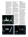
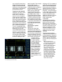
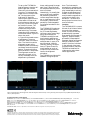
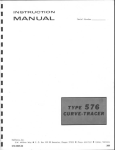
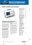
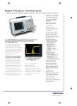
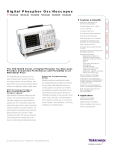
Application Note
Using the TDS3000 DPO for
Video Maintenance and
Service Measurements
Tektronix’ new TDS3000 Digital Phosphor Oscilloscopes
(DPOs) are uniquely suited to
video applications. They
offer the real-time intensitygraded display that’s so
important for video measurements, and they include the
full feature set of a digitizing
oscilloscope. With a DPO, the
NTSC baseband waveform
appears with the familiar
brightened areas on the signal peaks and the sync burst.
When viewing a full-frame
test signal, the DPO displays
the color bar waveforms with
smooth, level tops, undistorted by digital aliasing. The
TDS3000 Series DPOs deliver
uncompromised analog-style
signal viewing for video mea-
surements, as well as
advanced digital measurement and analysis features.
The TDS3000 Series also
offers the compelling advantages of compact footprint
combined with exceptional
measurement performance.
Bandwidths from 100 MHz to
500 MHz are available. The
instruments are light (only
3.2 kg) and small. Optional
battery power provides completely untethered operation.
This makes the TDS3000 an
ideal choice for video maintenance work in remote
trucks and helicopters, or
even those “behind the console” video checks in the
broadcast studio.
“Signal Present” Check is the
Most Basic
Undoubtedly, the most common video “measurement” is
the live video check. It’s
mainly intended to confirm
that the video signal is present at a given test point, say,
the output of a switcher. But
it can also reveal irregularities that affect picture
quality.
The live video check is a
basic horizontal-rate display
of the signal amplitude vs.
time. Using a TDS3000
equipped with the optional
video module, the video
check is as simple as a continuity test. Both the IRE
graticule and the video trig-
gering controls appear on the
QuickVideo menu. The Video
Autoset function automatically adjusts vertical, horizontal, and trigger settings to
bring up a waveform immediately (if there is one!). Figure
1 shows an NTSC video
waveform captured in this
manner. With the TDS3000,
the whole process takes only
a few seconds.
The TDS3000’s standard
video trigger makes it easy to
synchronize on Odd, Even,
All Fields, or All Lines of the
signal (NTSC, PAL, or
SECAM). These are standard
selections under the TRIGGER TYPE menu. Since the
video check is mainly a “signal present” test, it’s often
unnecessary to measure IRE
or mV units. Thus, the conventional oscilloscope gratic-
ule is adequate for routine
live video checks.
Line Count Triggering
Sometimes it’s necessary to
view a single line of the
video waveform. For example, the programming information in the NTSC signal is
sometimes found on Line 20.
To see this data, you must
isolate that line.
The optional Video Application Module expands the
TDS3000’s video triggering
flexibility. While the standard instrument can trigger
on All Fields or on All Lines,
the video module adds menu
selections to trigger on any
specific line number in an
NTSC, PAL, or SECAM
system.
Line Number triggering is a
first-level QuickVideo menu
selection on a video moduleequipped instrument.
Choosing “Line Number” sets up the
general-purpose knob
to scroll through the
line numbers: 1
through 263 (Odd
Lines) or 1 through
262 (Even Lines) for
NTSC; 1 through 625
for PAL and SECAM.
In this example, line
17 on an NTSC was
chosen. The line
number is displayed
prominently on the
screen, as shown in
Figure 2.
Figure 1. DPO technology brings out vivid waveform detail on the IRE graticule (available with video module).
Figure 2. Line count triggering finds line 17 on an NTSC broadcast video signal.
Automating Everyday
Measurements
The TDS3000 makes routine
video amplitude and timing
measurements easy. Using
the IRE graticule provided by
the video module, it’s a simple matter to display any part
of a video waveform and
visually measure the amplitude levels. Unlike an analog
oscilloscope, there’s no need
to convert voltage readings to
IRE levels.
Video cursors hasten the process and provide improved
accuracy. The CURSOR button brings up a menu to
select horizontal bars for
amplitude measurements.
The general-purpose knob
positions the cursors individually to bracket the desired
waveform points. Whenever
the active cursor moves, the
change in the amplitude
reading appears automatically on the screen. When the
IRE or mV graticule is
selected, the amplitude readout is expressed in the
respective units. Figure 3
shows the cursors and the
readout. A pair of vertical
bars is also available for timing measurements.
Lastly, the TDS3000 can perform automated measurements. This function is very
useful for repetitive measurements. To measure sync
width, for example, trigger on
the video waveform, then
expand the vertical and horizontal scales such that the
Figure 3. Cursor measurements allow accurate digital readout on both vertical and horizontal signal details.
sync pulse fills most of the
screen. Select the automatic
Negative Pulse Width measurement in the measurement
menu which is activated by
the MEASURE button.
Triggering for Other Standards
Obviously, not every video
system conforms to the
NTSC, PAL, or SECAM formats. As a rule, computer
video monitors, medical displays, security cameras, and
other self-contained systems
aren’t designed to interface
directly with broadcast video
equipment. These, therefore,
may not adhere to the normal
525- or 625-line standards.
Thus it is sometimes necessary to use an oscilloscope to
determine the line rate.
The TDS3000 offers an easy
solution. The first step is to
capture a stable video waveform on the screen using the
oscilloscope’s Edge trigger
(not Video trigger, since that
function is set up for stan-
dard line rates). Then use the
Vertical Bars cursors
(accessed by pressing the
CURSOR button) to measure
the time between sync
pulses. The Time Units menu
button lets you select the
reciprocal (1/time) of the
reading. Next, press the trigger MENU button. Select
Type>Video and then select
Standard>Custom as shown
in Figure 4. When this selection is made, the Scan Rate
will appear as a menu option.
In this case, select Rate 3 (25
to 35 kHz) as the scan rate.
Scan rates up to 65 kHz can
be selected.
Video Recorder “Tape Run”
Adjustments
Helical-scan video tape
recorders (VTRs) are a cornerstone of both professional
and consumer video applications. But they can be a maintenance challenge. Even the
humble VHS machine’s front
panel masks a surprisingly
complex electromechanical system.
A video recorder
reads the signal from
the video tape by
means of a rotary
scanner that houses
two playback heads
which contact the
tape. The scanner’s
rotation causes the
two heads to read
alternating interleaved tracks of information stored in a
helical pattern on the
tape.
Figure 4. Custom video trigger allows the TDS3000 to trigger on standards
such as RS343 (26.2 kHz scan rate).
Aligning a VTR is a matter of
physically adjusting the tape
path so that the tape passes
across the scanning heads in
perfect orientation. Improper
adjustment can cause line
dropouts – vertical striations
in the video image. In professional video equipment, this
may be corrected to some
degree by a dropout compensation circuit, but in any
event, dropouts are
undesirable.
Adjustments are made by
positioning a series of tape
guides while viewing the
effect on an RF signal from
the video heads. Typically an
exhaustive alignment is necessary only when the VTR
has been damaged, or if the
upper drum of the scanner
assembly has been newly
replaced.
The alignment procedure
requires an oscilloscope and
an alignment tape. Some professional VTR manufacturers
offer an optional adjustment
tool for setting the tape guide
screws.
TIP: It’s wise to run a
“known-good” tape through
the machine before starting
the actual adjustments.
When a new scanner assembly is installed, the tape
path can be grossly out of
alignment – to the point
where the first tape that goes
through the machine gets
wrinkled or scored. Protect
your costly alignment tapes;
start the alignment procedure by running a tape you
can afford to lose! Make
your initial coarse adjustments with this tape.
To set up the TDS3000 for
head alignment, start the calibration tape and connect
Channel 2 to the head switching pulse. This becomes the
trigger source. Connect Channel 1 to the output of the
high-level RF amplifier
receiving the signal from the
video heads. It’s best to set
the time base so that two, and
only two, cycles of the signal
are visible on-screen. The
“thicker” portions of the
waveform are the areas of
head switching. The screen
image should be centered on
one of these events. Figure 5a
shows the result.
In Figure 5a the heads are out
of adjustment. There are
“pinched” areas in the waveform. The ideal is to set the
alignment screws so the
waveform peaks are relatively
consistent across the top and
bottom. There should be no
gross variations in amplitude.
The alignment screws are
interactive, though, so it’s
usually necessary to do the
adjustment cycle several
times, making small changes
each time. Figure 5b shows
the waveform after the procedure is finished.
Interestingly, it’s usually better not to strive for perfectly
flat waveform peaks with
uniform amplitude throughout. A small amount of variation actually improves the
portability (interchangeability) of tapes recorded on the
machine.
The TDS3000 DPO makes an
ideal oscilloscope platform
for VTR head alignments.
Unlike any other type of digitizing oscilloscope, the
TDS3000’s analog-like realtime intensity grading can
display the familiar RF signal
envelope seen in every VTR
service manual. Without
intensity grading, the waveform in Figures 5a and 5b
would appear as a pair of
indistinct lines, almost useless for the alignment
procedure.
The TDS3000 provides tactile
feedback during the proce-
(A)
dure. The instrument’s
extraordinary waveform capture rate ensures that the display immediately tracks any
changes as adjustments are
made. A continuous adjustment, therefore, appears as a
continuous change in the
waveform – not a series of
abrupt jumps from one increment to the next.
Conclusion
The TDS3000 DPO is a versatile tool for all kinds of television and video measurements. Its unique intensitygraded display surpasses
even analog oscilloscopes in
legibility, responsiveness,
and ease of interpretation.
Standard digital oscilloscope
features, as well as videospecific functions included
in the optional video measurement module, make the
TDS3000 an ideal tool for
video service and maintenance applications.
(B)
Figure 5. Digital Phosphor technology makes video head alignment as fast and easy as using an analog oscilloscope for the job. a)RFenvelope before adjustment; b) After adjustment.
For further information, contact Tektronix:
World Wide Web: http://www.tektronix.com; ASEAN Countries (65) 356-3900; Australia & New Zealand 61 (2) 9888-0100; Austria, Central Eastern Europe, Greece, Turkey, Malta,& Cyprus +43 2236 8092 0;
Belgium +32 (2) 715 89 70; Brazil and South America 55 (11) 3741-8360; Canada 1 (800) 661-5625; Denmark +45 (44) 850 700; Finland +358 (9) 4783 400; France & North Africa +33 1 69 86 81 81;
Germany + 49 (221) 94 77 400; Hong Kong (852) 2585-6688; India (91) 80-2275577; Italy +39 (2) 25086 501; Japan (Sony/Tektronix Corporation) 81 (3) 3448-3111;
Mexico, Central America, & Caribbean 52 (5) 666-6333; The Netherlands +31 23 56 95555; Norway +47 22 07 07 00; People’s Republic of China 86 (10) 6235 1230; Republic of Korea 82 (2) 528-5299;
South Africa (27 11)651-5222; Spain & Portugal +34 91 372 6000; Sweden +46 8 477 65 00 Switzerland +41 (41) 729 36 40; Taiwan 886 (2) 2722-9622; United Kingdom & Eire +44 (0)1628 403300;
USA 1 (800) 426-2200.
From other areas, contact: Tektronix, Inc. Export Sales, P.O. Box 500, M/S 50-255, Beaverton, Oregon 97077-0001, USA 1 (503) 627-6877.
Copyright © 1998, Tektronix, Inc. All rights reserved. Tektronix products are covered by U.S. and foreign patents, issued and pending. Information in this
publication supersedes that in all previously published material. Specification and price change privileges reserved. TEKTRONIX and TEK are registered
trademarks of Tektronix, Inc. All other trade names referenced are the service marks, trademarks, or registered trademarks of their respective companies.