1
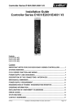
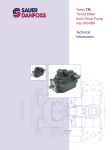
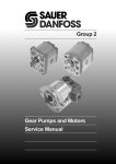
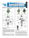
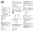
MAKING MODERN LIVING POSSIBLE
Service Manual
Closed Circuit Axial Piston
K and L Frame Variable Motors,
SAE Mount
powersolutions.danfoss.com
Service Manual
K and L Frame Variable Motors, SAE Mount
Revision history
Table of revisions
2
Date
Changed
Rev
November 2014
Danfoss layout
DA
May 2013
Add Anti-Cavitation Valve
CB
October 2010
Minor edits, new back page
CA
November 2006
Added loop flushing valve
B
July 2004
First edition
A
520L0629 • Rev DA • November 2014
Service Manual
K and L Frame Variable Motors, SAE Mount
Contents
Introduction
Technical specifications
Features
Pressure measurements
Initial start-up procedures
Fluid and filter maintenance
Troubleshooting
Minor repair
Overview..............................................................................................................................................................................................4
Safety precautions............................................................................................................................................................................4
Unintended machine movement..........................................................................................................................................4
Flammable cleaning solvents................................................................................................................................................. 4
Fluid under pressure.................................................................................................................................................................. 4
Personal safety............................................................................................................................................................................. 4
Symbols used in Danfoss literature............................................................................................................................................5
Design...................................................................................................................................................................................................5
The System circuit............................................................................................................................................................................ 6
Overview..............................................................................................................................................................................................7
Features and options...................................................................................................................................................................... 7
Specifications..................................................................................................................................................................................... 7
Operating parameters.................................................................................................................................................................... 7
Fluid specifications.......................................................................................................................................................................... 7
Displacement limiter....................................................................................................................................................................... 9
Output shafts..................................................................................................................................................................................... 9
Controls................................................................................................................................................................................................9
Control orificing...........................................................................................................................................................................9
Required tools................................................................................................................................................................................. 10
Port locations and gauge installation.....................................................................................................................................10
General ..............................................................................................................................................................................................12
Start-up procedure........................................................................................................................................................................ 12
Recommendations........................................................................................................................................................................ 13
Excessive noise and / or vibration............................................................................................................................................14
System operating hot...................................................................................................................................................................14
Won’t shift or slow to shift.......................................................................................................................................................... 14
Shaft seal replacement.................................................................................................................................................................15
Remove the shaft seal............................................................................................................................................................. 15
Inspect the components........................................................................................................................................................ 15
Install the new shaft seal........................................................................................................................................................15
Speed sensor replacement.........................................................................................................................................................15
Remove the speed sensor..................................................................................................................................................... 15
Install the new speed sensor................................................................................................................................................ 16
Speed sensor adjustment........................................................................................................................................................... 17
Adjustment and troubleshooting.......................................................................................................................................17
Loop flushing valve....................................................................................................................................................................... 17
Remove the loop flushing valve..........................................................................................................................................17
Inspect the components........................................................................................................................................................ 18
Install the loop flushing valve.............................................................................................................................................. 18
Anti-Cavitation Valve.................................................................................................................................................................... 19
Remove the anti-cavitation valve....................................................................................................................................... 19
Inspect the components........................................................................................................................................................ 19
Install the anti-cavitation valve............................................................................................................................................19
520L0629 • Rev DA • November 2014
3
Service Manual
K and L Frame Variable Motors, SAE Mount
Introduction
Overview
This manual includes information for the installation, maintenance, and minor repair of the K and L Frame
SAE Mount Variable Motors. The manual includes a description of the units and their individual
components, troubleshooting information, and minor repair procedures. Performing installation,
maintenance, and minor repair of K and L Frame Variable Motors according to the procedures in this
manual will not affect your warranty.
Performing minor repairs requires the unit to be removed from the vehicle/machine. Thoroughly clean
the unit before beginning maintenance, or repair activities. Since dirt and contamination are the greatest
enemies of any type of hydraulic equipment, follow cleanliness requirements strictly. This is especially
important when changing the system filter and when removing hoses or plumbing.
A worldwide network of Danfoss Authorized Service Centers (ASCs) is available for major repairs. Major
repairs require the removal of the unit’s endcap, which voids the warranty unless done by an ASC.
Danfoss ASCs are trained by the factory and certified on a regular basis. You can locate your nearest ASC
using the distributor locator at www.danfoss.com.
Safety precautions
Always consider safety precautions before beginning a service procedure. Protect yourself and others
from injury. Take the following general precautions whenever servicing a hydraulic system.
Unintended machine movement
W
Warning
Unintended movement of the machine or mechanism may cause injury to the technician or bystanders.
To protect against unintended movement, secure the machine or disable / disconnect the mechanism
while servicing.
Flammable cleaning solvents
W
Warning
Some cleaning solvents are flammable. To avoid possible fire, do not use cleaning solvents in an area
where a source of ignition may be present.
Fluid under pressure
W
Warning
Escaping hydraulic fluid under pressure can have sufficient force to penetrate your skin causing serious
injury and/or infection. This fluid may also be hot enough to cause burns. Use caution when dealing with
hydraulic fluid under pressure. Relieve pressure in the system before removing hoses, fittings, gauges, or
components. Never use your hand or any other body part to check for leaks in a pressurized line. Seek
medical attention immediately if you are cut by hydraulic fluid.
Personal safety
W
Warning
Protect yourself from injury. Use proper safety equipment, including safety glasses, at all times.
4
520L0629 • Rev DA • November 2014
Service Manual
K and L Frame Variable Motors, SAE Mount
Introduction
Symbols used in Danfoss literature
WARNING may result in injury
Tip, helpful suggestion
CAUTION may result in damage to product or
property
Lubricate with hydraulic fluid
Reusable part
Apply grease / petroleum jelly
Non-reusable part, use a new part
Apply locking compound
Non-removable item
Inspect for wear or damage
Option - either part may exist
Clean area or part
Superseded - parts are not interchangeable
Be careful not to scratch or damage
Measurement required
Note correct orientation
Flatness specification
Mark orientation for reinstallation
Parallelism specification
Torque specification
External hex head
Press in - press fit
Internal hex head
Pull out with tool – press fit
Torx head
Cover splines with installation sleeve
O-ring boss port
Pressure measurement/gauge location or
specification
The symbols above appear in the illustrations and text of this manual. They are intended to communicate
helpful information at the point where it is most useful to the reader. In most instances, the appearance
of the symbol itself denotes its meaning. The legend above defines each symbol and explains its purpose.
Design
K and L Frame Variable Motors (KV/LV) are low to medium power, two-position axial piston motors
incorporating an integral servo piston. They are designed for operation in both open and closed circuit
applications. KV/LV motors have an SAE-B, two bolt mounting configuration. The standard control is a
direct acting single line hydraulic control. The integral servo piston controls motor displacement.
The motors are spring biased to maximum displacement and hydraulically shifted to minimum
displacement. Minimum and maximum displacement can be set with fixed internal stops. The large
diameter servo piston allows smooth acceleration and deceleration with relatively large circuit orificing.
The motors are ideally configured for installations requiring compact packaging and optimized
plumbing, such as wheel ends. One face of the motor contains all hydraulic porting. Two standard
porting configurations are available: twin radial (side) or axial (end) O-ring boss main ports.
520L0629 • Rev DA • November 2014
5
Service Manual
K and L Frame Variable Motors, SAE Mount
Introduction
Cross section view
Bias spring
Minimum
angle
stop
Servo piston
Swashplate
Output
shaft
Cylinder
block
Shaft
seal
Endcap
Piston
Valve plate
Slipper Bearing
P101109
The System circuit
The circuit below shows the KV/LV motor in a simple closed-loop hydrostatic propel application. The
motor is driven by a Series 42 medium power axial piston pump with manual displacement control. The
motor shown uses a single line hydraulic displacement control. Control pressure applied through an
external control valve shifts the motor to minimum displacement; spring force returns the motor to
maximum displacement in the absence of control input.
System circuit diagram
High loop pressure
Case pressure
Charge/low loop pressure
Control pressure
Inlet pressure
Servo
piston
Reservior
Motor
displacement
control valve
Displacement
control spool
Pump control handle
and feedback linkage
Motor
servo
piston
Displacement
limiter
Input
shaft
Charge relief valve
Output
shaft
Charge
pump
Check valves
w/high pressure
relief valves and
bypass plunger
Filter
Pump
swashplate
6
Cylinder
block
assembly
P101 335E
520L0629 • Rev DA • November 2014
Cylinder
block
assembly
Motor
swashplate
Service Manual
K and L Frame Variable Motors, SAE Mount
Technical specifications
Overview
Specifications and operating parameters for KV/LV motors are given here for reference.
Features and options
Mount
SAE-B (LV/KV)
Cartridge (LC/KC)
Motor type
Inline, axial piston, positive displacement, two-speed variable motors
Displacement
L: 25, 30, or 35 cm3 [1.50, 1.83, or 2.14 in3] K: 38 or 45 cm3 [2.32 or 2.75 in3]
Rotation
Bidirectional
Installation position
Discretionary: Housing must always be filled with hydraulic fluid
Porting
SAE O-ring boss, axial or twin radial
SAE O-ring boss, twin radial
Output shafts
Splined 13 or 15 tooth 16/32 pitch, 0.875 in. straight
keyed, and 1:8 taper
Splined 13 or 15 tooth 16/32 pitch
Control options
Single or dual line hydraulic control
Single line hydraulic control
Displacement limiter
Fixed maximum and minimum displacement limiters available
Speed sensor
Available on L Frame SAE-B motors, in development* on K frame and cartridge motors
Loop Flushing Valve
Available
Specifications
Parameter
Unit
L25
L30
L35
K38
K45
Displacement (maximum)
cm3 [in3]
25 [1.50]
30 [1.83]
35 [2.14]
38 [2.32]
45 [2.75]
Weight (cartridge and SAE-B)
kg [lb]
0.001666
[0.001229]
0.001582
[0.001167]
0.001530
[0.001128]
0.002326
[0.001716]
0.002286
[0.001687]
Theoretical torque
N•m/bar
[lbf•in/1000psi]
0.40
[244]
0.48
[293]
0.56
[347]
0.60
[366]
0.72
[439]
Unit
L25
L30
L35
K38
K45
210 [3045]
175 [2540]
140 [2030]
210 [3045]
175 [2540]
415 [6020]
350 [5075]
300 [4350]
415 [6020]
350 [5075]
3400
3500
3600
3600
3500
15.4 [34]
kg•m2
[slug•ft2]
Mass moment of inertia of rotating
components
Operating parameters
Parameter
System pressure
continuous bar [psi]
Speed limit
(at max. disp)
continuous min-1 (rpm)
maximum
3950
4150
4300
4000
3900
Speed limit
(at min. disp)
continuous
4400
4450
4500
4650
4500
maximum
5000
5150
5300
5200
5050
Case pressure
continuous bar [psi]
maximum
maximum
2 [29]
6 [87]
Fluid specifications
Ratings and data are based on operation with premium petroleum-based hydraulic fluids containing
oxidation, rust, and foam inhibitors.
520L0629 • Rev DA • November 2014
7
Service Manual
K and L Frame Variable Motors, SAE Mount
Technical specifications
Parameter
Unit
Viscosity
mm2/sec (cSt)
Temperature
Minimum
Continuous
Maximum
[SUS]
7
[47]
12-60
[70-278]
1600
[7500]
°C [°F]
-40 [-40]
82 [180]
104 [220]
Cleanliness
Filtration efficiency
8
ISO 4406 Class 18/13 or better
suction filtration
β35-44=75 (β10≥1.5)
charge filtration
β15-20=75 (β10≥10)
520L0629 • Rev DA • November 2014
Service Manual
K and L Frame Variable Motors, SAE Mount
Features
Displacement limiter
KV/LV motors are available with a minimum angle stop. This displacement limiter is not adjustable.
Displacement limiter
Minimum angle stop
P104 242E
Output shafts
KV/LV motors have one of the following shafts. For dimensions, refer to L and K Frame Variable Motors
Technical Information, 520L0627.
• 13 tooth spline
16/32 pitch
•
ANSI B92.1 1970-Class 5
Ø 22.225 mm [.875 in]
•
Straight keyed
Ø 22.225 mm [.875 in]
•
1:5 Taper
15 tooth spline
16/32 pitch
ANSI B92.1 1970-Class 5
Controls
KV/LV motors are designed to operate in two positions: maximum and minimum displacement. The
motors are spring biased to maximum displacement and hydraulically shifted to minimum displacement.
KV/LV motors can operate with a single line or dual line control.
Control input pressure limits
Single line control
14 to 69 bar
[200 to 1000 psi]
Dual line control
14 to 35 bar
[200 to 500 psi]
Pressure applied at port X1 shifts the motor to minimum displacement. Pressure at X2 can assist the shift
to maximum displacement. Refer to the table above for control input pressure range.
Control orificing
Motors with single line controls can have optional, internal supply and drain orifices installed to regulate
control response times.
Motors with dual line controls rely on external valving and orificing to regulate shift speeds.
520L0629 • Rev DA • November 2014
9
Service Manual
K and L Frame Variable Motors, SAE Mount
Pressure measurements
Required tools
The service procedures described in this manual can be performed using common mechanic’s hand
tools. Special tools, if required are shown. Calibrate pressure gauges frequently to ensure accuracy. Use
snubbers to protect gauges.
Port locations and gauge installation
For economical reasons, the KV/LV motors do not contain any designated gauge installation ports. All
pressure measurements can be obtained by installing tee fittings to the connections at the locations
listed in the table / drawing below. Recommended gauge sizes are also listed.
Port information
Port identifier
Size
Pressure obtained
X1
[0.5625]-18 UNF-2B
Control signal
600 [10 000]
X2
[0.5625]-18 UNF-2B
Control signal
600 [10 000]
L1
[0.750]-16 UNF-2B
Case drain
10 [100]
L2
[0.750]-16 UNF-2B
Case drain
10 [100]
A
[1.0625]-12 UNF-2B
System pressure
600 [10 000]
B
[1.0625]-12 UNF-2B
System pressure
600 [10 000]
Twin radial port locations
Control port X2
Case drain port L1
System pressure port A
System pressure port B
Control port X1
Case drain port L2
P104 240E
10
520L0629 • Rev DA • November 2014
Gauge size, bar [psi]
Service Manual
K and L Frame Variable Motors, SAE Mount
Pressure measurements
Axial port locations
System pressure port A
System pressure port B
Control port X1
Case drain port L2
P104 242E
520L0629 • Rev DA • November 2014
11
Service Manual
K and L Frame Variable Motors, SAE Mount
Initial start-up procedures
General
Follow this procedure when starting-up a new motor installation or when restarting an installation in
which the motor has been removed.
W
Warning
Unintended movement of the machine or mechanism may cause injury to the technician or bystanders.
To protect against unintended movement, secure the machine or disable / disconnect the mechanism
while servicing.
Prior to installing the motor, inspect for damage incurred during shipping. Make certain all system
components (reservoir, hoses, valves, fittings, heat exchanger, etc.) are clean prior to filling with fluid.
Start-up procedure
1. Fill the reservoir with recommended hydraulic fluid. Always filter fluid through a 10 micron filter
when pouring into the reservoir. Never reuse hydraulic fluid.
2. Fill the inlet line leading from the pump to the reservoir. Check the inlet line for properly tightened
fittings and be certain it is free of restrictions and air leaks.
3. Fill the pump and motor housing with clean hydraulic fluid. Pour filtered oil directly into the upper
most case drain port.
4. To ensure the pump and motor stay filled with oil, install case drain lines into the upper most case
drain ports.
5. Install a 0 to 35 bar [0 to 500 psi] gauge in the charge pressure gauge port of the pump to monitor
system pressure during start up.
Follow recommendations in the vehicle / machine operator’s manual for prime mover start up
procedures.
6. While watching the pressure gauge, jog the prime mover or run at the lowest possible speed until
system pressure builds to normal levels (minimum 11 bar [160 psi]). Once system pressure is
established, increase to full operating speed. If system pressure is not maintained, shut down the
prime mover, determine cause, and take corrective action. Refer to Troubleshooting, page 13.
7. Operate the hydraulic system for at least fifteen minutes under light load conditions.
8. Check and adjust control settings as necessary after installation.
9. Shut down the prime mover and remove the pressure gauge. Replace plug at the charge pressure
gauge port.
10. Check the fluid level in the reservoir; add clean filtered fluid if necessary.
The motor is now ready for operation.
12
520L0629 • Rev DA • November 2014
Service Manual
K and L Frame Variable Motors, SAE Mount
Fluid and filter maintenance
Recommendations
To ensure optimum life of KV/LV products, perform regular maintenance of the fluid and filter.
Contaminated fluid is the main cause of unit failure. Take care to maintain fluid cleanliness when
servicing.
Check the reservoir daily for proper fluid level, the presence of water, and rancid fluid odor. Fluid
contaminated by water may appear cloudy or milky or free water may settle in the bottom of the
reservoir. Rancid odor indicates the fluid has been exposed to excessive heat. Change the fluid
immediately if these conditions occur. Correct the problem immediately.
Change the fluid and filter per the vehicle / machine manufacturer’s recommendations or at these
intervals:
Fluid and filter change interval
Reservoir type
Max oil change interval
Sealed
2000 hours
Breather
500 hours
Change the fluid more frequently if it becomes contaminated with foreign matter (dirt, water, grease,
etc.) or if the fluid is subjected to temperature levels greater that the recommended maximum.
Dispose of used hydraulic fluid properly. Never reuse hydraulic fluid.
Change filters whenever the fluid is changed or when the filter indicator shows that it is necessary to
change the filter. Replace all fluid lost during filter change.
520L0629 • Rev DA • November 2014
13
Service Manual
K and L Frame Variable Motors, SAE Mount
Troubleshooting
Excessive noise and / or vibration
Item
Description
Action
Check oil level in reservoir
and oil supply to the motor.
Insufficient hydraulic fluid could lead to cavitation that
would cause system noise.
Fill the reservoir to the proper level and ensure that oil
supply to the motor is adequate and the lines are
unobstructed.
Check for air in the system.
Air trapped within the system lines, or the motor itself,
could result in cavitation that would cause system noise.
Ensure that all of the system lines and components are
purged of air.
Inspect the output shaft
couplings.
A loose or incorrect shaft coupling will produce vibrations
that could result in system noise.
Ensure that the correct coupling is used and that it fits
properly onto the shaft.
Inspect the output shaft
alignment.
Misaligned shafts create excessive frictional vibration that
could result in system noise.
Ensure that the shafts are properly aligned.
Hydraulic oil viscosity above Viscosity above acceptable limits will result in cavitation
limits.
that would lead to system noise.
Replace hydraulic oil with appropriate fluid for operating
conditions. Refer to publication 5200L0463 for information
on fluid selection.
System operating hot
Item
Description
Action
Check oil level in reservoir
and oil supply to the pump.
Insufficient amount of hydraulic fluid will not meet the
cooling demands of the system.
Fill the reservoir to the proper level.
Inspect the heat exchanger,
(if so equipped).
If the heat exchanger fails, or becomes obstructed, it may
not meet the cooling demands of the system.
Ensure that heat exchanger is receiving adequate air flow
and that the heat exchanger is in good operating
condition. Repair or replace as necessary.
Check the system relief
valves.
If a system relief valve becomes unseated for an extended
period of time or fails for any other reason, the system
could become overheated.
Repair or replace any malfunctioning relief valves as
applicable and verify that the loads on the machine are not
excessive.
Item
Description
Action
Check the signal line to the
servo control port.
Obstructed or restricted flow through the servo control
signal lines could result in slow shift or no shift conditions
within the motor.
Ensure that the signal lines are not obstructed or restricted
and that signal pressure is adequate to shift the motor.
Check that the correct
supply and drain orifices are
properly installed, and are
not obstructed.
Supply and drain orifices determine the shift rate of the
Ensure that the proper control orifices are installed in the
motor. The smaller the orifice, the longer the time it takes
motor and verify that they are not obstructed. Clean or
to shift the motor. Obstruction will also increase shift times. replace as necessary.
Won’t shift or slow to shift
14
520L0629 • Rev DA • November 2014
Service Manual
K and L Frame Variable Motors, SAE Mount
Minor repair
Shaft seal replacement
Remove the shaft seal
1. Remove the snap ring (B005) retaining the shaft seal and support washer.
2. Remove the support washer (M004).
3. Carefully pry out the shaft seal (M003).
To avoid damaging the shaft during removal, install a large sheet metal screw into the chuck of a slide
hammer. Drive the screw into the seal surface and use the slide hammer to pull the seal.
4. Discard the seal.
Replacing the shaft seal
B005
M004
dM003
p
b
i
E101 061
Inspect the components
Inspect the new seal, the motor housing seal bore, and the sealing area on the shaft for rust, wear, and
contamination. Polish the shaft and clean the housing if necessary.
Install the new shaft seal
1. Cover the shaft splines with an installation sleeve to protect the shaft seal during installation.
2. Install a new shaft seal with the cupped side facing the motor. Press seal into housing until it bottoms
out. Press evenly to avoid binding and damaging the seal.
3. Install seal support washer.
4. Install snap ring.
5. Remove the installation sleeve.
Speed sensor replacement
Remove the speed sensor
1. Disconnect the speed sensor electrical connector.
2. Using an 11/16 wrench, loosen the locknut.
3. Using a 1/2 inch wrench, remove the speed sensor and o-ring from the motor.
520L0629 • Rev DA • November 2014
15
Service Manual
K and L Frame Variable Motors, SAE Mount
Minor repair
Replacing the speed sensor
Lock nut
O-ring
P104 359E
Install the new speed sensor
1. Turn speed sensor with o-ring in (CW) by hand until bottom end gently touches the speed ring.
2. Back out speed sensor (CCW) 1/4 turn. Continue backing out until the flats are 22° either side of the
motor shaft center line (20° to 30° is acceptable). Do not back out more than 3/4 turn from touching
bottom.
3. Using a 1/2 inch wrench to hold the speed sensor, torque the lock nut to 13 N•m [10 lbf•ft] with an
11/16 inch wrench.
4. Plug in electrical connection and start machine to test for proper operation.
16
520L0629 • Rev DA • November 2014
Service Manual
K and L Frame Variable Motors, SAE Mount
Minor repair
Installing the speed sensor
Speed sensor adjustment
Adjustment and troubleshooting
1. Wire configuration
Red=Power
White=Speed signal
Black=Ground (common)
Green=Direction
2. Speed signal
Check for speed output using a Volt Ohm Meter (VOM). Place VOM across the ground and speed pins
or terminals, (Black=Ground, White=Speed Signal) and set VOM to the DC Volt scale and low range.
To check for an output, turn pump or motor very slowly by hand or check output just as the prime
mover is coming to a stop. Note a voltage pulse at meter. It will likely be difficult to read exact, simply
note a pulse (approximately 60 pulses per rev). If there is no indication of a pulse, repeat installation
steps and recheck.
3. Directional signal
Check for a direction signal change using a VOM. Use the same VOM setup as in the above speed
signal check. Turn the motor slowly and note a polarity change (±) on the VOM display as you change
the motor direction.
Loop flushing valve
Remove the loop flushing valve
1. Using a 11/16 in internal hex wrench remove plug (E020) and (E010).
2. Using a 1/4 in hex wrench remove plug (E042).
3. Remove O-rings (E020B, E042A, and E010B).
520L0629 • Rev DA • November 2014
17
Service Manual
K and L Frame Variable Motors, SAE Mount
Minor repair
4. Using pliers, remove centering springs (E041, E020C, and E010C).
5. Remove spring retaining washers (E020D and E010D).
6. Remove shift spool (E030).
7. Remove orifice poppet (E040).
Loop flushing valve
E010B
E010C
E010D
E010
11/16 in
37 N·m
[27 lbf·ft]
K001
E020D
E020C
E020B
E030
E001
E020
11/16 in
E040
37 N·m
[27 lbf·ft]
E041
E042A
E042
5/8 in
27 N·m
[20 lbf·ft]
P106 512E
Inspect the components
Inspect new O-rings and the sealing area for rust, wear, or contamination. Also check springs and poppet
for wear.
Install the loop flushing valve
1. Install orifice poppet (E040).
2. Install shift spool (E030).
3. Install spring retaining washers onto springs (E020D and E010D).
4. Carefully install centering springs (E041, E020C, and E010C).
5. Install new O-rings (E010B, E020B, and E042A).
6. Using a 1/4 in hex wrench torque plug (E042) to X N•m [X ft•lbs].
7. Using a 11/16 in internal hex, torque plugs (E010 and E020) to X N•m [X lbf•ft].
18
520L0629 • Rev DA • November 2014
Service Manual
K and L Frame Variable Motors, SAE Mount
Minor repair
Anti-Cavitation Valve
Remove the anti-cavitation valve
The anti-cavitation valve is installed into the high pressure port. The high pressure port depends on
motor rotation. If rotation is counterclockwise, the high pressure port is A. If rotation is clockwise, the
high pressure port is B.
1. Using a 5/16 in internal hex wrench remove valve plug (E061). Remove and discard O-ring (E063).
2. Remove spring (E012) and relief valve (E011) from end cap.
3. Using a 5/16 in internal hex wrench remove plug (E020). Remove and discard O-ring (E020A).
Anti-cavitation valve
E020
E020A
Counter-Clockwise rotation shown.
Anti-cavitation valve is installed
in port A.
E011
E012
E063
E061
P108 714E
Inspect the components
Inspect sealing area for rust, wear, or contamination. Check spring (E012) and relief valve (E011) for wear
and damage. Relief valve (E011) is non-serviceable, replace as complete unit if damaged.
Install the anti-cavitation valve
1. Lubricate and insert relief valve (E011) and spring (E012) in original location.
2. Lubricate and install new O-ring (E063) on valve plug (E061).
3. If needed lubricate and install new O-ring (E020A) on plug (E020).
4. Using a 5/16 inch internal hex wrench to install valve plug (E061) into port with relief valve (E011).
Torque to 80 N•m [59 lbf•ft].
5. If needed using a 5/16 inch internal hex wrench to install plug (E020) into port without relief valve
(E011). Torque to 80 N•m [59 lbf•ft].
520L0629 • Rev DA • November 2014
19
Products we offer:
•
•
•
•
•
•
•
•
•
•
•
•
•
•
•
•
Bent Axis Motors
Closed Circuit Axial Piston
Pumps and Motors
Displays
Electrohydraulic Power
Steering
Electrohydraulics
Danfoss Power Solutions is a global manufacturer and supplier of high-quality hydraulic and
electronic components. We specialize in providing state-of-the-art technology and solutions
that excel in the harsh operating conditions of the mobile off-highway market. Building on
our extensive applications expertise, we work closely with our customers to ensure
exceptional performance for a broad range of off-highway vehicles.
We help OEMs around the world speed up system development, reduce costs and bring
vehicles to market faster.
Danfoss – Your Strongest Partner in Mobile Hydraulics.
Hydraulic Power Steering
Go to www.powersolutions.danfoss.com for further product information.
Integrated Systems
Wherever off-highway vehicles are at work, so is Danfoss. We offer expert worldwide support
for our customers, ensuring the best possible solutions for outstanding performance. And
with an extensive network of Global Service Partners, we also provide comprehensive global
service for all of our components.
Joysticks and Control
Handles
Microcontrollers and
Software
Open Circuit Axial Piston
Pumps
Orbital Motors
Please contact the Danfoss Power Solution representative nearest you.
PLUS+1® GUIDE
Proportional Valves
Sensors
Steering
Transit Mixer Drives
Comatrol
www.comatrol.com
Schwarzmüller-Inverter
www.schwarzmuellerinverter.com
Local address:
Turolla
www.turollaocg.com
Valmova
www.valmova.com
Hydro-Gear
www.hydro-gear.com
Daikin-Sauer-Danfoss
www.daikin-sauer-danfoss.com
Danfoss
Power Solutions (US) Company
2800 East 13th Street
Ames, IA 50010, USA
Phone: +1 515 239 6000
Danfoss
Power Solutions GmbH & Co. OHG
Krokamp 35
D-24539 Neumünster, Germany
Phone: +49 4321 871 0
Danfoss
Power Solutions ApS
Nordborgvej 81
DK-6430 Nordborg, Denmark
Phone: +45 7488 2222
Danfoss
Power Solutions
(Shanghai) Co., Ltd.
Building #22, No. 1000 Jin Hai Rd
Jin Qiao, Pudong New District
Shanghai, China 201206
Phone: +86 21 3418 5200
Danfoss can accept no responsibility for possible errors in catalogues, brochures and other printed material. Danfoss reserves the right to alter its products without notice. This also applies to
products already on order provided that such alterations can be made without changes being necessary in specifications already agreed.
All trademarks in this material are property of the respective companies. Danfoss and the Danfoss logotype are trademarks of Danfoss A/S. All rights reserved.
520L0629 • Rev DA • November 2014
www.danfoss.com
© Danfoss A/S, 2014