1
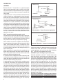
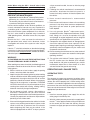
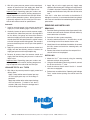
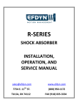
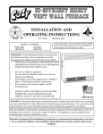
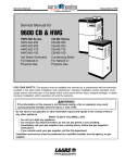
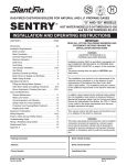
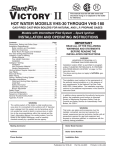
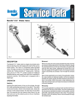
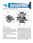
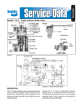
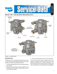
SD-03-4010
Bendix® SS-1™ Shut-Off Valve
CONTROL
PORT
CONTROL PORT
CAP NUT
1/4" P.T.
CONTROL PORT
CAP NUT O-RING
PISTON
PISTON RETURN
SPRING
PISTON O-RING
VENT PORT
VENT PLUG WITH
1/8" P.T. VENT
DELIVERY
PORT
MOUNTING
HOLES
SUPPLY
PORT
SUPPLY PORT
CAP NUT
PISTON O-RING
1/4" P.T.
DELIVERY
PORT
MOUNTING
HOLE
INLET VALVE
CAP NUT O-RING
INLET VALVE
SPRING
1/4" P.T.
SUPPLY PORT
FIGURE 1- SS-1™ SHUT-OFF VALVE
DESCRIPTION
The SS-1™ shut-off valve (figure 1) is a pilot operated,
air controlled, on-off, non-graduating, non-exhausting
pneumatic control valve. The valve is primarily used to
delay, sequence, or control airflow from various devices in
the air brake system. It can be operated either in a pilot or
automatic mode using different air connection methods.
The SS-1™ valve is a general purpose valve used in a
variety of applications on trucks, buses, tractors, trailers
and converter dollies. It is offered in a variety of pressure
settings to accommodate applications where automatic
operation is required. The most common application of
the SS-1™ valve is in the tractor protection system of a
truck tractor.
Important Note: The SS-1 ™ shut-off valve is
application specific due to its pressure settings. It is
therefore important to use the proper part number
when replacement is required. IN ADDITION: The
SS-1™ shut-off valve and SV-1™ synchro valves are
identical in appearance and similar in operation but
have substantial internal differences and must not
be confused or used interchangeably. The SV-1™
synchro valve incorporates an internal exhaust passage
through its piston, which allows delivery pressure to
be vented to atmosphere while the SS-1™ does not.
Refer to Service Data Sheet, SD-03-4020, for more
information on the SV-1™ synchro valve. Service Data
Sheets can be obtained by calling 1-800-AIR-BRAKE
or by visiting www.bendix.com on the Internet.
Two .28 inch mounting holes are provided in the die cast
zinc body for panel or frame mounting. Two steel hex cap
nuts at the ends of the cylindrical valve body retain the
internal components. All air connection ports contain pipe
threads. Lettering embossed in the valve body identifies
two of the four ports in the valve. Refer to the chart below
and figure 1.
Air Connection
Supply
Delivery
Control
Vent
Body Ident.
SUP
DEL
NONE
NONE
Thread Size
1/4” P.T.
1/4” P.T.
1/4” P.T.
1/8” P.T.
IMPORTANT: A vented, socket head vent plug is
installed in some SS-1™ valves, however, an exhaust
check valve should be installed in the threaded vent
port when the SS-1™ valve is mounted outside the cab
in unprotected environments. See Figure 2.
1/8" PIPE THREAD
Note: Either style may be installed in the SS-1™ valve
FIGURE 2 - EXHAUST CHECK VALVE STYLES
1
OPERATION
CONTROL VALVE
GENERAL
Because the SS-1™ shut-off valve is a general purpose
valve, it can be connected in the air system in a variety of
ways to accomplish its intended function. Figure 3 displays
only three of the many different connection methods that
can be used.
In general, the SS-1™ valve can either be connected in the
system to function as a pilot operated, remote mounted,
on-off valve or it can be connected in a manner that allows
the valve to operate automatically at preset pressures as
system pressure increases or decreases. Figure 3 displays
examples of air system connections. Two examples of
connections that result in pilot operation are shown and one
that illustrates automatic operation. It should be noted that
since the SS-1™ valve is a pressure sensitive valve, under
certain air system conditions it might temporarily operate in
an automatic fashion even in a system where its intended
function is that of a pilot on-off valve. Regardless of how
the SS-1™ shut-off valve is connected, the internal valve
operation is the same.
CON
SUP
RESERVOIR
RESERVOIR
Pilot Operation
TRACTOR PROTECTION
CONTROL VALVE
CON
SS-1™ VALVE
When sufficient air pressure is applied to the control port,
the control piston moves against the resistance of its return
spring. As the control piston moves, it contacts the valve
and continued piston movement drives the inlet valve from
its seat and allows supply air to flow through the body and
out the delivery port.
When air pressure is removed from the control port, the
piston return spring moves the piston away from the inlet
valve. As the piston moves, the inlet valve re-seats itself
preventing airflow to the delivery port.
If air pressure at the supply port remains constant (is not
reduced) then delivery port pressure remains equal to
supply port pressure provided that devices connected to
it do not dissipate delivery port pressure.
If supply port pressure is removed (after control pressure
is removed), then delivery port air pressure will hold the
inlet valve away from its seat against the force of the inlet
valve return spring. Air present at the delivery port will flow
through the valve body in the reverse direction, from the
delivery port, past the inlet valve, and into the supply port.
Flow will continue until the delivery port pressure (which
acts upon the area of the inlet valve) is reduced and equal
to the force exerted by the inlet valve spring. When delivery
port pressure and spring force are equal, the inlet valve
re-seats in the body and air pressure remaining in the
delivery line is “trapped” between the closed inlet valve and
air devices connected to the delivery port. The amount of
2
DEL
SUP
BRAKE VALVE
DOUBLE
CHECK VALVE
HOSE COUPLING
"GLAD HAND"
Pilot Operation - Tractor Protection Application
PILOT (controlled remotely by another valve)
With no air pressure present at the control port, supply port
air pressure, if present, along with the inlet valve spring hold
the inlet valve on its seat in the body. The piston is held
away from the inlet valve by the piston return spring.
DEL
SS-1™ VALVE
CON
SS-1™ VALVE
RESERVOIR
DEL
SUP
Automatic Operation - Common Control & Supply
FIGURE 3 TRACTOR PROTECTION SYSTEM
air pressure “trapped” is dependant upon the specific part
number of the valve. Valves used in a tractor protection
system application will “trap” less than 5 psi while other
SS-1™ valves will “trap” approximately 10 psi.
AUTOMATIC (self actuating at a preset pressure)
Automatic operation of the SS-1™ shut-off valve occurs
when the pressure at the supply and control port is the
same. This is referred to as “common control and supply”
and can be accomplished by connecting the valve’s control
port to its supply port using a pipe or tubing tee. With
common control and supply pressure, the valve opens
(delivers air) on ascending air pressure and closes on
descending pressure. The pressures at which delivery
and closure occur differ for various part numbers. Opening
and closing pressures are specified for the various part
numbers. It should be noted that as supply and control
pressure descends delivery pressure will also decrease
but will not be completely removed. Refer to the “Pilot”
operation in this section.
Important: Consult Bendix® cataloging and/or Bendix®
Engineering for specific opening and closing control
pressures when the SS-1™ valve is used in the automatic
mode. When using the SS-1™ shut-off valve in this
manner, the control signal ramp rate should be limited
by orificing or other methods. Please contact Bendix®
Engineering with specific application requirements.
PREVENTIVE MAINTENANCE
Important: Review the Bendix® Warranty Policy before
performing any intrusive maintenance procedures.
The warranty may be voided if intrusive maintenance
is performed during the warranty period.
No two vehicles operate under identical conditions, as
a result, maintenance intervals may vary. Experience is
a valuable guide in determining the best maintenance
interval for air brake system components. At a minimum,
the SS-1™ valve should be inspected every 6 months or
1500 operating hours, whichever comes first, for proper
operation.
Should the SS-1 ™ valve not meet the elements of
the operational tests noted in this document, further
investigation and service of the system or valve may be
required.
If the SS-1™ valve fails to function as described or leakage
is excessive, it should be replaced with a genuine Bendix®
service unit of the same part number, available at Bendix®
authorized parts outlets.
WARNING!
PLEASE READ AND FOLLOW THESE INSTRUCTIONS
TO AVOID PERSONAL INJURY OR DEATH:
When working on or around a vehicle, the following general
precautions should be observed at all times. Always wear
safety glasses.
1. Park the vehicle on a level surface, apply the parking
brakes, and always block the wheels.
2. Stop the engine and remove ignition key when working
under or around the vehicle. When working in the engine
compartment, the engine should be shut off and the
ignition key should be removed. Where circumstances
require that the engine be in operation, EXTREME
CAUTION should be used to prevent personal injury
resulting from contact with moving, rotating, leaking,
heated or electrically charged components.
3. Do not attempt to install, remove, disassemble or
assemble a component until you have read and
thoroughly understand the recommended procedures.
Use only the proper tools and observe all precautions
pertaining to use of those tools.
4. If the work is being performed on the vehicle’s air brake
system, or any auxiliary pressurized air systems, make
certain to drain the air pressure from all reservoirs
before beginning ANY work on the vehicle. If the
vehicle is equipped with an AD-lS® air dryer system or
a dryer reservoir module, be sure to drain the purge
reservoir.
5. Following the vehicle manufacturer’s recommended
procedures, deactivate the electrical system in a
manner that safely removes all electrical power from
the vehicle.
6. Never exceed manufacturer ’s recommended
pressures.
7. Never connect or disconnect a hose or line containing
pressure; it may whip. Never remove a component or
plug unless you are certain all system pressure has
been depleted.
8. Use only genuine Bendix ® replacement parts,
components and kits. Replacement hardware, tubing,
hose, fittings, etc. must be of equivalent size, type
and strength as original equipment and be designed
specifically for such applications and systems.
9. Components with stripped threads or damaged parts
should be replaced rather than repaired. Do not
attempt repairs requiring machining or welding unless
specifically stated and approved by the vehicle and
component manufacturer.
10. Prior to returning the vehicle to service, make certain all
components and systems are restored to their proper
operating condition.
11. For vehicles with Antilock Traction Control (ATC),
the ATC function must be disabled (ATC indicator
lamp should be ON) prior to performing any vehicle
maintenance where one or more wheels on a drive
axle are lifted off the ground and moving.
OPERATING AND LEAKAGE TESTS
OPERATING TESTS
General
Two accurate air gauges are necessary to perform these
tests. Depending upon installation, it may be necessary to
remove the valve to properly test it. When testing valves
installed in an automatic application the correct opening
pressures of the valve should be known before beginning
tests; consult vehicle manual. Refer to figure 3 and use the
appropriate Operational test.
Pilot
1. Install an accurate gauge in the supply line and the
other gauge in the delivery line.
2. With full system pressure present at the supply port of
the SS-1™ valve, apply and release full system pressure
to the control port and note that delivery pressure
increases to supply port pressure with no perceptible
lag.
3
3. With full system pressure present at the control port,
remove all pressure from the supply port. Note that
delivery port pressure is reduced to 10psi or less.
Important Note: Depending upon part number and
valve application on the vehicle, delivery port pressure
may be required to be reduced to less than 5psi. When
used in tractor protection systems, delivery pressure
is generally required to be less than 5psi in this test.
Consult the vehicle manual for specifications.
2. Apply 120 psi to the supply port only. Apply soap
solution to the exhaust port. Leakage must not exceed a
1" bubble in less than 5 seconds (100 sccm). Excessive
leakage would indicate a faulty inlet valve or inlet valve
seat.
If the SS-1™ valve does not function as described or if
leakage is excessive, it is recommended that it be replaced
with a new unit available from authorized genuine Bendix®
parts outlets.
Automatic
REMOVING AND INSTALLING
1. Install an accurate gauge in the common control and
supply line; install another gauge in the delivery line.
REMOVING
2. Gradually increase air pressure to the common supply
and control line. Note when pressure is first registered
on the delivery line gauge and record the common
control and supply pressure at that point. Compare the
recorded pressure with specifications in vehicle manual
or for the valve part number being tested. The recorded
pressure should be plus or minus 7psi of the specified
pressure.
3. Apply full system pressure to the common control and
supply and note that delivery pressure increases to
supply port pressure with no perceptible lag.
4. Remove all pressure from the common control and
supply. Note that delivery port pressure is reduced to
10psi or less.
Important Note: Depending upon part number and
valve application on the vehicle, delivery port pressure
may be required to be reduced to less than 5psi.
LEAKAGE TESTS - ALL TYPES
1. With 120 psi air pressure present in supply, control and
delivery ports:
Apply a soap solution around control port cap
nut and supply port cap nut. No leakage is
permitted.
1. Read the Warning Section previously presented in this
manual and make certain to block and hold vehicle by
means other than air brakes.
2. Drain the air brake system completely.
3. Clean the exterior of the SS-1™ shut-off valve, as well
as the fittings and air lines attached to the valve.
4. Identify the air lines to facilitate reinstallation, disconnect
the lines, remove and retain the mounting bolts, and
then the valve.
5. Remove the exhaust check from the vent port if the
shut-off valve was so equipped.
INSTALLING
1. Mount the SS-1™ valve securely using the mounting
hardware retained during removal.
2. Using the identification made during removal, connect
the air lines to the SS-1™ valve.
3. Install the exhaust check valve if the SS-1™ shut-off
valve was so equipped.
4. Perform tests as outlined in the "Operating and Leakage
Tests" section before placing the vehicle back into
service.
Apply soap solution to the exhaust port; leakage
must not exceed a 1" bubble in less than 5
seconds (100 sccm). Excessive leakage would
indicate faulty piston o-rings.
4
BW2539 © 2006 Bendix Commercial Vehicle Systems LLC. All rights reserved. 1/2006 Printed in U.S.A.