
1
OPERATION & MAINTENANCE MANUAL TDA-110P Aerosol Penetrometer Air Techniques International Division of Hamilton Associates, Inc 11403 Cronridge Drive Owings Mills, MD 21117 USA TEL 410-363-9696 FAX 410-363-9695 www.atitest.com TDA-110P Air Techniques International Page Intentionally Left Blank ii 1800103 Rev C 1800103 Rev C Air Techniques Incorporated TDA-110P Table of Contents 1. 2. Utility Requirements....................................................................................................... 1 Specifications ................................................................................................................. 2 2.1. 2.2. 2.3. 2.4. 2.5. 2.6. 2.7. 2.8. 3. 4. Control Location and Functions ................................................................................... 4 Features and Options................................................................................................... 10 4.1. 4.2. 4.3. 4.4. 4.5. 4.6. 5. Proper Fill Level ................................................................................................................................... 13 Generator Regulator Pressure ............................................................................................................. 13 Generator Fill ....................................................................................................................................... 13 Machine Startup Sequence.......................................................................................... 14 8.1. 8.2. 8.3. 8.4. 8.5. 8.6. 8.7. 8.8. 9. Input Air ................................................................................................................................................ 11 Exhaust Connection ............................................................................................................................. 11 Communications Port ........................................................................................................................... 11 User Interface Port ............................................................................................................................... 11 Initial Setup ................................................................................................................... 12 Filling Methods ............................................................................................................. 13 7.1. 7.2. 7.3. 8. Test Types ........................................................................................................................................... 10 Alarm Parameters ................................................................................................................................ 10 Alarm (audible) ..................................................................................................................................... 10 Usage Timer......................................................................................................................................... 10 Data Output .......................................................................................................................................... 10 User Interface Port ............................................................................................................................... 10 Installation .................................................................................................................... 11 5.1. 5.2. 5.3. 5.4. 6. 7. Physical Characteristics ......................................................................................................................... 2 Operational Requirements ..................................................................................................................... 2 Aerosol Generation ................................................................................................................................ 2 Aerosol Detection ................................................................................................................................... 2 Filter Test Flow Measurement ............................................................................................................... 2 Pressure Measurement .......................................................................................................................... 2 Efficiency Measurement ......................................................................................................................... 2 Communications Port ............................................................................................................................. 3 Power On ............................................................................................................................................. 14 System Initialization ............................................................................................................................. 14 System Version .................................................................................................................................... 14 Input Air ................................................................................................................................................ 14 System Vacuum ................................................................................................................................... 14 Check Liquid Level ............................................................................................................................... 14 System Warm up ................................................................................................................................. 14 Initial Calibration .................................................................................................................................. 14 Test Menu...................................................................................................................... 15 9.1. Start Cycle............................................................................................................................................ 15 9.2. Test Loading ........................................................................................................................................ 15 9.3. Testing ................................................................................................................................................. 15 9.4. Test End ............................................................................................................................................... 15 9.5. Failed Check ........................................................................................................................................ 15 9.6. Calibration Prompt ............................................................................................................................... 15 9.7. .................................................................................................................................................................... 15 10. Standby Mode ............................................................................................................... 16 11. Calibration Sequence ................................................................................................... 17 11.1. 11.2. 11.3. Test Flow Setup Menu ......................................................................................................................... 17 Test Flow Setting ................................................................................................................................. 17 Penetration Setup Menu ...................................................................................................................... 17 12. Setup Menu ................................................................................................................... 19 12.1. 12.2. 12.3. Select Pressure Units .......................................................................................................................... 19 Maximum Percent Penetration Variable (Alarm Point) ........................................................................ 19 Minimum Percent Penetration Variable (Alarm Point) ......................................................................... 19 iii TDA-110P 12.4. 12.5. 12.6. 12.7. 12.8. 12.9. 12.10. 12.11. 12.12. 12.13. Air Techniques International 1800103 Rev C Maximum Resistance Variable (Alarm point) ....................................................................................... 19 Minimum Resistance Variable (Alarm point) ........................................................................................ 20 Test Flow Tolerance Variable (Alarm Point) ........................................................................................ 20 Load Time Variable .............................................................................................................................. 20 Extended Load Time Variable.............................................................................................................. 20 Sample Time Variable .......................................................................................................................... 20 Open Time Variable ......................................................................................................................... 21 Cycles to Calibration ........................................................................................................................ 21 Concentration Reference Alarm ...................................................................................................... 21 Set Date and Time ........................................................................................................................... 21 13. Maintenance.................................................................................................................. 22 13.1. 13.2. 13.3. 13.4. Initial Setup .......................................................................................................................................... 22 Definitions and Features ...................................................................................................................... 22 Scheduled Maintenance ...................................................................................................................... 22 Spare Parts List ................................................................................................................................... 22 14. Maintenance Menu Structure ...................................................................................... 23 14.1. 14.2. 14.3. 14.4. 14.5. 14.6. 14.7. 14.8. 14.9. 14.10. 14.11. 14.12. 14.13. 14.14. Maintenance Menus ............................................................................................................................. 23 Gravimetric ........................................................................................................................................... 25 Res Offset ............................................................................................................................................ 26 Flow Balance........................................................................................................................................ 27 LSC Check ........................................................................................................................................... 27 LSC Offset............................................................................................................................................ 28 View Sensor ......................................................................................................................................... 29 Cal Sensor ........................................................................................................................................... 31 Primary (HIGH) Flow Sensor Setup ..................................................................................................... 33 Auxiliary (LOW) Flow Sensor Setup ................................................................................................ 35 ID ..................................................................................................................................................... 37 Console ............................................................................................................................................ 37 Security ............................................................................................................................................ 37 Setting the Machine ID .................................................................................................................... 38 15. Console Commands ..................................................................................................... 39 16. LSC Maintenance ......................................................................................................... 40 16.1. 16.2. 16.3. Photomultiplier Tube Replacement ...................................................................................................... 40 Cleaning ............................................................................................................................................... 40 Aligning ................................................................................................................................................ 41 Appendix A. Appendix B. Appendix C. Appendix D. Appendix E. Appendix F. Appendix G. Appendix H. Appendix I. Appendix J. Appendix K. Dip Switch Settings .................................................................................... 42 TDA-110P Operating Parameters .............................................................. 43 Default Settings .......................................................................................... 44 Fault and Error Messages .......................................................................... 45 Remote Mode Operation ............................................................................ 47 USER INTERFACE Circuit Example .......................................................... 48 4B Lite Aerosol Generator ......................................................................... 49 PAO-4 Safety Data Sheet ........................................................................... 50 Blower Motor............................................................................................... 56 Flow Sensor Operation and Service Manual ............................................ 57 Manual Revision ......................................................................................... 58 iv 1800103 Rev C Air Techniques Incorporated Page Intentionally Left Blank v TDA-110P 1800103 Rev C Air Techniques Incorporated TDA-110P 1. Utility Requirements Control Unit 2 Compressed Air - Clean, dry, compressed airflow rate of 10 SCFM at 80 psig (283 slpm @ 5.6 kg/cm ) NOTE: Maintain the compressed air temperature between 60 and 90 degrees Fahrenheit (70 to 75 degrees is recommended). It is highly recommended that a coalescing filter and pressure regulator be installed between the plant airline and the air inlet. Power – Control Unit - Stable electrical power at 115 VAC, 50/60 Hz (a power line conditioner and surge protection is recommended). 230 VAC, 50/60 Hz is optional. NOTE: A dedicated power circuit is recommended for stable machine operation. Consult the manufacturer. Ambient Conditions - Temperature controlled environment: 68 to 85 degrees Fahrenheit recommended. Humidity controlled environment: 45 – 75% relative humidity recommended. Aerosol Unit 2 Compressed Air - Clean, dry, compressed airflow rate of 10 SCFM at 80 psig (283 slpm @ 5.6 kg/cm ). Three separate lines required. NOTE: Maintain the compressed air temperature between 60 and 90 degrees Fahrenheit (70 to 75 degrees is recommended). It is highly recommended that a coalescing filter and pressure regulator be installed between the plant airline and the air inlet. Blower Motor Power - Stable electrical power at 208-230/460 VAC, 3-Phase, 60 Hz. NOTE: A dedicated power line is recommended for stable machine operation. Consult the manufacturer. Ventilation - Exhaust the air with a duct capable or directing 500 cubic feet per minute at a resistance of ≤1 inch of water (see Section 5.2 - Exhaust Connection for details). Ambient Conditions - Temperature controlled environment: 68 to 85 degrees Fahrenheit recommended. Humidity controlled environment: 45 – 75% relative humidity recommended. NOTE: High ambient temperatures may create particle instability. 1 TDA-110P Air Techniques International 1800103 Rev C 2. Specifications 2.1. Physical Characteristics Control Unit Size Weight 24 in wide x 30 in deep x 72 in high 210 lbs Aerosol Unit Size Weight 120 in wide x 44 deep in x 54 in high 750 lbs System Blower Size Weight 22 in wide x 28 in deep x 17 in high 150 lbs 2.2. Operational Requirements Control Unit Power Compressed Air Input System Blower Power System Exhaust 115 VAC, 60 Hz, 2.5A 220 VAC, 50 HZ, 1.25A (Optional) 2 10 SCFM @ 80 psig (283 slpm @ 5.6 kg/cm ) 208-230 VAC-3 Phase, 50/60 Hz or 460 VAC – 3 Phase, 50/60 Hz Aerosol is exhausted from the system, while not operating in the Test Mode, at a rate of approximately 400 cfm (cubic feet per minute) 2.3. Aerosol Generation Technique Compressed Air Input Reagent Diameter Geo Std Deviation Concentration Pneumatic nebulization with impaction using “Cold” 4 centistokes PAO 2 10 SCFM @ 80 psig (283 slpm @ 5.6 kg/cm ), 2 lines required PAO-4 (poly alpha olefin – 4 centistokes) (See Appendix I) 0.185 ± .020 micrometer CMD (meets 42 CFR Part 84) < 1.6 (meets 42 CFR Part 84) 3 20 milligrams per cubic meter (mg/m ) minimum. 2.4. Aerosol Detection Technique Dynamic Range Accuracy Sample Flow Rate Near forward light scattering 3 0.0001 to 200 milligrams per cubic meter (mg/m ) ± 1% Partial flow through detector, 45 LPM (liters per minute) 2.5. Filter Test Flow Measurement Technique Accuracy Range NIST traceable flow meter ± 1.0% 10 to 330 cfm (cubic feet per minute) @ 21.1°C, 760 mm Hg 2.6. Pressure Measurement Technique Accuracy Range Electronic pressure transducer ± 1.0% of full scale 0 to 100 mm water column (0 to 3.94 inches water column) 2.7. Efficiency Measurement Media Test Flow Operating Range 10 – 330 cfm (cubic feet per minute) @ 21.1°C, 760 mm Hg Efficiencies to 99.9995% 2 1800103 Rev C Air Techniques Incorporated 2.8. Communications Port Serial Port Data Bits Baud Rate Parity Stop Bit Flow Control Cable required RS-232 8 9600 None 1 Xon/Xoff Null modem configuration (shown below) 3 TDA-110P TDA-110P Air Techniques International 1800103 Rev C 3. Control Location and Functions Before operating this unit, familiarize yourself with its features and functions. Each number in the photo is keyed to the list below. 8 READY Indicator light 11 % Penetration window 12 Resistance window 9 FAULT Indicator light 13 Test Flow window 10 FAIL Indicator light 7 VF Display window 6 Function keys 5 Chuck Close Switches 4 1800103 Rev C Air Techniques Incorporated TDA-110P 17 Exhaust Damper meter 1 Power ON 2 Power indicator 3 Power OFF 4 Emergency Stop 15 Test Flow Rate meter 16 Exhaust Damper adjustment 14 Test Flow Rate adjustment 19 Aerosol Generator ON/OFF Switch Pneumatic Tubing Connections-Enclosure Lower Right-side (39) Generator Pilot (34) Chuck Pilot (38) Damper Close (35) Aerosol UP Stream (32) Resistance UP Stream (31) Chuck Supply (37) Damper Open (36) Aerosol DWN Stream (33) Resistance DWN Stream 5 TDA-110P Air Techniques International 1800103 Rev C 20 AC Power Input 28 RS232 Communication Port 1. 2. 3. 4. 5. 6. 7. 8. 9. 10. 11. 12. 13. 14. 15. 16. 29 User Interface port Power ON – Green push button turns system power and air on Power Indicator – Indicates that the power is on when lit Power OFF – Red push button turns system power and air off Emergency Stop – Push to turn off system power and air. Rotate clockwise to re-set. Chuck Close Switches – Used to actuate test chuck movement. Press simultaneously to close the test chuck. Pressing either switch will stop the function being performed and open the Test Chuck Function Keys – Four function keys, labeled A through D, used to select or change options. The display window shows the function of each key. VF Display Window – Displays system information and function key options Ready Indicator – Green light indicates the unit is ready to start a new test Fault Indicator – Yellow light indicates a pre-calibration condition or system fault (see Table 3 – System Faults) Fail Indicator – Red light indicates a failed test parameter % Penetration Window – Displays the % penetration readings during testing and displays set points when in Setup mode Resistance Window – Displays the resistance (pressure drop) during testing in units of inches H 2O Flow Rate Window – Displays the flow rate during testing in cfm Test Flow Damper Adjustment – pneumatic control of flow control damper. Used in conjunction with the exhaust damper for flow rate adjustment Test Flow Damper Meter – displays the position of the flow control damper in 0-100 % open. Exhaust Damper Adjustment – controls opening and closing of the exhaust damper. Used in with the test flow damper for flow rate adjustment 6 1800103 Rev C Air Techniques Incorporated TDA-110P 17. Exhaust Damper % Open Meter – displays position of exhaust damper in 0 -100 % open 19. Aerosol Generator ON/OFF switch – Turns on the aerosol generator pilot air pressure to enable the aerosol generators. 20. AC Power Input – Recessed 3-prong, AC power inlet connector for control unit 21. Generator compressed air supply – Regulated compressed air supply for system aerosol generator 30 Main compressed air inlet port 24 Main Power Relay 22 Electronic Enclosure 25 AC line Filter 23 Main PCBA 7 TDA-110P Air Techniques International 1800103 Rev C 26 Upstream Pressure Transducer port - P2 27 Downstream Pressure transducer port - P1 22. Electronics Enclosure – contains the control relays and PCBA (printed circuit board assemblies) 23. Main PCBA – microprocessor circuit board. Location of operating program E-Prom and 8 bit microprocessor 24. Main Power Relay (CR1) – maintains power to the control unit circuits, relays and valves after actuation by the main Power ON switch 25. AC Line Filter –power input line conditioner to remove transient voltage fluctuations 26. Upstream Pressure Transducer Port P2 - Used to determine the filter pressure differential 27. Downstream Pressure Transducer Port P1 - Used to determine the filter pressure differential 28. Communication Port – A DB-9 female connector for RS-232 computer interface used for connection to a PC serial port 29. User Interface Port - Used to interface with external control equipment 30. Main Pressure Input Port - Input for system compressed air supply 31. Chuck Supply– Compressed air used to raise test chuck to its open position 32. Resistance UP Stream - Used to determine the filter pressure differential 33. Resistance DWN Stream - Used to determine the filter pressure differential 34. Chuck Pilot - Compressed air used to lower test chuck to its closed position 35. Aerosol UP Stream – Sample line for measuring 100% aerosol challenge used for testing 36. Aerosol DWN Stream – Sample line for measuring aerosol challenge level penetrating through the filter under test 8 1800103 Rev C Air Techniques Incorporated TDA-110P 21 Generator Supply 41 Virtual Impactor 40 Aerosol Generator Damper Open – Opens the aerosol damper. Damper Close – Closes the aerosol damper. Generator Pilot – Provides air pilot signal to turn on aerosol generators. Aerosol Generator - Cold nebulization aerosol generator. Two units included. Virtual Impactor – Impactor to control aerosol particle size output by removing large particles. Two units included. 42. Flow Sensor Control Unit – Contains the control electronic and adjustments for the flow sensor signal to the control unit. 43. Flow Sensor – Measures the air speed for the flow measurement. 37. 38. 39. 40. 41. 43 Flow Sensor 42 Flow Sensor Control Unit 9 TDA-110P Air Techniques International 4. Features and Options 4.1. Test Types Percent Penetration Resistance (available units of measure are mm water column, inches of water, Pascals, or kilopascals) Test Flow Rate (CFM) 4.2. Alarm Parameters Alarm points can be set and enabled by the user (see Setup Menu beginning at Section 12.5 for details). If an enabled alarm point is reached, the test fails, the display flashes, and the audible alarm sounds. 4.3. Alarm (audible) The alarm is used for prompting the operator and indicating system actions and faults. The time interval during which the audible alarm functions is set by adjusting the “Open Time” variable. 4.4. Usage Timer When the unit is first turned on, the penetration display shows the total time, in hours, that the unit has been in an energized state. 4.5. Data Output Outputs test data through the RS-232 communications port. Port settings are 9600, N, 8, 1 4.6. User Interface Port The port allows the user to interface with ancillary equipment for controlling or monitoring the unit. (See Section 5.4 – User Interface Port & Appendix F – Remote Mode Operation) 10 1800103 Rev C 1800103 Rev C Air Techniques Incorporated Table 1 & Appendix G & H for connection details). 5. Installation 5.1. Input Air Ready (Output) – Indicates that the unit is ready to start a new test Before connecting the compressed air line, check the line for any fluids or unwanted contaminants. Pass (Output) – Indicates a passed test NOTE: Pre-filtering is recommended. Connect the compressed air sample line to the Main Pressure Input Port shown in the Figure on page 7, Item No. 30 and the two 4Blite generators. Fail (Output) – Indicates a failed test Fault (Output) – Indicates a system fault (See Appendix D –Fault & Error Messages) In Cal (Output) – Indicates when the unit is in penetration calibration CAUTION: For the user’s safety, make sure all the connections are secure. External Start (Input) – The signal used to start a test cycle from an external source. A pulse of 524V DC for a minimum 0.100 seconds will start a test cycle. 5.2. Exhaust Connection Connect each of the two 6–inch exhaust hoses (user supplied) to the system exhaust ducts. Exhaust draw should be as minimal as possible. NOTE: This port is isolated from the unit to protect against external damage. WARNING: Excessive exhaust draw will cause unstable aerosol concentration resulting in faulty and/or inconsistent results. Table 1 – Connector Pins & Functions Connector Pin 1 2 3 4 5 6 7 8 9 5.3. Communications Port The communications port is a standard 9-pin male (DTE configuration). Using a standard RS-232 null modem cable, connect the unit to your PC serial port. Configure your serial port to the following settings: Baud Data Bits Parity Stop Bit Flow Control TDA-110P 9600 8 None 1 Xon/Xoff 5.4. User Interface Port The outputs are an open collector type capable of sinking 50 mA for a non-inductive load (see 11 Function External Start NC Fault Pass NC Ground Ready Fail In Cal / Busy TDA-110P Air Techniques International 1800103 Rev C 6. Initial Setup 1) Verify that all the input compressed air supplies are connected. 2) Plug the unit into the proper power source. 3) Fill both the 4Blite generators to the fill line (middle) with the oil specified in the Factory Settings sheet (see Section 7 - Filling Methods). NOTE: Over or under filling the generator will result in an unstable aerosol source. WARNING: If any liquids are used other than that which is specified on the Factory Settings sheet, the generator will not function to specification. 4) Follow the Machine Startup Sequence (Section 8) until the Test menu (Section 9) is reached. At this point the TDA-4Blite generators should be on and each of the regulators located at the generators adjusted to 30 psi. 5) Check the system settings against the Factory Settings sheet included with this manual. 6) Power the unit off by pressing the red push button. 7) Perform the test set up at this time (Section 12 – Setup Menu) to adjust user specific testing parameters. 12 1800103 Rev C Air Techniques Incorporated 7. Filling Methods 7.1. Proper Fill Level PAO Moil must always be used with this equipment. ATI 4Blite Laskin aerosol generators tanks are marked with a fill line at the center point of the reservoir. The PAO oil level should always be maintained within ± 0.25 inches of the fill line. WARNING: Do not fill generator more than 0.50 inches from the fill line. 7.2. Generator Regulator Pressure The 4B lite generator regulators must be set at 30 psi when the regulators are functional. Switch the Aerosol Generators switch to ON at the control panel and check to ensure the regulators are set to 30 psi. 7.3. Generator Fill Remove the generator fill caps from each generator and fill with PAO oil noting the fill line on the sight glass. Replace the fill cap. WARNING: NEVER operate the equipment without the fill caps in place. . 13 TDA-110P TDA-110P Air Techniques International 1800103 Rev C 8. Machine Startup Sequence In this manual, the following conventions are used: 8.4. Input Air Awaiting Air <Function> indicates the function key that is pressed. This usually corresponds to the switch label on the bottom line of the display. If no label is present, the switches are designated “A”, “B”, “C”, and “D”, from left to right. xx indicates a variable displayed value. [P] Indicates the penetration display. [R] Indicates the resistance display. [F] Indicates the test flow display. <CLOSE> Indicates that both of the chuck close switches should be pressed simultaneously. <OPEN> Indicates that pressing either chuck close switch should open the chuck. The unit is waiting for the input air. 8.5. System Vacuum Awaiting Vacuum The unit is waiting for the system vacuum. 8.6. Check Liquid Level Check the liquid level in generators and fill if necessary. Remove any liquid in the drip jars before continuing. NOTE: Pressing either chuck close switch cancels the function being performed and opens the chuck. Check Liquid Level CONT 8.1. Power On Turn on the unit power by pressing the green button on the control unit then turn on the blower and aerosol generator using the switches. <CONT> Continue with Startup 8.7. System Warm up The system will now enter an eight minute warm-up to allow the aerosol output to stabilize. The standard warm-up period is eight minutes. 8.2. System Initialization Immediately after power on, the system will enter an initialization sequence lasting approximately 15 seconds. The progress of the initialization is indicated by a series of periods on the second line of the display. SYSTEM WARMUP BYPASS <BYPASS> Continue with Startup Initializing System ......... 8.8. Initial Calibration After a system start the system must perform the penetration calibration sequence (Section 11). After this initial calibration is completed, the machine will be ready for use and will display the screen shown in Section 9. 8.3. System Version ATI 110P Ver n.n UNIT ID 9999 n.n 9999 [P] Software Version The unit id assigned to this unit. (See Section 15.21 for information on setting the unit id.) Hours the unit has been in operation 14 1800103 Rev C Air Techniques Incorporated TDA-110P 9. Test Menu After successful initialization, the TDA-110P will be ready to test samples. indicated by the operator panel status lights. The displayed values are: [P] [R] [F] 9.1. Start Cycle At this point the machine is idle and can either initiate a test, setup operating parameters (limits and timings), calibrate the LSC, or enter a standby state. If all three of the test parameters are within the limits specified for the test the sample passes and the machine will return to the Start Cycle menu. START CYCLE STBY <SETUP> <CAL> <STBY> <CLOSE> CAL Test % Penetration reading Test Resistance reading Test Flow reading If any of the test parameters are outside the specified limits, the sample will be failed, the red fail indicator will be illuminated, the display for the failing parameter(s) will flash, and system will display the Failed Check screen (See Section 9.5) if the Failed Check option is enabled. SETUP Enters the Setup Menu (Section 12). Enters the Calibration Sequence. (Section 11) Enters into Standby Mode Close chuck to begin testing Results of a test will remain on the displays until the next operation is started. 9.2. Test Loading 9.5. Failed Check The system is waiting the designated load time prior to testing. The Failed Check is used to confirm a failed test. This check is optional and may be bypassed if the Failed Lockout dipswitch is set or if the unit is in the Automatic Testing mode. (See Appendix A for setting locations.) ** LOADING ** 9.3. Testing ** FAILED ** Test readings are displayed for the total sample time in approximately one-second intervals. The chuck will automatically open at the end of the test cycle if the sample time has been set. CONT <CONT> ** TESTING ** [P] [R] [F] Returns to Start Cycle 9.6. Calibration Prompt This prompt will appear if the “Cycles to Calibration” setup option has been selected (Section 12.14) and the specified number of test cycles has been reached. Test % Penetration reading Test Resistance reading Test Flow reading Cal Penetration? 9.3.1.1.1. NOTE: If the sample time is disabled, the test continues until either chuck switch is pressed to end the test. YES <YES> <NO> 9.4. Test End At the completion of the test the last sample parameter readings will be displayed on the operator panel and the success or failure of the test 9.7. 15 NO Enter the penetration calibration process (See Section 11.7) Skip the calibration and return to the Start Cycle menu. If the calibration is skipped, the prompt will not appear until the number of cycles is reached again. TDA-110P Air Techniques International 10. Standby Mode The Standby Mode allows the user to turn off the aerosol generator when the system is idle. If desired the blower may be disabled using the switch on the control panel. STANDBY CONT <CONT> Reactivates the aerosol generator. You must also ensure that the blower and aerosol generator switches are on. If the machine has been in standby mode for more than 10 minutes the System Warmup screen (see Section 8.7) will be displayed. If the system has been in standby for 10 minutes or less, the following screen (“Wait”) will be displayed. WAIT This screen indicates that the system is waiting for the aerosol generator to stabilize. The screen will be displayed for approximately 30 seconds after which the system will return to the system start screen (see Section 9) and will be ready for further testing 16 1800103 Rev C 1800103 Rev C Air Techniques Incorporated TDA-110P 11. Calibration Sequence NOTE: Any time the chuck is closed, pressing either chuck switch will abort the function being performed. 11.1. Test Flow Setup Menu This menu is used to adjust the filter test flow. This screen will only be displayed if the flow has already been set. If the machine has just been started, this screen will be bypassed and you will continue with the screen in section 11.6. * CALIBRATING * * Loading * SET FILTER TEST FLOW This screen is displayed while loading chuck with aerosol. YES NO <Yes> <No> Enters into Test Flow Setting menu Skips to Penetration Setup menu * CALIBRATING * 11.2. Test Flow Setting 100% Setting Insert the test filter into the chuck. INSERT FILTER; This screen is displayed while measuring the 100% concentration level. CLOSE EXIT <CLOSE> <EXIT> 11.3.2. Display Concentration Level Close chuck to continue Returns to Test Flow Setup (Section 11.5) This value is only displayed if the Concentration Reference Alarm option is set in the Setup menu. NOTE: Any time the chuck is closed; pressing either chuck switch will abort the function being performed and open the chuck. Adjust the Exhaust Damper and Test Flow valve controls until the desired flow is reached. Conc = nnn.nnnn CONT <CONT> Flow = 9.9999 11.3.3. Resistance Tare Setting The unit establishes the resistance tare value. (This is the inherent resistance of the air path with no filter in place.) ENTER 9.9999 Test Flow (cfm) NOTE: Allow the flow reading to stabilize for 10-15 seconds before accepting the setting. <ENTER> Accepts flow setting, opens chuck, and continues to Penetration Setup menu Clear Chuck & Close 11.3. Penetration Setup Menu <CLOSE> This procedure establishes the response of the LSC to zero and 100% levels of aerosol. Close chuck to proceed NOTE: Any time the chuck is closed, pressing either chuck switch will abort the function being performed. 11.3.1. 100% Setting The unit establishes the 100% value. Insert Filter and Close <CLOSE> Continues with the calibration process. Close chuck to proceed 17 TDA-110P Air Techniques International 11.3.4. Zero Setting * CALIBRATING * 0 SETTING This screen is displayed while the system establishes the zero reference. 11.3.5. Complete Calibration WAIT This screen is displayed while the system completes the calibration process. The system will then return to the screen from which the calibration was initiated. 18 1800103 Rev C 1800103 Rev C Air Techniques Incorporated TDA-110P 12. Setup Menu The Setup Menu is a series of screens that are used to establish the operating parameters of the machine. <UP> <DWN> <DSBL> General Notes: A number of the parameters are numeric. These parameters are entered by incrementing or decrementing a starting value. If the increment or decrement buttons are held down, the rate of the change increases and will continue to increase as long as the button is held. To return to the slower rate of increment or decrement, release the button and press it again. <ENBL> <ENTER> Some parameters, such as alarm limits, may be disabled. If a limit is disabled, no alarm will be raised if the parameter exceeds the specified limits. If it is possible to disable an alarm or function an additional button, ENBL/DSBL (Enable/Disable), is available. When the button is labeled ENBL, its function is to enable the parameter. When the button is labeled DSBL, its function is to disable the parameter. Disabled parameters are shown as all dashes (“-“). 12.3. Minimum Percent Penetration Variable (Alarm Point) Pen Min = 999.9999 % UP 999.9999 12.1. Select Pressure Units <UP> <DWN> <DSBL> The TDA-110P can display pressure in one of four units: inches of H2O (inH2O), millimeters of H2O (mmH2O), Pa, and kPa. Use this choice to select the desired unit. Pres. Unit now mmH20 NEXT <NEXT> <CONT> <ENBL> CONT <ENTER> Selects the next pressure unit. The top line will change to reflect the new unit. Saves the current unit choice and proceeds with the setup process. UP 999.9 <UP> <DWN> <DSBL> Pen Max = 999.9999 % 999.9999 DSBL DSBL ENTER The alarm will be activated at readings less than this set point (Range: -0.0005 to 99.9). If the digits are replaced by dashes (“-“), the alarm has been disabled. Increases the setpoint. Decreases the setpoint. Disable the alarm function. When pressed, “DSBL” changes to “ENBL” and the digits are replaced by dashes (“-“). Enable the alarm function. When pressed, “ENBL” changes to “DSBL” and the digits of the limit are displayed. Accepts the setting and enters the next Setup menu screen Res Max = 12.2. Maximum Percent Penetration Variable (Alarm Point) DWN DWN 12.4. Maximum Resistance Variable (Alarm point) NOTE: The units in subsequent pressure displays will reflect the selected unit choice made here. For the purposes of this manual, we will assume that inH20 is the selected unit. UP 0.0001 to 99.9). If the digits are replaced by dashes (“-“), the alarm has been disabled. Increases the setpoint. Decreases the setpoint. Disable the alarm function. When pressed, “DSBL” changes to “ENBL” and the digits are replaced by dashes (“-“). Enable the alarm function. When pressed, “ENBL” changes to “DSBL” and the digits of the limit are displayed. Accepts the setting and enters the next Setup menu screen ENTER The alarm will be activated at readings greater than this set point (Range: 19 999.9 mmH2O DWN DSBL ENTER Alarm activated at readings greater than this set point (Range: 0 – 250 mmH2O) Increases the variable Decreases the variable Disable the alarm function. When pressed, “DSBL” changes to “ENBL” and the digits are replaced by dashes (“-“). TDA-110P <ENBL> <ENTER> Air Techniques International Enable the alarm function. When pressed, “ENBL” changes to “DSBL” and the digits of the limit are displayed. Accepts the setting and enters the next Setup menu screen <ENTER> 1800103 Rev C Accepts the setting and enters the next Setup menu screen 12.6. Test Flow Tolerance Variable (Alarm Point) Flow Tol = 12.5. Minimum Resistance Variable (Alarm point) Res Min = UP 999.9 <UP> <DWN> <DSBL> <ENBL> UP 99 999.9 mmH2O DWN DSBL ENTER <UP> <DWN> <DSBL> Alarm activated at readings less than this set point (Range: 0 – 250 mmH2O) Increases the variable Decreases the variable Disable the alarm function. When pressed, “DSBL” changes to “ENBL” and the digits are replaced by dashes (“-“). Enable the alarm function. When pressed, “ENBL” changes to “DSBL” and the digits of the limit are displayed. <ENBL> <ENTER> <ENTER> 12.7. Load Time Variable The load time variable is the time from when the chuck is closed to when the unit begins to measure the properties of the sample. This time is used to establish a stabile aerosol flow. Load Time = UP 99 <UP> <DWN> ENTER> UP 99 <UP> <DWN> <DSBL> NOTE: This variable must be greater than the normal Load Time variable. <ENBL> 99 sec <ENTER> 99 <UP> <DWN> Accepts the setting and enters the next Setup menu screen Sample Time = Sets the time from when the chuck is closed to when the test starts to sample. The extended load time is used if the previous test failed or if a calibration has just been performed. DWN Alarm activated at test flow readings +/this value (Range: 1 – 10) Increases the variable Decreases the variable Disable the alarm function. When pressed, “DSBL” changes to “ENBL” and the digits are replaced by dashes (“-“). Enable the alarm function. When pressed, “ENBL” changes to “DSBL” and the digits of the limit are displayed. Accepts the setting and enters the next Setup menu screen NOTE: If the sample time is disabled, the test continues until either chuck switch is pressed to end the test. ENTER 12.8. Extended Load Time Variable UP ENTER The sample time variable is the length of time the test is sampled in one-second intervals. The unit displays the test results at approximately one second intervals during the testing. Load time in seconds. (Range 1 – 60) Increases the variable Decreases the variable Accepts the setting and enters the next Setup menu screen Ext Ld Time = DSBL 12.9. Sample Time Variable 99 sec DWN DWN ± 99 cfm ENTER Extended Load Time in seconds. (Range the value set for the load time to 100) Increases the variable Decreases the variable 20 DWN 99 sec DSBL ENTER Time in seconds. (Range: 1 – 3600) Increases the variable Decreases the variable Disable the alarm function. When pressed, “DSBL” changes to “ENBL” and the digits are replaced by dashes (“-“). Enable the alarm function. When pressed, “ENBL” changes to “DSBL” and the digits of the limit are displayed. Accepts the setting and enters the next Setup menu screen 1800103 Rev C Air Techniques Incorporated 12.10. Open Time Variable Concentration is The open time variable is used to delay the start of the next test cycle Open Time = UP 99.9 <UP> <DWN> <ENTER> 99.9 ENTER <DSBL> <SET > <ENTER> 9999 <DSBL> <UP> <DWN> <DSBL> <ENBL> <ENTER> DWN DSBL ENTER Disables the alarm function Activates the alarm function Accepts the setting and enters the next Setup menu screen. 12.13. Set Date and Time Set/Enter screen This screen allows the user to select whether they want to change the date/time recorded in the machine or proceed to the next screen. Sets the number of tests that must be completed between prompts for system recalibration (See Section 9.6). When the specified number of tests has been completed, the system will prompt the operator to recalibrate the penetration. This same interval is used to update the temperature and barometric pressure if the ”Auto” selection is made for flow compensation is selected. (Section 12) UP DSBL SET 12.11. Cycles to Calibration 9999 ENTER Concentration is Open Time in seconds. (Range 0 to 60) Increases the variable. Decreases the variable. Accepts the setting and enters the next Setup menu screen. Cycles to Cal = SET DSBL sec DWN TDA-110P mm/dd/yy hh:mm SET ENTER mm dd yy Month (1 to 12) Day of Month (1 to last day of month) Last two digits of year. (The first two digits are assumed to be “20”.) hh Hour of the day using the 24 hour clock. (0 to 23) mm Minutes in the hour. (0 to 59) <SET> Enters the date/time setting mode below. <ENTER> Accepts the setting and enters the next Setup menu screen. Date/Time Setting Mode In the date/time set mode, each group of digits (month, day, year, etc.) is incremented or decremented in turn by the <UP> and <DWN> buttons. Pressing the <CONT> button will advance to the next group of digits. CTS ENTER (Range 1 – 9999) disables the function Increases the variable Decreases the variable Disable the alarm function. When pressed, “DSBL” changes to “ENBL” and the digits are replaced by dashes (“-“). Enable the alarm function. When pressed, “ENBL” changes to “DSBL” and the digits of the limit are displayed. Accepts the setting and enters the next Setup menu screen mm/dd/yy hh:mm 12.12. Concentration Reference Alarm UP After the Penetration Setup menu, the test 3 aerosol concentration in mg/m is displayed. A concentration error will occur if the concentration falls outside of the concentration alarm point window. (See Section 15.15 – Gravimetric Setup in the Maintenance section) <UP> <DWN> <CONT> 21 DWN CONT Increases the variable Decreases the variable Advance to the next group of digits. After the minutes group, returns to the Set/Enter Screen. TDA-110P Air Techniques International 1800103 Rev C 13. Maintenance Weekly 13.1. Initial Setup The following maintenance routines should be run to familiarize the user with these functions as well as set up the unit for operation in the user’s environment: Flow Balance, Pressure Check (not pressure setup), and Gravimetric Test. Check the chuck for debris and clean as needed. Check pressure differential gauges on blower pre-filter and HEPA filter. Replace if pressure exceeds 0.5in. Monthly 13.2. Definitions and Features Gravimetric – Used to measure and set the system aerosol concentration level and alarm points (See Section 15.15 - Gravimetric Setup) Pressure Check and Setup – Used to check or recalibrate the system pressure sensor to an external source (See Sections 15.18 - Pressure Check and Pressure Setup) Biannually Security – Used to prevent changes to the alarm values or critical load and sample times (See Section 15.13 - Security) LSC Check (Light Scattering Chamber) – Used to adjust the LSC after maintenance and for general trouble shooting (See Section 15.14 - LSC Check) Check the system tubing for oil or particle buildup and replace if necessary. Check the pressure sensor against an external source and calibrate if necessary. Replace the Test Flow After-filter (carbon/HEPA filter). Replace the Reference (HEPA) filter. Annually Dip Switches – Used for initial system setup (See Appendix A - Dip Switch Settings) 13.3. Scheduled Maintenance Clean the LSC (see Section 7 - LSC Maintenance). Have the mass flow meter calibrated. 13.4. Spare Parts List The following provides a one-year supply. NOTE: Scheduled maintenance is based on an 8hour operating day. If operating time is increased, the frequency of maintenance operations should be increased as well. 1 ea. 1 ea. 12 ft. 12 ft. 30 ft. 1 ea Daily Check the liquid level in the aerosol generator and refill as needed. Check the liquid level in the drain jar and empty if necessary. Check the compressed air input filter for liquid and drain if necessary. 1 ea Check blower inlet for obstructions and clean as necessary. 2 ea 22 HEPA -Cap 75 mm, w/barbs Part # 5500128 HEPA –Cap 75 mm, Part # 5500122 Clear ½” Tubing, Part # 5200155 Clear 1/4” Tubing, ATI Part # 5200138 Black 3/8” Tubing, ATI Part # 5200140 MERV8 2 inch Pre-filter, Flanders, Precisionaire, Pre Pleat 62R, Part # 2242BPFTPR 24 x 24 x 12 HEPA Filter, Flanders Precisionaire, Superflow 2K, Part # SF24-8G2-GG Sanitary Clamp Silicone Gasket, ATI Part # 4300127. 1800103 Rev C Air Techniques Incorporated TDA-110P Exit Maintenance? 14. Maintenance Menu Structure 14.1. Maintenance Menus The menu structure within the Maintenance portion of the TDA-100P operating program is laid out in a loop. Using the <Next> and/or <Prev> keys allows navigation through the loop until arriving again at the entry point. Selecting <Cont> enters the feature displayed in the topmost row. The top level Maintenance features are “Gravimetric”, “Res Offset”, “Flow Balance”, “LSC Check”, “LSC Offset”, “View Sensor”, “Cal Sensor”, “ID”, “Console” & “Security”. After “Security” the menu loops back to “Gravimetric”. Yes No A B <Yes> <No> C D Exits Maintenance and restarts the unit. Returns to Maintenance entry menu Maint: Res Offset Prev Next Cont Back A B C D <Prev> Returns to Gravimetric selection The 100P will enter maintenance mode in three circumstances: <Next> Proceeds to Flow Balance selection 1. In response to an error such as an LSC failure that requires use of maintenance mode to test and recalibrate the system. <Cont> Enters Res Offset <Back> Prompts for Maintenance exit 2. If the internal memory becomes corrupted. This will require that all the maintenance calibration routines be performed to restore the machine to an operational state. Maint: Flow Balance 3. After a restart of the machine. To enter maintenance mode after a restart, wait until the System Version is displayed, and then press and hold the leftmost function key, ‘A’, until the display changes or a short beep is heard. Prev Next Cont Back A B C D <Prev> Returns to Res Offset selection <Next> Proceeds to LSC Check selection <Cont> Enters Flow Balance 4. To re-initialize ALL values stored in the units battery-backed RAM substitute the rightmost function key, ‘D’, for the ‘A’ key called out in step 3 above. <Back> Prompts for Maintenance exit Maint: LSC Check * Please note that once this initialization has been performed the previous values cannot be recovered. Top level Maintenance entry menu Prev Next Cont Back A B C D <Prev> Returns to Flow Balance selection Maint: Gravimetric <Next> Proceeds to LSC Offset selection Prev Next Cont Back A B C D <Cont> Enters LSC Check Back> <Prev> Proceeds to Security selection <Next> Proceeds to Res Offset selection <Cont> Enters Gravimetric test <Back> Prompts for Maintenance exit Selecting <Back> from the Maintenance entry menu will result in a Yes or No prompt, as shown next to confirm the intent to leave Maintenance. 23 Prompts for Maintenance exit TDA-110P Air Techniques International 1800103 Rev C Maint: LSC Offset Prev Next Cont Back A B C D Maint: ID <Prev> Returns to LSC Check selection Prev Next Cont Back A B C D <Next> Proceeds to View Sensor selection <Prev> Returns to Cal Sensor selection <Cont> Enters LSC Offset <Next> Proceeds to Console selection <Back> Prompts for Maintenance exit <Cont> Enters ID <Back> Prompts for Maintenance exit Maint: View Sensor Prev Next Cont Back A B C D Maint: Console <Prev> Returns to LSC Offset selection Prev Next Cont Back A B C D <Next> Proceeds to Cal Sensor selection <Prev> Returns to ID selection <Cont> Enters View Sensor <Next> Proceeds to Security selection <Back> Prompts for Maintenance exit <Cont> Initiates Console <Back> Prompts for Maintenance exit Maint: Cal Sensor Prev Next Cont Back A B C D Maint: Security <Prev> Returns to View Sensor selection Prev Next Cont Back A B C D <Next> Proceeds to ID selection <Prev> Returns to Console selection <Cont> Enters Cal Sensor <Next> Proceeds to Gravimetric test <Back> Prompts for Maintenance exit <Cont> Enters Security <Back> Prompts for Maintenance exit 24 1800103 Rev C Air Techniques Incorporated Loading -- 14.2. Gravimetric TDA-110P ### sec left Flow = ##.# Abort Maint: Gravimetric A Prev Next Cont Back A B C D B C D “Sec left” is the time remaining in the Gravimetric test until completion. “Flow=##.#” is the sample flow passing through the weighed sample in liters per minute. If the flow decreases during the test due to loading, this may be adjusted using the Flow Adjustment control. A gravimetric reading is used to determine the aerosol concentration of the unit. Measuring the amount of aerosol collected and the total airflow during the sample time performs this as explained below. <Abort> Stops the test in progress and returns to Maintenance entry menu. <Prev> Proceeds to Security selection <Next> Proceeds to Res Offset selection Loading Complete <Cont> Enters Gravimetric test <Back> Prompts for Maintenance exit AvgFlow = ##.# A B Enter Exit C D Loading Complete Returns to Maintenance entry menu. TotFlow = ###.# A Wait 30 second countdown begins before entry into Gravimetric test D Determine the amount of weight increase for the media used during the gravimetric test by subtracting the starting weight from the ending weight measured after completion of “Loading” Exit C C <Cont> proceeds to the next step Close Chuck to Start B B Cont “TotFlow = ###.#” is the total volume of sample flow that passed through the pre-weighed media during the Gravimetric test period. Record this number. 30 seconds remaining A D <Cont> proceeds to the next step <Enter> Enters Gravimetric test routine <Exit> C “AvgFlow = ##.#” is the average sample flow present during the Gravimetric test period. Gravimetric Test A B Cont Ending weight – starting weight = weight increase D Divide the weight increase by the recorded TotFlow value. The result obtained is the aerosol concentration expressed as weight of aerosol (ug) per volume of air (l). Weigh a sample of high efficiency media large enough to completely fill the test fixture opening and record the weight. No sample air flow should be able to pass through the test fixture without passing through the media. Weight increase ÷ TotFlow = concentration in ug/l Place the weighed media in the test fixture. With the media in place depress both actuator switches at the same time to initiate the Gravimetric test. 25 TDA-110P Air Techniques International 1800103 Rev C <UP> Increases the concentration limit Store New Values? <DWN> Decreases the concentration limit Yes No A B C <ENTER>Accepts the value displayed as the lower concentration limit and continues to the next step. D The calculated “Lo Con” value displayed will be the valued entered for “Con” - 20%. This value may be increased or decreased at the discretion of the enduser. <Yes> Proceeds to the next step, memory storage routine, to set and capture the gain levels necessary to achieve a 100% response from the available aerosol. <No> Exits the Gravimetric test menu and returns to the Maintenance entry menu. Clear Chuck & Close Con. = Exit ### ug/l UP DWN A B A ENTER C D <DWN> Decreases the displayed Conc. Value <ENTER> Accepts the entered Conc. Value as the calculated aerosol concentration and continues to the next step. The operating program then immediately returns to the top level Maintenance entry menu. ### ug/l DWN A B 14.3. Res Offset ENTER C Maint: Res Offset D “Hi Con. = ### ug/l” is the upper concentration limit for the “Con Check” variable. <UP> Increases the concentration limit <DWN> Decreases the concentration limit <ENTER>Accepts the value displayed as the upper concentration limit and continues to the next step The calculated “Hi Con” value displayed will be the valued entered for “Con” + 20%. This value may be increased or decreased at the discretion of the enduser. Lo Con. = DWN A B ENTER C Prev Next Cont Back A B C D <Prev> Proceeds to Maintenance entry menu <Next> Proceeds to Flow Balance selection <Cont> Enters Res Offset menu <Back> Prompts for Maintenance exit ### ug/l UP D After a loading period, the microprocessor will adjust the sensitivity of the LSC to obtain the required voltage level. At the end of this adjustment the display will briefly show the 100% voltage level. The Sample/Clear valve then changes to the clear position to provide the LSC with particle free air. After a short delay the Clear 0 baseline voltage (stray light) will be stored to memory and briefly displayed. <UP> Increases the displayed Conc. value UP C Make sure that nothing is in the test fixture. Depress both actuator switches at the same time to initiate the completion of this routine. “Con. = ### ug/l” is calculated using the values obtained during the gravimetric test. Hi Con. = B D “Lo Con. = ### ug/l” is the lower concentration limit of the “Con Check” variable. 26 1800103 Rev C Res Offset - Air Techniques Incorporated TDA-110P #.## mm/H2O Set Dsbl A B Flow is now Exit C D “Res Offset #.## mm/H2O” is the resistance offset value currently stored in memory. <Enbl/Dsbl> Toggles between enabled and disabled states. The Enabled state displays the stored offset value (±) to be applied to each test result. The Disabled state displays -----. A B B C D The flow balance is adjusted by alternating between the Sample and Clear states, using the ON and OFF selections, while observing the sample flow display and adjusting the gate valve installed immediately below the 0 Reference filter. The flow balance setting is complete when the displayed values during each state match with ± 0.1 LPM. Enter C A EXIT <Exit> Returns to the Maintenance entry menu #.## mm/H2O Dwn OFF <OFF> Disables the Sample/Clear solenoid valve. CLEAR displayed. Sample flow path is through the 0 Reference filter. <Exit> Returns to the Maintenance entry menu Up ON <ON> Enables the Sample/Clear solenoid valve. Sample displayed. Sample flow path is through the test fixture. <Set> Proceeds to the Res Offset adjustment menu below Res Offset - SAMPLE (CLEAR) D 14.5. LSC Check “Res Offset #.## mm/H2O” is the resistance offset value currently stored in memory. Maint: LSC Check <UP> Increases the Res Offset value <DWN> Decreases the Res Offset value <ENTER>Accepts the value displayed as the Res Offset and returns to the previous screen. 14.4. Flow Balance Maint: Flow Balance Prev Next Cont Back A B C D Returns to Gravimetric selection <Next> Proceeds to Flow Balance selection <Cont> Enters Res Offset menu Next Cont Exit A B C D <Prev> Returns to Gravimetric selection <Next> Proceeds to Flow Balance selection <Cont> Enters Res Offset menu <Exit> Returns to the Maintenance entry menu The menu is used to observe the LSC operating voltages for basic troubleshooting purposes. This routine is used to correct for air flow resistance differentials between the sample flow path and the clear airflow path. This is done to minimize response lag in the mass flow meter. <Prev> Prev LSC Check - Close EXIT A B C D <Exit> Returns to the Maintenance entry menu <Back> Prompts for Maintenance exit The test fixture should be closed at this time. Closure may be accomplished using either manual actuators or an EXT Start signal sent to the User Port. Close Chuck The test fixture should be closed at this time. Closure may be accomplished using either manual actuators or an EXT Start signal sent to the User Port. 27 TDA-110P Air Techniques International LSC Voltage = <Enbl> indicates the feature is disabled and pressing the key will enable the LSC Offset #.#### ON EXIT A B C <Exit> Returns to the Maintenance entry menu. D “LSC Voltage = #.####” displays the voltage output signal for the LSC. <ON>/<OFF> Enable/Disables the Sample/Clear solenoid valve. <ON> Sample valve is enabled. The displayed voltage represents the signal generated by the 100% sample of the available aerosol concentration. <OFF> Sample valve is disabled. The displayed voltage represents the signal generated by sampling particle free air through the 0 Reference filter. This is the “straylight” voltage. <Exit> Returns to the Maintenance entry menu 14.6. LSC Offset Maint: LSC Offset Prev Next Cont Exit A B C D Used to access and set the LSC Offset variable. The value is used to correct for signal shifts in the LSC output caused by DC power variations during operation. <Prev> Returns to LSC Check selection <Next> Proceeds to View Sensor selection <Cont> Enters LSC Offset menu <Exit> Returns to the Maintenance entry menu Note: Under most applications this variable is more easily and accurately set using Console mode access. LSC Offset - -### Set Dsbl A B “LSC Offset Offset value. disabled state. Exit C 1800103 Rev C D -###” displays the stored LSC A display of “------“indicates a <Set> Enters LSC Offset adjustment routine. <Dsbl>/<Enbl> Enables or disables the LSC Offset feature. <Dsbl> indicates the feature is enabled and pressing the key will disable the LSC Offset. 28 1800103 Rev C Air Techniques Incorporated 14.7. View Sensor Insert Clear Filter Maint: View Sensor CONT A <CONT> B C D Used as an acknowledgement that a known filter has been placed in series with the LSC inet port, replacing the Sample/Clear valve sample line. The Sample/Clear valve will energize at this time. C Cont Exit A B C D <Prev> Returns to LSC Offset selection <Next> Proceeds to Cal Sensor selection <Cont> Enters View Sensor menu D The TDA-100P will sample for a period of time to stabilize and record the LSC output signal in this sampling state. Selecting Pressure Remove Filter CONT <CONT> Next The menu is intended as a troubleshooting aid and allows viewing of the raw input voltages as interpreted by the 100P microprocessor. B A Prev <Exit> Returns to the Maintenance entry menu Finding Zero A TDA-110P B C D Prev Next Cont Back A B C D <Prev> Proceeds to LSC sensor output <Next> Proceeds to Flow senor output <Cont> Enters Pressure sensor output <Back> Returns to the Maintenance entry menu Used as an acknowledgement that the previously installed filter has been removed and the LSC inet port tubing connections restored. The Sample/Clear valve will de-energize at the appearance of this screen. Voltage = #.#### V Exit A B C D “Voltage = #.### V” displays the output signal being received from the differential pressure transducer. Finding Zero <Exit> Returns to the initial View Sensor menu, “Selecting Pressure”. A B C D The TDA-100P will sample for a period of time to stabilize and record the LSC output signal in this sampling state before returning to the Maintenance entry menu. Selecting Flow Prev Next Cont Back A B C D <Prev> Proceeds to Pressure sensor output <Next> Proceeds to Aux Flow senor output <Cont> Enters Flow sensor output <Back> Returns to the Maintenance entry menu 29 TDA-110P Air Techniques International 1800103 Rev C Voltage = #.#### V Temp = ##.## C Exit A B C (Raw = #.#### V ) D “Voltage = #.### V” displays the output signal being received from the mass flow meter.. A B Exit C D “Temp = ##.## C” displays the output signal being received from the PCBA mounted temperature sensor converted to degrees centigrade using the conversion constant stored in memory. <Exit> Returns to the initial View Sensor menu, “Selecting Pressure”. “(Raw = #.#### V)” displays the PCBA mounted temperature sensor output as a voltage. Selecting Aux Flow Prev Next Cont Back A B C D <Exit> Returns to the initial View Sensor menu, “Selecting Pressure”. This feature is currently not used and is intended for future applications. <Prev> Proceeds to Flow sensor output <Next> Proceeds to Temp senor output <Cont> Enters Aux Flow sensor output Selecting Baro Pres <Back> Returns to the Maintenance entry menu Voltage = #.#### V Prev Next Cont Back A B C D <Prev> Proceeds to Temp sensor output <Next> Proceeds to LSC senor output <Cont> Enters Baro Pres output <Back> Returns to the Maintenance entry menu. Exit A B C B.P. = ##.## inHg D “Voltage = #.### V” displays the output signal being received from the auxiliary mass flow meter, if installed and enabled. (Raw = #.#### V ) <Exit> Returns to the initial View Sensor menu, “Selecting Pressure”. “Temp = ##.## inHg” displays the output signal being received from the PCBA mounted barometric pressure sensor converted to degrees inches of mercury using a fixed conversion constant. A . B Exit C D “(Raw = #.#### V)” displays the PCBA mounted barometric pressure sensor output as a voltage. Selecting Temp Prev Next Cont Back A B C D <Prev> Proceeds to Aux Flow sensor output <Next> Proceeds to Baro Pres senor output <Cont> Enters Temp output <Exit> Returns to the initial View Sensor menu, “Selecting Pressure”. <Back> Returns to the Maintenance entry menu. 30 1800103 Rev C Air Techniques Incorporated TDA-110P Selecting LSC Prev Next Cont 14.8. Cal Sensor Back Maint: Cal Sensor A B C D <Prev> Proceeds to Baro Pres sensor output <Next> Proceeds to Pressure senor output <Cont> Enters LSC sensor output LSC=#.#### Up Dwn Samp Exit A B C D Next Cont Back A B C D WARNING: The screens associated steps within this section are used to verify and/or calibrate the sensors used during the operation of the TDA100P. Known calibration standards, specific supplies and fixtures may be required and should be readily available <Back> Returns to the Maintenance entry menu DAC = ##, Prev Only Trained and Authorized personnel should access these features. Improper or partial completion of the steps outlined will render the TDA-100P inoperable until successful completion. The View LSC screen is intended as the primary working maintenance interface for light scattering chamber. Using this screen, all necessary output is available to enable optical alignment, PMT alignment & troubleshooting as well as leak testing. <Prev> Returns to View Sensor selection <Next> Proceeds to ID selection <Cont> Enters Cal Sensor menu <Back> Returns to the Maintenance entry menu. The test fixture should be closed at this time. Closure may be accomplished using either manual actuators or an EXT Start signal sent to the User Port. Selecting Pressure “DAC = ##” displays the stored gain sensitivity setting for the LSC photomultiplier tube “LSC = #.####” displays the output voltage from the light scattering chamber under its current conditions. Prev Next Cont Back A B C D <Prev> Proceeds to Gravimetric test. See Section 14.2 <Up> Increases the DAC value by one at each press. Changes made using this feature are not retained upon exit. <Next> Proceeds to Flow calibration menu <Cont> Enters Pressure sensor calibration <Dwn> Decreases the DAC value by one at each press. Changes made using this feature are not retained upon exit. <Back> Returns to the Maintenance entry menu <Samp>/<Cler> Enable/Disables the Sample/Clear solenoid valve. Pressure Check? <Samp> Sample valve is disabled. The displayed voltage represents the signal generated by sampling particle free air through the 0 Reference filter. This is the “straylight” voltage. Yes No A B C D <Yes> enters a pressure verification menu. <No> Proceeds to Pressure sensor calibration. <Cler> Sample valve is enabled. The displayed voltage represents the signal generated by the 100% sample of the available aerosol concentration. <Exit> Returns to the initial View Sensor menu, “Selecting Pressure”. 31 TDA-110P Air Techniques International 1800103 Rev C Set for – 0 - WC ** Are You Sure? ** CONT A B C D Disconnect both lines from the pressure transducer so that the transducer inlets are bleeding to atmosphere (0” water column). Attach a pressure calibrator and pressure source in series with the transducer inlet port labeled P2 (uppermost). The pressure calibrator/source should not be sourcing pressure to the transducer at this stage. <CONT> enters a pressure verification routine. Pressure #.#### YES NO A B DEFAULT C D <YES> Proceeds to pressure calibration <NO> Returns to Cal Sensor entry menu. <DEFAULT> Loads a default system pressure value to memory and returns to Cal Sensor entry menu. NOTE: Loading “Default” values is not recommended except in extreme circumstances. Always be prepared to select <Yes> and set up the pressure transducer with a NIST traceable pressure calibrator. Exit Set for – 0 - WC A B C D CONT “Pressure #.###” displays the output signal being received from the pressure sensor in mm/H2O calculated using the conversion constant stored in memory. A B C D Disconnect both lines from the pressure transducer so that the transducer inlets are bleeding to atmosphere (0” water column). Close any open bleed valves on the pressure calibrator/source and slowly apply pressure to the pressure transducer inlet port labeled P2. Attach a pressure calibrator and pressure source in series with the transducer inlet port labeled P2 (uppermost). The pressure calibrator/source should not be sourcing pressure to the transducer at this stage. Allow the pressure to stabilize at 10, 40 & 80 mm/H2O and compare the TDA-100P pressure to the pressure calibrator displayed pressure. The TDA-100P pressure must correspond to the pressure calibrator display within ± 0.5 mm/H2O at all three (3) pressure set points. <CONT> enters a pressure verification routine. Record - 0 - <Exit> Proceeds to the Pressure Setup menu #.#### ENTER A Pressure Setup A B Exit Enter C D B C D “Pressure #.###” displays the output signal being received from the pressure transducer as voltage. <ENTER> Stores the transducer output signal at atmospheric pressure memory. <Exit> Returns to Cal Sensor entry menu. <Enter> Proceeds to pressure sensor calibration. If all pressure set point readings in the pressure check menu were acceptable, restore the pressure transducer tubing connections and press ‘C’ <EXIT>. If any pressures set point readings in the pressure check menu were unacceptable, press ‘D’ <ENTER>. 32 1800103 Rev C Air Techniques Incorporated 14.9. Primary (HIGH) Flow Sensor Setup Set Pressure “Flow1” Input on PCBA Feature used to enter Flow Sensor calibration data. CONT A B C D Note – if the flow sensor has been calibrated by its manufacturer then this procedure is not required. <CONT> This screen allows a user controlled pause for adjustment of the external pressure applied to the transducer. The applied pressure value, as measured by the pressure calibrator, should be in the upper 25% of the transducer range (between 75 to 100 mm/H2O). Press CONT when the reading displayed on the calibrator has stabilized within the acceptable range. Record Pres. Selecting Flow #.#### B C Prev Next Cont Back A B C D <Prev> Proceeds to Pressure sensor calibration <Next> Proceeds to Aux Flow senor calibration <Cont> Enters Flow sensor calibration <Back> Returns to the Maintenance entry menu ENTER A TDA-110P Adj Flow to Zer0 D CONT “Pressure #.###” displays the output signal being received from the pressure transducer as voltage. A EXIT B C D <ENTER> Records the transducer output signal at the applied pressure to memory. <CONT> Continues to the flow meter zero output signal display screen. NOTE: It is important that the exact value displayed on the pressure calibrator in mm/H2O be noted at the moment <ENTER> is pressed. This value is required for the next step. <Exit> Returns to the initial View Sensor menu, “Selecting Pressure”. At this step the blower should be OFF to prevent any air currents from being detected.. Flow Zero = Input Pres = UP DWN A B ###.# SET ENTER C A displayed B C D <SET> Stores the displayed voltage to memory. <Exit> Returns to the initial View Sensor menu, “Selecting Pressure”. <UP> Increases the displayed pressure calibration point. the EXIT “Flow Zero = #.####” V displays the flow meter signal being received with no air flow through the sensor. D “Input Pres = ## #.#” displays the pressure that will be use as the calibration point determined in the preceding step. <DWN> Decreases calibration point. #.#### Select Cal Type pressure VEL <ENTER> Stores the entered value to memory and returns to the initial View Sensor menu, “Selecting Pressure”. A VOL B C D <VEL> Proceeds to the Velocity based calibration routine using feet per minute (fpm) and the crosssectional area where the sensor is installed. . 33 TDA-110P Air Techniques International <VOL> Proceeds to the Volumetric based calibration routine using cubic feet per minute (cfm). VOLUMETRIC CALIBRATION When Flow = ### cfm UP DN A B ENTER C D <UP> Increases the displayed flow calibration value in cfm. <DWN> Decreases the displayed flow calibration value in cfm. <ENTER> Stores the entered value to memory. Flow Volts = #.#### UP DWN A B ENTER C D “Flow Volts = #.####” displays a user entered Ref Flow voltage (5.00VDC typical) from a NIST Traceable calibration sheet.. <UP> Increases the displayed flow calibration voltage. <DWN> Decreases the displayed flow calibration voltage. <ENTER> Stores the entered value to memory and returns to CAL SENSOR menu. VELOCITY CALIBRATION When Flow = ####.# fpm UP DN A B ENTER C D <UP> Increases the displayed flow calibration point in feet per minute. <DWN> Decreases the displayed flow calibration point in feet per minute. <ENTER> Stores the entered value to memory. 34 1800103 Rev C 1800103 Rev C Air Techniques Incorporated Flow Volts = Enable Aux Flow Sens #.#### UP DWN A B ENTER C D “Flow Volts = #.####” displays a user entered Ref Flow voltage (5.00VDC typical) from a NIST Traceable calibration sheet. YES NO A B <Yes> A B B C D <CONT> Continues to the flow meter zero output signal display screen. ENTER C EXIT A #.##” DWN Enters Aux Flow sensor calibration CONT <ENTER> Stores the entered value to memory. UP D Adj Aux Flow to Zero <DWN> Decreases the displayed flow calibration voltage. = C <No> Returns to the Maintenance entry menu <UP> Increases the displayed flow calibration voltage. Duct Dia. TDA-110P <Exit> Returns to the initial View Sensor menu, “Selecting Pressure”. D “Duct Dia. = #.####” displays the diameter to be used for calculating the cross-sectional area (inches). At this step the blower should be OFF and cap the probe to eliminate any air currents from being detected. <UP> Increases the displayed duct diameter. Flow Zero = <DWN> Decreases the displayed duct diameter. #.#### SET <ENTER> Stores the entered value to memory and returns to CAL SENSOR menu. EXIT A B C “Flow Zero = #.####” V” displays the flow meter signal being received with no air flow through the sensor. 14.10. Auxiliary (LOW) Flow Sensor Setup “Flow2” Input on PCBA <SET> Stores the displayed voltage to memory. Feature used to enter Flow Sensor calibration data for the auxiliary flow sensor. <Exit> Returns to the initial View Sensor menu, “Selecting Pressure”. Note – if the flow sensor has been calibrated by its manufacturer then this procedure is not required. Select Cal Type Selecting Aux Flow VEL Prev Next Cont Back A B C D <Prev> Proceeds to Flow sensor calibration <Next> Proceeds to Temp senor calibration <Cont> Enters Aux Flow sensor calibration D A VOL B C D <VEL> Proceeds to the Velocity based calibration routine using feet per minute and the crosssectional area where the sensor is installed. <VOL> Proceeds to the Volume based calibration routine using cubic feet per minute. <Back> Returns to the Maintenance entry menu 35 TDA-110P Air Techniques International 1800103 Rev C VOLUMETRIC CALIBRATION <ENTER> Stores the entered value to memory. When Flow = ### cfm Duct Dia. UP DN A B C = #.##” ENTER UP DWN D A B ENTER C D “Duct Dia. = #.####” displays the diameter to be used for calculating the cross-sectional area (inches). <UP> Increases the displayed flow calibration value in cfm. <DWN> Decreases the displayed flow calibration value in cfm. <UP> Increases the displayed duct diameter. <ENTER> Stores the entered value to memory. <DWN> Decreases the displayed duct diameter. Flow Volts = #.#### <ENTER> Stores the entered value to memory and returns to CAL SENSOR menu. UP DWN A B ENTER C D .Selecting Temp “Flow Volts = #.####” displays a user entered Ref Flow voltage (5.00VDC typical) from a NIST Traceable calibration sheet.. Prev Next Cont Back A B C D <UP> Increases the displayed flow calibration voltage. <Prev> Proceeds to Aux Flow sensor calibration <Next> Proceeds to Baro Pres sensor calibration. <Cont> Enters Temp output calibration <DWN> Decreases the displayed flow calibration voltage. <ENTER> Stores the entered value to memory and returns to CAL SENSOR menu. <Back> Returns to the Maintenance entry menu. VELOCITY CALIBRATION Current Temp = 20.0 C When Flow = ####.# fpm UP DN A B ENTER C D ENTER C C D <ENTER> Stores the temperature value to memory and returns to the initial View Sensor menu, “Selecting Pressure”. Flow Volts = #.#### B B <DWN> Decreases the displayed temperature value. <ENTER> Stores the entered value to memory. A A ENTER <UP> Increases the displayed temperature value. <DWN> Decreases the displayed flow calibration point in feet per minute. DWN DWN “Current Temp = 20.0 C” displays the default temperature value. <UP> Increases the displayed flow calibration point in feet per minute. UP UP D “Flow Volts = #.####” displays a user entered Ref Flow voltage (5.00VDC typical) from a NIST Traceable calibration sheet. <UP> Increases the displayed flow calibration voltage. <DWN> Decreases the displayed flow calibration voltage. 36 1800103 Rev C Air Techniques Incorporated Selecting Baro Pres TDA-110P Set##### Prev Next Cont Back UP DWN A B C D A B <Prev> Proceeds to Temp sensor calibration <Next> Proceeds to LSC senor calibration <Cont> Enters into Baro Pres calibration. ENTER C D “Set##### displays the current value stored as the variable UNIT_ID. <UP> Increases the ID numeric value <DWN> Decreases the ID numeric value <Back> Returns to the Maintenance entry menu <ENTER> Stores the entered value to memory. The ability to alter the ID value is also available using the “SET UNIT_ID=#####” command through the Console feature Not Available CONT A <Cont> B C 14.12. Console D Console Returns to the Maintenance entry menu. Prev Calibration of the barometric pressure sensor is performed at the manufacturing level. No postmanufacturing calibration is possible Next Cont Back <Prev> Proceeds to ID selection <Next> Proceeds to Security selection <Cont> Enters Console mode See related Appendix Selecting LSC Prev Next Cont Back A B C D <Prev> Proceeds to Baro Pres sensor calibration <Next> Proceeds to Pressure senor calibration <Back> Prompts for Maintenance exit. Note: Once Console mode has been engaged an ”END” command must be received through the RS232 communication port to restore unit control panel functionality. <Cont> Proceeds to Gravimetric test. See Section 14.2 14.13. Security Maint: Security <Back> Returns to the Maintenance entry menu Prev 14.11. ID Maint: ID Prev Next Cont Back A B C D Proceeds to Cal Sensor menu <Next> Proceeds to Console menu <Cont> Enters ID menu Cont Back <Prev> Proceeds to Console selection <Next> Proceeds to Gravimetric selection <Cont> Enters Security menu <Back> Prompts for Maintenance exit The machine ID is a, user selectable, five digit number between 00000 & 30000 which is included in the result strings output to the serial port. <Prev> Next The security feature is available to prevent unauthorized or inadvertent access to the Setup Menu during normal operation. This prevents changes to the alarm values or critical load and sample times. <Back> Prompts for Maintenance exit 37 TDA-110P Air Techniques International Enable Security Yes No <Yes> Enables security and restricts operator access to “Setup” parameter menu. <No> Disables security and allows full operator access to “Setup” parameter menu. The unit will immediately return to the Maintenance entry menu upon selection of either Yes or No. 14.14. Setting the Machine ID This screen is used to set the machine ID. This ID is a four digit number which is included in the result strings output to the serial port. ID 9999 UP 9999 <UP> <DWN> <EXIT> DWN EXIT Current machine ID number Increase the number Decrease the number Set the number and return to the Maintenance Menu 38 1800103 Rev C 1800103 Rev C Air Techniques Incorporated TDA-110P 15. Console Commands The 100P provides a mechanism to issue commands and set and recall operating parameters through the RS-232 serial communications port. This sections documents the available functions. port. The prompt string is “Ready?” Characters sent to the serial port prior to the receipt of the prompt will be ignored. Each command sent to the serial port must be terminated by a carriage return character (0D in hexidecimal). The console mode is initiated in one of two ways: 1) Through the Maintenance Mode Security/Console Menu (Section 14.2). 2) By request through the serial port. If an ASCII ESC (Escape, hexidecimal 1B) character is received while the TDA100P is idle, the machine will issue a “READY?” prompt and begin console mode. If the machine is busy when the ESC character is received, the character will be held until the machine is idle. The available commands are: VER, END, DUMP, LOAD, SET, PROMPT, PENCAL and END. The function of each command is described below. In the descriptions references to “PPPPP” refers to one of the operating parameters listed in the 100P Parameter Table below. Also, “VVVVV” represents the value of the parameter or the value to be assigned to the parameter. The values can take several forms depending on the parameter. The forms are: When the 100P is ready to accept a new command, it will issue a prompt string to the serial Integer a sequence of decimal digits. For example, “150”. Real a sequence of decimal digits with an optional decimal point. For example, “2.3”. True/False A true value is entered as a “Y” (for “yes”) or an “N” (for “no”). TDA-100P Serial Port Commands VER Displays the version of the software. END Terminates console entry mode and returned control to the 100P front panel buttons. DUMP Displays the value of the 100P’s operating parameters in the form PPPPP=VVVVV. Each parameter is displayed on a line by itself followed by a carriage return and line feed (hexidecimal 0D and 0A, respectively). LOAD Accepts a series of operating parameters in the same form as that produced by the DUMP command. SET Used to set the value of an individual operating parameter. The form of the command is “SET PPPPP=VVVVV”. No additional spaces are allowed. PROMPT This command will cause the TDA-100P to ask for changes to all of the parameters. For each parameter, the 100P will display “PPPPP[VVVVV]=”, where the PPPPP is the parameter name and VVVVV is the current value of the parameter. If the user wishes to leave the parameter unchanged, the he can enter a carriage return. If he wishes to change the value, enter the new value of the parameter followed by a carriage return. PENCAL Initiates an LSC calibration cycle. 39 TDA-110P Air Techniques International 1800103 Rev C 16. LSC Maintenance 16.1. Photomultiplier Tube Replacement A. Loosen the wing nut on the top of the Photomultiplier Tube Elbow (see Figure 4) and lift out the Phototube housing. B. Remove and replace the phototube. C. Insert the housing back into the elbow. Figure 10 NOTE: Make sure that when separating these two pieces, the Light Barrel is on the bottom and the Cone is lifted upward (See Figure 6). WARNING – Failure to do this will cause the lens to fall out damaging it. Figure 9 - Phototube D. Turn on the unit power and enter the Main Maintenance menu LSC Check (Section 5.3). Turn off the aerosol to obtain the low reading. E. Rotate the phototube housing until the highest reading is achieved. F. Tighten the wing nut. NOTE: Follow the aligning procedure if any other changes were made to the LSC assembly. 16.2. Cleaning A. Remove the power from the unit. B. Remove the LSC from the unit. Figure 11 NOTE: Do not remove the Light Assembly screw or loosen the Light End Plate screws during cleaning. C. Remove the three thumbnuts and the Photomultiplier Tube Elbow (See Figure 5). D. Remove the three screws securing the Lens End Plate to the Sample Cone. E. Remove the three screws securing the Light Barrel to the Sample Cone. F. Wipe the outer lens on the Light Barrel with a clean, lint free cloth to eliminate all foreign matter. NOTE: Do not disturb the rubber aperture. G. Wipe the lens and Lens End Plate with a clean, lint free cloth to eliminate all foreign matter. H. Inspect the inside of the Sample Cone and remove any buildup or foreign matter. NOTE: Any lint or foreign matter left in the Cone or on the lenses will decrease the sensitivity of the LSC. I. Reverse this procedure to reassemble the LSC and to reinstall it into the unit. 40 1800103 Rev C Air Techniques Incorporated 16.3. Aligning A. Turn on the unit power and enter the Main B. Maintenance menu LSC Check. Turn off the aerosol to obtain the low reading. If the Light Assembly was removed, loosen and move in and out until the lowest reading is displayed. Tighten the screw. NOTE: If the Light Assembly is started from the full in position and pulled out, the reading will start high, drop, then increase and drop again when the assembly is in the out position. The low point of the first drop is the correct setting. C. If the Light End Plate was moved, loosen the D. thumbscrews and realign the plate even with the barrel. Tighten the screws. Loosen the thumbscrews on the Photomultiplier Tube Elbow and adjust for the lowest reading. Tighten the screws. Figure 12 E. Repeat the Light Assembly adjustment procedure for the lowest reading. 41 TDA-110P Appendix A. Dip Switch Settings Switch Number Definition Function 1 Not used 2 External Air Chuck Control 3 Not used 4 Remote Mode 5 Chuck Close Audible 6 Chuck Latched Not Used Off–Chuck close air controlled by unit (Default) On – Chuck close air controlled externally. Unit ignores position sensor inputs Not Used Off – Normal operation (Default) On – Remote operation. Unit bypasses normal operator prompts. Off – No Audible (Default) On – Audible beep when chuck starts to close Off – No audible (Default) On – Audible beep when chuck is closed 7 8 8) Not Used Not Used Alarm Prompt Off – Disables user input requirement (Default) On – Requires user input to clear alarm state 1800103 Rev C Appendix B. Air Techniques Incorporated TDA-110P TDA-110P Operating Parameters UNIT_ID A numeric identifier that can be used to distinguish one TDA-110P from another. This number is included in the result output string reported at the serial port. PENMAX Maximum allowed penetration during a test. An alarm will be raised if this limit is exceeded. PENMAX_ON “Y” if maximum penetration limit is enabled; if “N” the upper limit will not be tested. PENMIN Minimum allowed penetration during a test. An alarm will be raised if the sample penetration falls below this limit. PEN_LO_ON “Y” if minimum penetration limit is enabled; if “N” the upper limit will not be tested. RESMAX Maximum allowed resistance during a test. An alarm will be raised if this limit is exceeded. RESMAX_ON “Y” if maximum resistance limit is enabled; if “N” the upper limit will not be tested. RESMIN Minimum allowed resistance during a test. An alarm will be raised if the sample resistance falls below this limit. RESMIN_ON “Y” if minimum resistance limit is enabled; if “N” the upper limit will not be tested. FLOW_TOL Allowable variation tolerance of the sample flow during testing in LPM. FLOW_TOL_ON “Y” if flow tolerance limit is enabled; if “N” the limits will not be tested. CYC_TO_CAL Number of test cycles performed between mandatory recalibrations. CYC_TO_CAL_ON “Y” if the mandatory calibration based on test count is enforced. LOAD_TIME Delay time (in seconds) allowed for aerosol loading and stabilization. LOAD_TIME_ON “Y” if load time will be used. If “N”, load time will be ignored. SAMP_TIME Sample testing time (in seconds). SAMP_TIME_ON “Y” if sample testing is limited to the value of “SAMP_TIME”. If “N”, testing will run continuously until an alarm limit is exceeded or the chuck is opened by the operator. EXT_LOAD_TIME Extended load time (in seconds). Extended load time is used on the first test after calibration and after a limit error. Parameters below this line will only appear if the trace level (TLEVEL) parameter is > 1 (one). These parameters are normally set during the calibration process and should not be changed manually without a thorough understanding of the impact on test results. RES_OFF Provides an end-user feature to shift the displayed pressure differential by a fixed amount due to sample path variations occurring in non-encapsulating test fixtures. Default setting is 0. RES_OFF_ON “N” disables the resistance offset. Default setting is N (Disabled). ZERO_OFF An offset in Analog to Digital converter counts that is be applied to the LSC reading, at each test cycle, during calculation of the % Penetration. Default setting of -120. ZERO_OFF_ON “N” disables the zero offset. Default setting is N (Disabled) CAL_100 100% LSC Reading from gravimetric calibration FLOWCON Flow calibration slope constant FLOWZERO Zero flow output level for flow sensor (in counts) GRAVCON LSC slope constant created during gravimetric calibration GRAVHI Upper response limit of the 100% penetration reading (set during gravimetric routine). GRAVLO Lower response limit of the 100% penetration reading (set during gravimetric routine). LSC_DAC LSC DAC (Gain) Setting RESCON Pressure (resistance) calibration slope constant. TLEVEL Trace Level determines the amount of diagnostic information displayed through the serial port. Available levels are 0, 1, and 3, representing minimal, normal and maximum amounts of output. Default value of 0 to match legacy output content. QZT Quick Zero Tolerance is a factor applied to the LSC reading returned at the start of each test cycle to determine if the LSC state has recovered from the previous test. 0=Off. Default value of 6. For operating revisions ≥1.17 BPSENSTYPE Specifies the type of barometric pressure sensor installed. 0=None (Default), 1 = MPX4105A, 2= MPX5100A FLOWSENSTYPE Specifies the mass flow meter installed. A=Alicat (Default), T=Teledyne Hastings For operating revisions ≥2.0 ALT100PCT “N” disables the non-encapsulating feature (Default). Default setting is N (Disabled). “Y” enables non-encapsulating feature utilizing an optional dedicated valve for obtaining 100% during daily ‘PenCal’ routine. 43 TDA-110P Air Techniques International Appendix C. 1800103 Rev C Default Settings The table below lists the default values for the TDA-110P operating parameters. In the event of a failure in the internal parameter memory, the parameters will be reset to these defaults. Default Parameter Pressure unit Flow Calculation Pen Max Pen Min Max Resistance Min Resistance Flow Tolerance Load Time Extended Load Time Sample Time Open Time Cycles to Cal Con Check Default Value mm/H2O STD 0.0299 0.0005 25.0 2.0 2.0 8.0 12.0 1.0 0.0 1000 NA 44 Unit mm/H2O NA Percentage Percentage mm of H2O mm of H2O CFM Seconds Seconds Seconds Seconds Counts mg/m3 or g/l Enabled Y/N NA NA Y N Y N Y Y Y Y Y Y N 1800103 Rev C Appendix D. Air Techniques Incorporated TDA-110P Fault and Error Messages Error Message Problem Fault Corrective Action **ALL VALUES RESET** This message occurs if the memory used to retain system operating parameters has been corrupted and lost. This message will only occur during the first machine initialization immediately following memory loss. Press <CONT> to continue. You will automatically enter the maintenance mode and must complete all calibrations before the machine is operational. Cal Penetration? This message occurs when the selected number of tests between calibrations has been reached. (See “Cycles to Cal” for information about this setting.) This prompt allows the user to enter the penetration calibration procedure or to skip the calibration. Whether the calibration is performed or not, this prompt will not reappear until the number of tests between calibrations count is reached again. Calibration Required Indicates that one or more sensors (flow, pressure, or LSC) must be calibrated. Enter <YES> to enter the penetration calibration procedure (See section 11.7.) Enter <NO> to return to the Start Menu (Section 8.3) without calibration. Press <CONT> to continue. You will automatically enter the maintenance mode and must complete all calibrations before the machine is operational. Pressure sensor needs to be calibrated. If problem persists, contact manufacturer Run system gravimetric test If problem persists, contact manufacturer Flow sensor needs to be calibrated. If problem persists, contact manufacturer PRES SENSOR - RUN MAINTEN – RESET Memory Error. Memory storage corrupted or missing GRAVIMETRIC - RUN MAINTEN – RESET Memory Error. Memory storage corrupted or missing FLOW SENSOR - RUN MAINTEN – RESET Memory Error. Memory storage corrupted or missing CANCEL DURING TEST Occurs when the chuck is opened without completion of the test or setup Press <CONT> to return to the main menu of the canceled function Chuck Obstructed Error The Chuck Obstructed Error occurs when the chuck close switches are not pressed simultaneously and held until the chuck is completely closed. Press <CONT> to return to the previous menu LSC PROBLEM - RUN MAINTEN – RESET No LSC output or LSC output less than 30% of initial reading Check LSC LED CON SYSTEM ERROR - RUN MAINTEN – RESET Penetration reading exceeded maximum available span CON TO HI - RUN MAINTEN – RESET Concentration check higher than Hi setting from gravimetric test 45 Check generator level Check drip jar Check for proper dilution air Check nozzle pressure Clean LSC and run gravimetric test Check generator level Check drip jar Check for proper dilution air Check nozzle pressure Clean LSC and run gravimetric test TDA-110P Air Techniques International 1800103 Rev C CON TO LOW - RUN MAINTEN – RESET Concentration check lower than Low setting from gravimetric test Check generator level Check drip jar Check for proper dilution air Check nozzle pressure Clean LSC and run gravimetric test CHECK ORIFICE TURN MAIN POWER OFF Generator tank pressure too high Remove generator and check impactor orifice for obstruction CHECK FLOW CTRL TURN POWER OFF System flow is outside of set flow tolerance Check vacuum pressure Readjust flow rate Check test flow filters The system has lost vacuum or signal from the mass flow meter Check vacuum system Check mass flow meter cabling CHECK VACUUM TURN MAIN POWER OFF SYSTEM ERROR TURN POWER OFF CHECK SYSTEM AIR TURN MAIN POWER OFF General system fault System pressure switch has not actuated. 46 Turn power off, wait two minutes and turn power on If problem persists contact manufacturer Verify adequate pressure supply of 10 cfm @ 80 psig to unit. Verify incoming compressed air supply line has a min 0.375” ID (9.5 mm). Check system pressure switch operation. Appendix E. Remote Mode Operation In remote mode, the TDA110P can be controlled from an external computer through a combination of the user interface port and commands sent and received through the serial port. The remote mode is selected by DIP switch 2 (two) and 4 (four) (See Appendix A). The program trace level (TLEVEL parameter) should also be set to level 1 for remote operation (See Appendix B) When the machine is restarted in this mode: 1) The machine will wait for air. 2) The check level prompt is bypassed. 3) The system warm-up will proceed. 4) Personnel will be required to either enter or bypass barometric pressure and ambient temperature selection. 5) The message “Insert Filter; and Close” will print on the VF display. Personnel will be required to close the test fixture locally or through an HMI, and an external start signal sent through the user interface port. 6) The sample flow rate is then adjusted using the “Flow Adjustment “ valve located on the front panel and accepted using the ‘D’ function key on the control panel. 7) The machine will enter an LSC calibration cycle. In the calibration cycle: a. The machine will remain busy. b. The message “!Close Chuck” will be sent to the serial port, while the message “Clear Chuck & Close” will print on the VF display. In response to this, the chuck should be closed, and an external start signal sent to the machine through the user interface port. c. Upon receipt of the external start, a 100% calibration will be performed. d. At the end of the 100% calibration, two messages will be sent to the serial port. The first: “ PENCAL: LSC_100% = nnnnnn” will display the penetration calibration constants. The second: “PENCAL: Res Tare = nnnnnn” will display the resistance tare value. The numbers in the above strings will not occupy a fixed number of digits; they will be as large as needed to represent the values. e. A 0 (zero) baseline routine will be performed with no external intervention required. f. At the end of the calibration process, the “Ready” contact at the User Interface port will become active. Note: The calibration beginning from step 7 will also be entered if a “PENCAL” command is sent to the RS-232 port using the console command protocol (See) or the number of cycles specified by the “Cycles to Cal” variable is exceeded. Other operational features of the machine can be controlled through parameter setting commands available as described in the Console Commands section of this manual (See). The RS-232 printed statements listed above are the minimum that will be printed during these stages of unit operation. As greater levels of program trace output are enabled there may be significantly more data available at the RS-232 port. Appendix F. USER INTERFACE Circuit Example Appendix G. 4B Lite Aerosol Generator Generator Description The generator type used on the ATI 110P Penetrometer is based on a modified Laskin nozzle used in conjunction with a virtual impactor. The particle size distribution produced by this combination is characterized as 0.185 CMD ± 0.020 micron with a standard deviation of < 1.6. Generator Maintenance 1. If clean, dry, compressed air is used with this unit, little maintenance should be required. 2. Inspect and drain the compressed air filter/regulator daily, or more often, as required. 3. Yearly, under daily operation, drain all liquid and flush with a solvent to remove any residue from the unit. BEFORE SHIPPING GENERATOR UNIT 1. Drain all liquid from unit. 2. Verify that the LIQUID FILL cap is tight. 3. Block aerosol outlet flange with liquid-absorbing cloth or paper to prevent oil from damaging shipping container. 4. Tape or plug the compressed air inlet on air filter/regulator to prevent internal damage by foreign material. Package the unit in a triple wall carton with a minimum of 3 inches of loose packing fill on all sides. 49 Appendix H. PAO-4 Safety Data Sheet MATERIAL SAFETY DATA SHEET 1. Identification of the Substance/ Mixture and of the Company/ Undertaking Product Name: ATI PAO-4 Preparation Date: 11/21/2000 Revision Date: 06/26/2012 Recommended Use: Particle filter testing Supplier: Air Techniques International 11403 Cronridge Drive Owings Mills, MD 21117-2247 Telephone: 1 (410) 363-9696 Emergency Telephone Number: Chemtrec (USA) 1-800-424-9300 2. Hazard Identification GHS Classification: Aspiration Hazard: Category 1 H304 – May be fatal if swallowed and enters airways. GHS Labeling: Symbol: Signal Word: Danger Precautionary Statements: P301 + P310: IF SWALLOWED: Immediately call a POISON CENTER OR doctor/physician P331: Do NOT induce vomiting P405: Store locked up P501: Dispose of contents and container in accordance with local regulations Other Hazards Not Classified: No significant hazards 50 3. Composition/Information on Ingredients Chemical Name 1-Decene, homopolymer, hydrogenated or 1Decene, tetramer mixed with 1-decene CAS Number Concentration, Wt. % 68037-01-4 or 68649-12-7 100% 4. First Aid Inhalation: If inhaled, move to fresh air. If victim has stopped breathing give artificial respiration, preferably, mouth to mouth. Contact a physician immediately. Eyes: Flush with large amounts of cold water for at least 15 minutes. Do not let victim rub eyes. If irritation develops, contact a physician immediately. Ingestion: Do not induce vomiting. If victim is conscious and able to swallow, promptly have victim drink water to dilute. Do not give sodium bicarbonate, fruit juices or vinegar. Never give anything by mouth if victim is unconscious or having convulsions. Contact a physician immediately. Skin: Wash affected area with soap and water. Remove contaminated clothing. Launder contaminated clothing before re-use. Most important symptoms and hazardous effects: Local necrosis as evidenced by delayed onset of pain and tissue damage a few hours after exposure. Indication of immediate medical attention and special treatment needed: If ingested, material may be aspirated into the lungs and cause chemical pneumonitis. Treat appropriately. 5. Fire-fighting Measures Suitable extinguishing media: Carbon dioxide, Dry chemical, Foam, Water spray Specific hazards: Smoke, fumes and incomplete combustion products. Specific protective equipment and precautions for fire fighters: Use water spray, dry chemical, foam or carbon dioxide. Water may be ineffective but should be used to keep fire exposed containers cool. If a spill or a leak has not ignited, use water spray to disperse the vapors. Water spray may be used to flush spills away from fire. Perform only those firefighting procedures for which you have been trained. Firefighters should wear self-contained breathing apparatus in the positive pressure mode with a full face piece where there is a possibility of exposure to smoke, fumes or hazardous decomposition products. 51 Flammability Properties: Flash point: 222oC (432oF) Auto ignition Temperature: 343oC (649oF) 6. Accidental Release Measures Personal precautions, protective equipment and emergency procedures: Use personal protective equipment. Ensure adequate ventilation. Environmental Precautions: Do not allow spilled material to enter sewers or streams. If spills are likely to enter any drain, waterway or groundwater, contact the appropriate governmental agency. Methods and materials for containment: Add dry material to absorb (if large spill, dike to contain). Using recommended protective equipment, pick up bulk of spill and containerize for recovery or disposal. Flush area with water to remove residues. 7. Handling and Storage Precautions for safe handling: Read label for instructions in use of product. Prevent small spills and leakage to avoid slip hazard. Material can accumulate static charges which may cause an electrical spark (ignition source). Conditions for safe storage: Store in closed containers in a cool, dry well ventilated area. Maintain closure of bungs. Store at temperatures between 5oC and 50oC. Do not reuse container. Avoid container damage while storing. Empty containers retain residue (liquid and/or vapor) and can be dangerous. Do not pressurize, cut, weld, bronze, solder, drill, grind or expose such containers to heat, flame, sparks, static electricity or other sources of ignition; they may explode and cause injury or death. Do not attempt to refill containers since residue is difficult to remove. Empty drums should be completely drained, properly bunged and returned to a drum re-conditioner. All containers should be disposed of in an environmentally safe manner in accordance with governmental regulations. 8. Exposure Controls/Personal Protection Control parameters: 1-decene, homopolymer, hydrogenated CAS # 68037-01-4; TWA 5 mg/m3 (ExxonMobil) For mist and aerosols: 5 mg/m3ACGIH TLV; 10 mg/m3 ACGIH STEL 52 Appropriate engineering controls: Proper protection and controls is dependent upon the potential exposure conditions. No special requirements are needed under ordinary conditions where adequate ventilation is available. Individual protective measures: Respiratory protection: Needed when airborne contaminant concentrations are at a level which cannot protect worker health. Then an approved respirator must be used. Selection of the respirator is dependent upon regulatory conditions. For high airborne concentrations, use an approved supplied-air respirator, operated in positive pressure mode. Eye protection: No eye protection is needed under conditions of normal use. If there is a possibility that the product can be splashed into the eyes, then safety glasses with side shields or chemical goggles are required. Contact lenses should also not be worn if the product could be splashed into the eyes. Hand protection: No gloves are required for single, short duration exposures. For prolonged or repeated exposures, wear rubber gloves. Body protection: If product use involves single, short duration exposures, then no additional protective wear for covering the skin is required. For prolonged or repeated exposures to the skin, wear impervious, protective clothing including rubber safety shoes to avoid skin contact. 9. Physical and Chemical Properties Appearance: Colorless liquid Odor: Odorless Odor Threshold: N/A pH : N/A Melting point/freezing point: < -20oC Initial boiling point and boiling range: > 316oC Flash Point (Method): 222oC (Cleveland Open Cup) Evaporation Rate: N/A Flammability (Solid, Gas): N/A Upper/lower flammability or explosive limits: UEL: No data available; LEL: No data available Vapor pressure: <0.013 kPa (0.1 mm Hg) at 20oC Vapor density: N/A Relative density: 0.82 @ 15.5oC Partition coefficient n-octanol/water: N/A Auto ignition Temperature: No data available Decomposition Temperature: N/A Viscosity: 18 cSt at 40oC/ 4 cSt at 100oC 53 10. Stability and Reactivity Chemical stability: Stable at normal conditions Possibility of hazardous reactions: Not expected and hazardous polymerization will not occur Conditions to avoid: Excessive Heat. High energy sources of ignition. Incompatible Materials: Strong acids, bases and oxidizing agents. Hazardous decomposition products: Carbon dioxide and carbon monoxide 11. Toxicological Information Inhalation Toxicity: Practically non-irritating. LC50 > 5 mg/l Based on testing of similar products Oral Toxicity (Rabbits): LD 50 > 15 g/kg Practically non-irritating Skin Irritation (Rabbits): Practically non-irritating. Primary irritation score 1. (Scale 0-8) Dermal Toxicity (Rabbits): LD50 > 5 g/kg Practically non-irritating Eye Irritation (Rabbits): Practically non-irritating. Eye irritation score: 2.0 at 1 hour, 2.0 at 24 hours (Scale 0-110) 12. Ecological Information Aquatic/terrestrial ecological toxicity: Toxicity to fish: LC 50 > 1,000 mg/liter (96 hours) Species Rainbow Trout Toxicity to daphnia: EC 50: 190 mg/liter (48 hours) Species Daphnia Mobility: Not established Persistence and degradability: Biodegradability of this material is greater than or to 20%. This material is inherently biodegradable. 13. Disposal Considerations Disposal methods: Product can be disposed of by burning in an enclosed, controlled burner for fuel value or disposal by supervised incineration. Such burning may be limited by the controlling authority. In addition, the product is suitable for processing by an approved recycling facility or can be disposed of at any licensed waste disposal site. Precaution for disposal: All recovered material should be packaged, labeled, transported and disposed or reclaimed in conformance with Good Engineering Practices. Comply with all applicable governmental regulations. Avoid land filling of liquids. Reclaim where possible. 54 14. Transport Information USA DOT: Not designated as a hazardous material by the USA DOT RID/ADR: Not regulated by RID/ADR IMO: Not regulated by IMO IATA: Not regulated by IATA 15. Regulatory Information Europe REACH: In compliance with the inventory EU Labeling: Not required Regulations in other countries: Product is listed on the database of the following countries: US, Canada, Australia, New Zealand, Japan, China, Korea and the Philippines. 16. Other Information References and Sources: Information contained in this safety data sheet is based on Air Techniques International owned data and public sources deemed valid or acceptable. The absence of data elements required by ANSI or 2001/58/EC indicates, that no data meeting these requirements is available. Disclaimer: This document has been prepared in good faith and from information provided to us by our suppliers and other sources considered to be reliable. No warranty, express or implied is given. The buyer is responsible to evaluate all available information when using this product for any particular use. The buyer is also responsible for complying with all Federal, State, Provincial, and Local Laws and regulations when using this product. 55 Appendix I. Blower Motor The blower motor manufacturer’s installation, maintenance and operating instructions are included in this addendum. Please follow the manufacturer’s recommended instructions for service and operation. 56 Appendix J. Flow Sensor Operation and Service Manual The flow sensor manufacturer’s installation, operating and service instructions are included in this addendum. Please follow the manufacturer’s recommended instructions for service and operation. Appendix K. Manual Revision Base Manual version Limited release firmware manual Updated to include operating code & design revisions incurred since 2007 Rev B release Date Revision September 2006 September 2007 A B December 2012 C 58


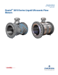





![[U4.34.03] Opérateur DEFI_LIST_INST](http://vs1.manualzilla.com/store/data/006386380_1-cfb0e6051aa46a9643ad50d1ac8d05ae-150x150.png)