1
OPERATION
AND
SERVICE
MANUAL
11971 SERIES
,
Ir
I
I
1-i.AR~.IIONIC ~-~IXERS
CERTIFICATION
Hewlett-Packard Company certifies that this product met its published specifications at the time of
shipment from the factory. Hewlett-Packard further certifies that its calibration measurements are
traceable to the United States National Bureau of Standards, to the extent allowed by the Bureau :S
caiibration facility, and to the calibration facilities of other International Standards Organization
members.
WARRANTY
This Hewlett-Packard instrument product is warranted against defects in material and workmanship
for a period of one year from date of shipment. During the warranty period, Hewlett-Packard Company will, at its option, either repair or replace products which prove to be defective.
For warranty service or repair, this product must be returned to a service facility designated by HP.
Buyer shall prepay shipping charges to HP and HP shall pay shipping charges to return the product to
Buyer. However, Buyer shall pay all shipping charges, duties, and taxes for products returned to HP
from another country.
HP warrants that its software and firmware designated by HP for use with an instrument will execute
its programming instructions when properly installed on that instrument. HP does not warrant that the
operation of the instrument, or software, or firmware will be uninterrupted or error free.
LIMITATION OF WARRANTY
The foregoing wa.rra.11ty sh::~H not apply to defects resulti'lg from improper or inadequate maintenance
by Buyer, Buyer-supplied software or interfacing, unauthorized modification or misuse, operation
outside of the environments~l specifications for the product; or improper site preparation or maintenance.
NO OTHER WARRANTY IS EXPRESSED OR IMPLIED. HP SPECIFICALLY DISCLAIMS THE IMPLIED WARRANTIES OF MERCHANTABILITY AND FITNESS FOR A PARTICULAR PURPOSE.
EXCLUSIVE REMEDIES
THE REMEDIES PROVIDED HEREIN ARE BUYER'S SOLE AND EXCLUSIVE REMEDIES. HP
SHALL NOT BE LIABLE FOR ANY DIRECT, INDIRECT, SPECIAL, INCIDENTAL, OR CONSEQUENTIAL DAMAGES, WHETHER BASED ON CONTRACT, TORT, OR ANY OTHER LEGAL
THEORY.
ASSISTANCE
Product maintenance agreements and other customer assistance agreements are available for HewlettPackard products.
For any assistance, contact your nearest Hewlett-Packard Sales and Service Office. Addresses are
provided at the back of this manual.
_______ Ffj0W
HEWLETT _ _ _______,
-=~PACKARD
OPERATION AND SERVICE MANUAL
11971 SERIES
HARMONIC MIXERS
(K, A, Q, U, and V Models)
SERIAL NUMBERS
This manual applies directly t::> HP 11971K and A mixers
with serial numbers prefixed 2332A, to HP 11971Q mixers with serial numbers prefixed 2525A, and to HP
11971U and V mixers with serial numbers prefixed
2526A.
For additional important information about serial
numbers, see MIXERS COVERED BY MANUAL in
Section!.
COPYRIGHT© 1985, HEWLElT·PACKARD COMPANY
1212 VALLEY HOUSE DRIVE, ROHNERT PARK, CALIFORNIA, 94928-4999, U.S.A.
MANUAL PART NUMBER: 11971 ..90014
Microfiche Part Number: 11971·90015
Printed: August 1985
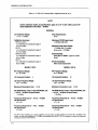
CONTENTS
GENERAL INFORMATION . . . . . . . . . . . . . .
Introduction . . . . . . . . . . . . . . . . . . . . . . . . .
Mixers Covered by Manual . . . . . . . . . . . . . . . .
Serial Numbers . . . . . . . . . . . . . . . . . . . . . .
~1anual
1-1
1-1
1-1
1-1
Measurements with the HP 11971 Mixers ......
Basic Frequency Measurement . . . . . . . . . . . . .
Identifying Signals with the HP 8569B ........
Signal Analyzer Signal Identifier . . . . . . . . . .
Image Frequency Method . . . . . . . . . . . . . . .
Amplitude Calibrated Measurements . . . . . . . . .
UpdatL90J.g Supplement . . . . . . . . . . . . 1-1
Options . . . . . . . . . . . . . . . . . . . . . . . . . . . . 1-2
2-3
2-3
2·3
2-3
2-4
2-6
Spectrum Analyzer High Power LO Options . . . . 1-3
Specifications . . . . . . . . . . . . . . . . . . . . . . . . 1-4
III PERFORMANCE TESTS . . . . . . . . . . . . . . . . . 3-1
Equipment Supplied . . . . . . . . . . . . . . . . . . . . 14
Waveguide Connector Screws . . . . . . . . . . . . 1-4
Test Record . . . . . . . . . . . . . . . . . . . . . . . . . . 3-1
Test Equipment and Accessories Available ...... 1-4
Environmental limitations . . . . . . . . . . . . . . . . 1-4
II
ii
OPERATION . . . . . . . . . . . . . . . . . . . . . . . . .
Introduction . . . . . . . . . . . . . . . . . . . . . . . . .
Operating Precautions . . . . . . . . . . . . . . . . . . .
RF Input Power . . . . . . . . . . . . . . . . . . . . .
LO Input Power . . . . . . . . . . . . . . . . . . . . .
Electrostatic Discharge . . . . . . . . . . . . . . . .
HP 11975A ALC Switch . . . . . . . . . . . . . . .
Waveguide Protection Foam . . . . . . . . . . . . .
Getting Started . . . . . . . . . . . . . . . . . . . . . . .
2-1
2-1
2-1
2-1
2-1
2-1
2-1
2-1
2-2
Conversion Loss and Frequency Response ...... 3-7
Average Noise Level Test . . . . . . . . . . . . . . . . 3-15
IV SPECTRUM ANALYZER CALIBRATION ..... 4-1
Introduction . . . . . . . . . . . . . . . . . . . . . . . . . 4-1
V
SERVICE . . . . . . . . . . . . . . . . . . . . . . . . . . .
Maintenance . . . . . . . . . . . . . . . . . . . . . . . . .
Repairs . . . . . . . . . . . . . . . . . . . . . . . . . . . . .
Replaceable Parts . . . . . . . . . . . . . . . . . . . . . .
Replacement of SMA Connectors . . . . . . . . . . .
Circuit Description . . . . . . . . . . . . . . . . . . . . .
5-1
5-1
5-1
5-1
5-1
S-1
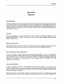
GENERAL INFORMATION
SECTION I
GENERAL INFORMATION
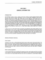
INTRODUCTION
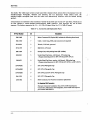
The HP Models 11 9 7 1K, 11 9 7 1A, 11 9 7 1Q, 11 9 71 U and 11 9 71 V are general-purpose harmonic mixers
with very flat frequency response characteristics and low conversion loss. Collectively, they cover the
frequency range of 18 to 7 5 GHz. The 11971K covers 18 to 26. 5 GHz, the 11971 A covers 26. 5 to 40
GHz, the 11971Q covers 33 to 50 GHz, the 11971 U covers 40 to 60 GHz and the 11971V covers 50 to
7 5 GHz. The overall local oscillator (LO) frequency range of the HP 11971 Series Mixers is 2. 0 to 4. 5
GHz. Each model in the series employs a different LO harmonic, and as a result has a different LO range
within the overall range of the series. The LO ranges of these mixers make them fully compatible with
the HP Model 8 56 9B Spectrum Analyzer. The HP 119 71 Mixers use the HP Model 11 9 7 SA Amplifier to
raise the LO power to their required LO power level of + 14 to + 18 dBm. By taking advantage of the
power leveling capability of the HP 11975A. The mixers are able to achieve maximum measurement
accuracy at their optimum LO input level of + 16 dBm. (See also Signal Analyzer High Power LO Options
below.)
A label on the top of each mixer shows a Conversion Loss Calibration graph plotted especially for that
particular mixer. An 8-1/2 by 11-inch calibration table shipped with the mixer provides a larger, easier
to read version of the same graph shown on the label, plus a list which shows the conversion loss and
reference level offset at significant points across the mixer's frequency range. The calibration table,
accurate to ±2 dB, can be employed for absolute amplitude measurements. Also supplied with each mixer
are five screws (four required) for attaching the mixer RF input flange to the waveguide.
MIXERS COVERED BY MANUAL
Serial Numbers
Attached to your mixer is a label which shows both the mixer model number and its serial number. The
serial number is in two parts. The first four digits and the letter are the serial number prefix; the last five
digits are the suffix. The prefix is the same for all identical mixers; it changes only when a change is
made to the mixer. The suffix, however, is assigned sequentially and is different for each mixer. The
contents of this manual apply to mixers with the serial number prefixes listed under SERIAL NUMBERS
on the title page.
Manual Updating Supplement
A mixer manufactured after the printing of this manual may have a serial number prefix that is not listed
on the title page. This unlisted serial number prefix indicates the mixer is different from those described
in this manual. The manual shipped with this newer mixer is accompanied by a yellow Manual Updating
1-1
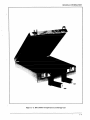
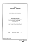
GENERAL INFORMATION
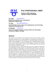
HP 11971K
HP 11971A
WAVEGUIDE SCREWS
HP PART NUMBER 3030-0221
HP 119710
HP 11971U
HP 11971V
WAVEGUIDE SCREWS
HP PART NUMBER 1390-0671
Figure 1-1. HP 11971 Series Harmonic Mixers
supplement. This supplement contains change information which explains how to adapt the manual to the
newer mixer.,
In addition to change information, the supplement may contain information for correcting errors in the
manual. To keep this manual as current and accurate as possible, Hewlett-Packard recommends that you
periodically request the latest Manual Updating supplement. The supplement for this manual is identified
with this manual's print date and part number, both of which appear on the manual title page.
Complementary copies of the supplement are available from your nearest Hewlett-Packard office.
Addresses of major offices worldwide are listed on the inside rear cover of this manual.
For information concerning a serial number prefix that is not listed on the title page or in the Manual
Updating supplement, contact your nearest Hewlett-Packard office.
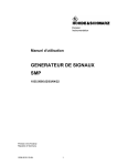
OPTIONS
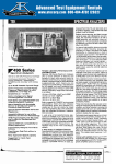
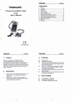
Option 009, shown in Figure 1-2, is a Mixer Connection Kit. It includes three low-loss SMA cables (HP
Part Number 5061-5458), one hex-head ball-driver (HP Part Number 8710-1539) for tightening the
waveguide connector screws, and one . 312-inch open-end wrench (HP Part Number 8710-051 0) for use
on the SMA connectors.
1-2
GENERAL INFORMATION
LOW-LOSS SMA CABLE (1 OF 3)
HP PART NUMBER 5061-5458
/
OOIIIt&'f
5/16-INCH OPEN-END WRENCH
HP PART NUMBER 8710-0510
_,~
......
Figure 1-2. Mixer Connection Kit; Option 009
SPECTRUM ANALYZER HIGH POWER LO OPTIONS
Option 003 for the HP Model 8569B Spectrum Analyzer adds an internal amplifier to the analyzer's LO
output. With this optional amplifier, the analyzer's LO output power level is increased to meet the LO
input power requiren1ent of the mixers, and the HP Model 11975.A.. l*·.,mplifier (or its equivalent) normally
used for this purpose can be eliminated from the test setup.
1-3
GENERAL INFORMATION
Option 013 for the HP 85698 adds an internal amplifier to the analyzer's LO output and also provides the
analyzer with an internal comb generator. As with Option 003, Option 013 eliminates the need for an
external amplifier to increase the analyzer's LO output power to the level required by the mixer.
For further information about HP 85698 Option 003 and its installation, refer to HP Service Note
85698-2. Option 013 is described in HP Service Note 85698-3.
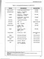
SPECIFICATIONS
Specifications for the HP Model 11971 Series Mixers are listed in Table 1-1. These are the performance
standards against which the mixers are tested (performance tests are provided in Section III). Typical or
nominal operating values are listed in Table 1-2, Supplemental Characteristics. Supplemental
characteristics are included only as additional information; they are not specifications.
EQUIPMENT SUPPLIED
Waveguide Connector Screws
Five hex-head screws (includes one spare), HP Part Number 3030-0221 or1390- 0671, are supplied with
each mixer. Use ONLY the screws supplied with it to attach the mixer to the waveguide. The special
ball-driver hex screwdriver available in the Option 009 Mixer Connection Kit simplifies installation of
the waveguide screws.
TEST EQUIPMENT AND ACCESSORIES AVAILABLE
Equipment and accessories recommended for testing the Model 11971 Series Mixers are listed in Section
III.
The HP 11969A is a wooden, internally padded, transportation and storage case (HP Part Number
5061- 5459). See Figure 1-3. This case will hold as many as five different mixers and a Mixer Connection
Kit.
ENVIRONMENTAL LIMITATIONS
The HP 11971 Series Mixers meet or exceed the environmental requirements of MIL-T-28800C, Type III,
Class 3, Style C. Their specific environmental qualifications are as follows:
Temperature, Non-operating: -40 °C to + 7 5 °C
Temperature, Operating: 0 °C to +55 ° C
Relative Humidity: 95 ±5% up to 30°C
Altitude, Non -operating: Less than 12,19 5 meters ( 40,000 ft.)
Altitude, Operating: Less than 3,048 meters ( 10,000 ft.)
Maximum Vibration Levels: 2 G's at 5 Hz to 2000 Hz
Maximum Shock.: 30 G's
1-4
GENERAL INFORMATION
J
Figure 1-3. HP ll969A Transportation and Storage Case
l-5
GENERAL lNFORMATION
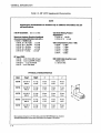
Table 1-1. HP 11971 Series Mixer Specifications (1 of 2)
NOTE
Unless otherwise stated, all specifications apply for an IF of 321.4 MHz and for RF
input amplitudes of less than -20 dBm.
GENERAL
LO Ampiiiude Range:
1
+14to +18dBm
Bias Requirements:
None
Calibration Accuracy:
11971K/A/Q/U:
± 2.0 dB with LO amplitude range of
14.5 to 16 dBm
11971V:
± 2.2 dB with LO amplitude range of
14.5 to 16 dBm
11971K/A/Q/U:
± 3.0 dB with LO amplitude range of
16to 18dBm
11971V:
± 3.2 dB with LO amplitude range of
16to 18dBm
Maximum CW RF Input Level:
+20dBm (100 mW)
Maximum Peak Pulse Power:
+ 24 dBm with <I ,.,s pulse
(avg. power: + 20 dBm)
Environmental:
Meets MIL-T-28800C, Type III, Class 3,
StyleC
IF/LO Connectors:
SMA female (replaceable)
MODEL 11971K
MODEL 11971A
RF Frequency Range:
RF Frequency Range:
26.5-40GHz
18-26.5GHz
LO Harmonic Number:
6
LO Harmonic Number:
LO Input Frequency Range:
2.62-3.97 GHz
LO Input Frequency Range:
2.95- 4.36 GHz
Maximum Conversion Loss:
10
24 dB
Maximum Conversion Loss:
28 dB
HP 8569B Noise Level at 1 kHz Bandwidth, and
+ 14.5 to + 16 dBm LO Input Power:
-llOdBm
HP 8569B Noise Level at 1 kHz Bandwidth, and
+ 14.5 to + 16 dBm LO Input Power:
-106dBm
Frequency Response at + 14.5 to + 16 dBm
LO Input Power:
±2.1 dB
Frequency Response at + 14.5 to + 16 dBm
LO Input Power:
±2.1 dB
Frequency Response at + 14 to + 18 dBm
LO Input Power:
±3.0dB
Frequency Response at
LO Input Power:
±3.0dB
+ 14 to + 18 dBm
'The HP 11975A Amplifier, or a similar amplifier, must be used to provide sufficient LO power (14 to 18 dBm) to the
mixers. Leveled power capability of+ 16 dBm, as is available with the HP 11975A, is necessary to achieve the maximum
a.tnplitude accuracy with the mixers.
1-6
GENERAL INFORMATION
Table 1-1. HP 11971 Series Mixer Specifications (2 of 2)
MODEL 11971Q
MODEL 11971U
RF Frequency Range:
33-50GHz
LO Harmonic Number:
RF Frequency Range:
40-60GHz
LO Harmonic Number:
16
LO Input Frequency Range:
2.04-3.10GHz
Maximum Conversion Loss:
16
LO Input Frequency Range:
2.48-3.73 GHz
40 dB
Maximum Conversion Loss:
40 dB
H P 8569B Noise Level at 1 kHz Bandwidth, and
+ 14.5 to + 16 dBm LO Input Power:
-92dBm
HP 8569B Noise Level at 1 kHz Bandwidth, and
+ 14.5 to + 16 dBm LO Input Power:
-92 dBm
Frequency Response at + 14.5 to + 16 dBm
LO Input Power:
±2.3dB
Frequency Response at + 14.5 to + 16 dBm
LOinputPower:
±2.3dB
Frequency Response at + 14 to + 18 dBm
LO Input Power:
±3.2dB
Frequency Response at
LO Input Power:
±3.2dB
+ 14 to + 18 dBm
MODEL 11971V
RF Frequency Range:
50-750Hz1
LO Harmonic Number:
16
LO Input Frequency Range:
3.10-4.42 GHz
Maximum Conversion Loss:
42 dB
HP 8569B Noise Level at 1kHz Bandwidth, and
+ i 4.5 to + i 6 dBm LO input Power:
-89dBm
Frequency Response at
LO Input Power:
±2.5dB
+ 14.5 to + 16 dBm
Frequency Response at + 14 to + 18 dBm
LO Input Power:
±3.2dB
'The maximum frequency is 71 GHz when used with the HP 8569B Spectrum Analyzer.
1-7
GENERAL INFORMATION
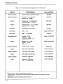
Table 1-2. HP 11971 Supplemental Characteristics
NOTE
Supplemental characteristics are included only as additional information; they are
not specific-ations.
DC to 1.3 GHz
3 dB IF Bandwidth:
Odd Order Mixing Product
Suppression:
Spectrum Analyzer Absolute Amplitude
Accuracy (using calibration data with a
+ 14.5 to + 16 dBm LO):
11971K/A: >20 dB
11971Q/U/V: >15 dB
11971K, 18-26.5 GHz: ±3.3dB
11971A, 26.5-40 GHz: ±3.3dB
11971Q, 33-50GHz:
±3.3dB
11971U, 40-60 GHz:
±3.3dB
1i9i1V, 50-75 GHz:
±3.4dB!
Gain Compression Level (<1 dB):
11971K: -3 dBm
11971A: -7 dBm
11971Q: -3 dBm
H9iiU: -3 dBm
11971V: -3 dBm
RF Input SWR:
11971K: <2.9:1 First 200/o of band
ll971K: <2.2:1 Last 800/o of band
ii97iQ/U: <2.2:1 Fuii band
ll971V: <2.6:1 Full band
5061·5458 Cable Insertion Loss:
.8dBat2GHz
l.i dB at 6 GHz
PHYSICAL CHARACTERISTICS
Model
Flange2
. ....
J- u;
'1:0'1: IJ T
.......=~_,..,,-
110711(
·~·
f)
17 Jr ..
'""'• ... f
'""et
X
y
z
...,..., ..........
,., ... ••u••
oo .......
..,..,
......
WR-42
0.36lb
1.4 in
2.0in
3.5 in
11971A
UG-599/U
WR-28
0.14 kg
0.321b
36rnm
1.4in
51 mrn
2.0in
7lmm
2.8in
111:17-tn
Tlr!
vu-.;Jo~/v
u • .&.,I\.Q
1\ 1 A L.-
"1&.-.;JU .lUlU
l:f--
..JJ. 1&1111
"''L--
WR-22
0.321b
1.4 in
2.0in
3.0in
11971U
UG-383/U-M
WR-19
0.14 kg
0.32lb
36rnm
1.4 in
Slmm
2.0in
76mm
3.0in
11971V
UG-385/U
WR-12
0.14 kg
0.32lb
36mm
1.4in
51 mrn
2.0in
76mrn
3.0in
I 1.::1'1 IU.
1
Weight
~O"'nT
1\1111111
The maximum frequency is 71 GHz when used with HP 8569B Spectrum Analyzer.
Waveguide attachment screws enter blind holes in the flanges of the mixers.
2
1-8
OPERATION
SECTION II
OPERATION
INTRODUCTION
Tl1is section provides information on how to make effective use of the HP 119711Yfixers.
OPERATING PRECAUTIONS
Do not exceed the maximum ratings listed below or permanent damage to the mixer will result.
RF Input Power
CW: No greater than + 20 dBm
Pulse: No greater than +24 dBm at~ l USee
Average: No greater than +20 dBm
LO Input Power
No greater than +20 dBm
EJectrostatic Discharge
When installing the mixer, always connect the SMA cables to the spectrum analyzer and LO amplifier
BEFORE connecting them to the mixer. This will minimize the danger of an electrostatic discharge
damaging the mixer diodes.
HP !197SA ALC Switch
BEFORE using the HP 1197 SA Amplifier to increase the LO input power, set the amplifier ALC switch
to the ON position. When this switch is in the OFF position the LO power can be greater than +20 dBm.
This level of LO power can destroy the mixer diodes. The ALC switch is on the amplifier rear panel.
Waveguide Protection Foam
Do not remove, displace, or damage the white, non-conductive foam installed in the open end of the
waveguide. Since the mixer is amplitude calibrated with this foam in place, tampering with it affects the
calibration.
2-1
OPERATION
GETTING STARTED
NOTE
See Section I for information relating to High Power LO options for HP
Model 8569B Spectrum Analyzers.
The HP Model 11971 series of millimeter wave mixers have no bias or back-short adjustments.
HP 11971 Mixers require an LO power of + 14 to + 18 dBm at the LO input. If the analyzer you use with
the HP 11971 Mixer does not have sufficient LO power, use the HP 1197 SA Amplifier or an equivalent
to increase the LO power.
CAUTION
Before connecting the HP 11975A Amplifier, set its rear panel ALC
switch to ON. Failure to do this wiJI damage the mixer.
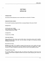
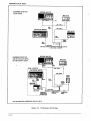
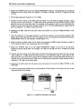
With the three SMA cables (HP Part Number S061-S4S8) provided in the Option 009 Mixer Connection
Kit, connect the HP 11971 Mixer, the spectrum analyzer, and the HP 1197 SA Amplifier as shown in
Figure 2-1.
Leave the waveguide cap on whenever the mixer is not connected to a device under test. This protects the
flange mating surface from dust and scratches, which can degrade the mixer's performance. Use an
appropriate waveguide attenuator if the output power of the unit under test exceeds the Maximum RF
Input Power shown in the specifications.
SPECTRUM ANALYZER
SMA CABLES
SMA CABLE
Figure 2-1. HP 11971 Mixer Connections
2-2
OPERATION
MEASUREMENTS WITH THE HP 11971 MIXERS
The control settings used in this section are for the HP 8569B Spectrum Analyzer for two reasons: First,
the HP 8569B IF input requires a 321.4 MHz signal, and this is compatible with the IF calibration
frequency of the HP 11971 Mixers. This output, specifically designed for a 321.4 MHz IF, is coupled
through a 1. 5 GHz low-pass filter. Second, the frequency range of the HP 8569B 1st LO output is
between 2. 5 and 4. 5 GHz, which fulfills the LO input frequency requirements of the HP 11971.
BASIC FREQUENCY MEASUREMENT
Set the controls on the HP 8569B as follows:
1. Push in all green pushbuttons except MIXING MODE [!NT] and FREQUENCY SPAN MODE [PER
DIV]. (See Normal Settings in the HP 8569B Spectrum Analyzer Operation manual.) Set VIDEO
FILTER to OFF (green position), SWEEP TIME/DIY to AUTO (green position), and line up the green
arrows on the FREQUENCY SPAN/DIY and RESOLUTION BW controls.
2. Pres8 MIXINGMODE [EXT].
3. Press the FREQUENCY BAND GHz pushbutton corresponding to the mixer's frequency band.
4. Set the FREQUENCY SPAN MODE to [FULL BAND].
5. Set the FREQUENCY SPAN/DIY control to l 00 MHz.
6. Set the INPUT A TTEN (dB) control to 0.
7. Set REFERENCE LEVEL to -10 dBm and FINE to 0 dB.
8. Set EXT MIXING BIAS in detent positon (center). This turns off the mixing bias. It is not required for
HP 11971 Mixers.
When using an external mixer, set the spectrum analyzer internal attenuator to 0 dB to maintain the
correct reference level. Except for this internal attenuator control of the reference level, operation of the
HP 8569B in the external mixing mode is identical with the standard operation described in the HP
8569B Spectrum Analyzer Operation Manual.
If the frequency of the signal is known, rotate the FREQUENCY TUNING control until the frequency is
shown on the digital display. For a more detailed analysis of the signal, set the HP 8569B to the PER DIY
mode and rotate the FREQUENCY SPAN knob to obtain the desired resolution.
IDENTIFYING SIGNALS WITH THE HP 8569B
Signal Analyzer Signal Identifier
The built-in signal identifier can be used to verify that the displayed response is the desired signal. For
this verification, set the SPA~.J/DIV control to 2 ~,1Hz/DIV. Center the iesponse on the display, then press
SIG IDENT. If the response is correct, a second signal, shifted one division to the left, appears on the
display. (See Figure 2-2.)
2-3
OPERATION
Signals with residual FM, or FM pulse modulation, might not be successfully identified with the Signal
Identification routine. If you are in doubt about the identification, use the .,image frequency method.. of
signal identification described below.
YFOFF
CTR 24. 015 GHz
SPAN 2 MHzl
RES BV 100 kHz
REF -20 !&
10 <II/
ATTEN 0 dB
SVP AUTO
!
!
I I I I H I~ I I I I I
..
2MHz
.JJI
\ir.J.,
..II.
•.A.
Figure 2-2. Signal Identifier
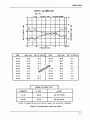
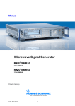
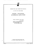
Image Frequency Method
The "image frequency method" of signal identification depends on the fact that the correct response has
an image that is displayed 643 MHz (twice the 321. 4 MHz IF) above it on the spectrum analyzer CRT.
Knowledge of the harmonic mixing process makes the "image frequency method" easier and faster to use.
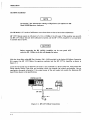
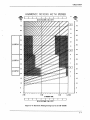
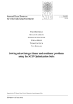
Figure 2-3 shows a typical display on the HP 8569B with a 24 GHz signal applied to the HP 11971K
Mixer. A reduced version of the HP 8569B Spectrum Analyzer harmonic mixing tuning curves (shown in
Figures 2-4 and 2-5) is included in Figure 2-3 to aid in identifying the signals present on the display. HP
11971K Mixers are factory-calibrated for the 6+ mixing mode, which gives them a corresponding LO
frequency range of 2. 95 to 4. 36 GHz. By reference to the tuning curves in Figures 2-4 and 2-5, it can be
determined that the signals displayed in approximately the first four divisions of the display are the result
of the RF mi'{ing with LO frequencies of less than 3 GHz. Because these signals are obviously not the
desired responses, there is no need to investigate them further. The large response pair near the fourth
division of the CRT can be seen to be the result of the RF input mixing with the 8th harmonic of the LO.
The desired 6+ harmonic response is the large response pair near the 8th division of the CRT.
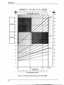
The shaded areas on the chart in Figures 2-4 and 2-5 represent the regions for each HP 11971 Series
r-. .1ixer where the responses are imprecise, a result of the P"F mixing with LO frequencies outside the LO
range of the mixer. Any signal falling inside a shaded area can be ignored.
1. To begin the identification procedure, set the HP 8569B controls as described in Basic Frequency
Measurement paragraph.
2. Using the chart in Figures 2-4 or 2-5, determine the limits on the display within which the desired
image pair can appear.
3. Rotate the HP 8569B TUNING control to place the marker between a pair of possibly correct
responses.
2-4
OPERATION
HARMONIC MIXING WITH 85698
IIIIIT
AliiiEia
Iiiii)
lU
115
Ill
13
!5
IZ
ill
II
45
11971A
4D
<!!!
IS
IS
..
ill
15
15
lD
lD
15
15
11971K
IG
Figure 2-3. Harmonic Mixing Curves for Signal ID
4. Set the spectrum analyzer to the per division mode by pressing the FREQUENCY SPAN MODE [PER
DIV) pushbutton.
5. If the separation between the pair of responses is 6. 4 divisions (that is1 643 MHz) on the display, you
have located the desired pair. Of the two responses, the correct mixing product is always the one on
the left, and the right-hand response is its image. In general, if the separation is less than 6. 4 divisions,
the desired pair of responses is lower in frequency than the observed pair.
2-5
OPERATION
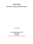
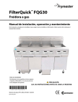
AMPLITUDE CALIBRATED MEASUREMENTS
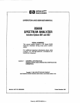
~,The HP 8569B Spectrum Analyzer can make amplitude calibrated measurements of millimeter signals
,. -with the HP 11971 Mixers. A calibration table like the one shown in Figure 2-6 is provided with each
. mixer. A smaller version of the graph shown on the table is on the mixer itself. The table shows
-: conversion loss and a correction factor to bt: added to the display reading as a function of frequency. The
: graph shows two plots: Mixer Conversion Loss, and ADD TO DISPLAY amplitude correction data for use
' with the HP 8569B Spectrum Analyzer.
In the external m1xmg mode, the H.t' 8569B gain is automatically increased to compensate for the
conversion loss of the HP 11971 Mixer. Each external mixing band has two adjustments available on the
HP 85698. The OFFSET adjustment compensates for the average conversion loss and the ;;SLOPE;;
adjustment compensates for the average variation over the band.
The calibration table contains the data required to calibrate the HP 85698 for use with its associated
mixer. This information is repeated on the labels on the mixer body. The procedure for calibrating the HP
85698 for a particular HP 11971 Mixer is provided in Seeton IV.
Obtaining an amplitude calibrated measurement using the HP 11971 Mixer with the HP 85698 is simple.
To the signal amplitude display on the CRT a correction factor must be added. The correction factor is
the ADD TO DISPLAY data shown in the calibration table and plotted on the graph on the mixer label.
For example, referring to the table in Figure 2-6, if the displayed signal is -21 dBm at 22 GHz, and the
ADD TO DISPLAY (ATD) is -0.5 d8m, the correct amplitude is -21. 5 dBm.
NOTE
For the REFERENCE LEVEL to function properly, the INPUT
ATTENUATOR must be set to 0 dB. Additionally, for proper operation of
the HP 11971 Mixers, the EXT MIXING BIAS control must be set to the
detent position.
2-6
OPERATION
HARMONIC MIXING WITH 85698
DFUT
~
~I--~--~--~~--~--~--~--~--4-~
GiHz)
75
N
III'UT
FllfJIEII:Y
OiHz)
DIVISIONS ON CRT
i5
70
70
15
65
65
14
Ill
13
55
12
11971U
!il
91
11
45
g
t - - - - - 1 40
8
11971A
I
I~
7
I~
11197U<
~-
1
I aJ
15
15
10
10
5
5
D
0
" liHz
DIVISIONS ON CRT
Figure 2-4. Harmonic Mixing Tuning Curves for HP 85698
2-7
OPERATION
HARMONIC MIXING WITH
IJIIUT
FREIIEJI:Y
(GHz)
I
85698
N
I
<GHz)
DIVISIONS ON CRT
75
IIFUT
FliBIBI:Y
75
[!!]
70
70
15
65
ll971V
65
14
110
110
13
55
12
50
!ill
11
45
~
40
9
35
8
1197HJ
35
7
[I]
25
25
5
20
4
15
15
10
w
5
5
0
0
4 GHz
3Gtlz
2Gtlz
4.46 GHz
LO FREIHJI:Y RAII':E
I
I
I
DIVISIONS ON CRT
I
I
Figure 2-5. Harmonic Mixing Tuning Curves for HP 8569B
2-8
OPERATION
11971K CALIBRATION
SER. NO. :
Ifa321.4 MHZ
""" 6+
LO Power•16d8m
18
I I I I I I I IJ
41
·FI/\ J7\I_
I I II II II II ~];q1I I
iii
!!
•>~
·r ~I ~
M
0
0
~
0
~·rT\/1
c-«
4
se
18
iii
~
rn
rn
20
0
.J
z
0
M
rn
22
a:
&u
>
z
0
(J
I I I
20
22
I
24
I
II
28.5 24
FREQUENCY (GHz)
FREQ.
CONV LOSS
FREQ.
ADD TO DISPLAY
CONV.LOSS
ADD TO DISPLAY
18.00
21.8
-0.2
22.50
20.5
-0.7
18.50
21.9
0.2
23.00
20.7
-0.4
19.00
21.8
-0.0
,~
20.4
-0.7
19.50
22.3
0.7
. ~®
20.3
-0.7
20.00
21.8
20.9
-0.1
20.50
21.5
25.oo
21.1
0.2
21.00
21.2
25.50
21.5
0.7
21.50
21.2
-0.2
26.00
21.5
0.8
22.00
20.8
-0.5
26.50
21.2
0.5
o.~ ~~ .~.so
§®
I
FREQUENCY
1
I
85698 CALIBRATION*
IF GAIN
I
ADJUST
12.40
22.50
A20 87A OFFSET
26.50
20.70
A20 878 SLOPE
*REFER TO 85698 OPERATION AND SERVICE MANUAl FOR ADJUSTMENT PROCEDURE
Figu-re 2-6. Sample Mixer Calib-ration Table
2-9
OPERATION
2-10
'lltlll _ _ _ _ _ _ _ _ _ _ _ _ _ _ _ _ __
PERFORMANCE TESTS
SECTION Ill
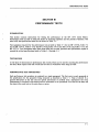
PERFORMANCE TESTS
INTRODUCTION
This section contains instructions for testing the performance of the HP 11971 Series Mixers.
Performance tests are used to check the mixers at incoming inspection and for periodic evaluation. The
tests verify the specifications listed for the mixers in Table 1-1.
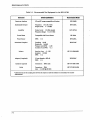
Test equipment required for the performance tests is listed in Table 3-i for the HP i 197iK, Table ~-.~.
for the HP 1197 lA, Table 3-3 for the HP 11971Q, Table 3-4 for the HP 11971 U and Table 3-5 for the
HP i i 971 V. Test instruments other than those listed may be used, provided their performance equais or
exceeds the critical specifications listed in Tables 3-1 through 3-5.
TEST RECORD
At the back of this section are performance test records, which can be used for recording the performance
test data. Make copies of the test records and use them as worksheets when doing the tests.
PERFORMANCE TEST PROCEDURES
Each performance test procedure is contained in a single paragraph. The first entry in each paragraph is
the specification for the parameter being measured as described in Table 1-l. This is followed by a
general description of the test and any special instructions or problem areas. Appropriate test setup
illustrations are included in this section and are referenced in the procedures. You must do the tests, and
the steps within each test, in the order they are given.
3-1
PERFORMANCE TESTS
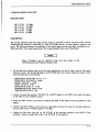
Table 3-1. Recommended Test Equipment for the HP 11971K
Instrument
Critical Specifications
Recommended Model
Spectrum Analyzer
LO and IF ranges compatible with mixer
HP8569B
Frequency: 18 to 26.5 GHz
Output Level: >- 10 dBm
HP8340A
Output Level: >18 dBm leveled
Frequency Range: 3 to 4.5 GHz
HP 11975A
Synthesized Sweeper
Amplifier
Power Meter
Compatible with Power Sensor
Power Sensor
SWR:
Directional Coupler*
Isolator
<1.3
HP436A
HP8485A
Coupling: 10 dB
Directivity: >40 dB
Primary Arm SWR: <1.05
Auxiliarv Arm SWR: <1.2
Insertion Loss:
<1.5 dB
HPK752C
HP P /N 0960-0081
Isolation: >20 dB
SWR: <1.2
Adapter (2 required)
Cables (3 required)
Cable
3.5 mm female to WR-42
SWR: <1.1
Connectors:
SMA male
Connectors: SMA
Loss: <1.0 dB @ 20 GHz
HPK281C
HP P/N 5061-5458
HP PIN 8120-4396
*Calibration data for the coupling ratio between the output arm and the auxiliary arm is necessary for accurate
measurements.
3-2
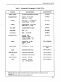
PERFORMANCE TESTS
Table 3-2. Recommended Test Equipment for the HP 11971A
Instrument
Critical Specifications
Recommended Model
Spectrum Analyzer
LO and IF ranges compatible with mixer
HP8569B
Synthesized Sweeper
Frequency: 8 to 13.5 GHz
Output Level: >0 dBm
HP8340A
Ampiifier
Ouipui Level: > + liS aJSm ieve1ea
Frequency Range: 3 to 5 GHz
HP ii975A
Amplifier
Frequency Range: 8 to 13.5 GHz
Output Level: > + 15 dBm
HP8349A
Power Meter
Compatible with Power Sensor
HP436A
Power Sensor
SWR:
<2.0
Power Sensor
SWR:
<1.3 @ 6 GHz
Directional Coupler•
Isolator
Frequency Tripier
HPR8486A
Coupling: 20 dB
Directivity: >40 dB
Primary Arm SWR: < 1.05
Auxiliary Arm SWR: < 1.2
Insertion Loss: <1.5 dB
Isolation: >20 dB
SWR: <1.2
Conversion Loss:
<15 dB
HP8485A
HPR752D
HP PIN 0960-0082
Spacekom Microwavel
TKa-1
Adapter
SMA female to SMA female
HP P/N 1250-1158
Adapter (2 required)
Type N male to SMA female
HP P/N 1250-1250
SMA female to Type N female
HP P/N 1250-1404
Connectors:
HP P/N 5061-5458
Adapter
Cables {4 required)
Cable
SMA male
Connectors: SMA male
Loss: <1.0 dB @ 20 GHz
HP PIN 8120-4396
1Calibration
data for the coupling ratio between the output arm and the auxiliary arm is necessary for accurate
measurements.
2Honeywell, Inc. Spacekom Microwave Center, Santa Barbara, CA
3-3
PERFORMANCE TESTS
Table 3-3. Recommended Test Equipment for the HP 11971Q
Instrument
CriticaiSpecrncations
Recommended Model
Spectrum Analyzer
LO and IF ranges compatible with mixer
HP8569B
Frequency: 11.0 to 16.7 GHz
Output Level: >0 dBm
HP8340A
Output Level: > + ! 8 dBm leveled
Frequency Range: 3 to 5 GHz
HP 1!975A
Frequency Range: 11.0 to 16.7 GHz
Output Level: >+ 15 dBm
HP8349A
Power Meter
Compatible with Power Sensor
HP436A
Power Sensor
SWR:
<2.0
Power Sensor
SWR:
<1.3@ 6 GHz
Synthesized Sweeper
Amplifier
Directional Coupler•
Isolator
Frequency Tripier
HPQ8486A
HP8485A
Coupling: 20 dB
Directivity: >30 dB
SWR: <1.2
HPQ752D
Insertion Loss: <2.0 dB
Isolation: >20 dB
SWR: <1.5
HPQ365A
Conversion Loss:
<20 dB
Spacekom Microwave2
TB-1
Adapter
SMA female to SMA female
HP P/N 1250-1158
Adapter (2 required)
Type N male to SMA female
HP P/N 1250-1250
SMA female to Type N female
HP P/N 1250-1404
Connectors:
HP P/N 5061-5458
Adapter
Cables (4 required)
Cable
SMA male
Connectors: SMA male
Loss: <l.OdB @200Hz
HP P/N 8120-4396
•calibration data for the coupling ratio between the output arm and the auxiliary arm is necessary for accurate
measurements.
2 Honeywe!!,
3-4
Inc. Spacekom Microwave Center, Santa Barbara, CA
r
I
PERFORMANCE TESTS
Table 3-4. Recommended Test Equipment for the HP 11971U
Instrument
Critical Specifications
Recommended Model
Spectrum Analyzer
LO and IF ranges compatible with mixer
HP8569B
Synthesized Sweeper
Frequency: 13.3 to 20.0 GHz
Output Level: >0 dBm
HP8340A
Amplifier
Output Level: >+ 18 dBm leveled
Frequency Range: 3 to 5 GHz
HP 11975A
Amplifier
Frequency Range: 13.3 to 20.0 GHz
Output Level: >+ 15 dBm
HP8349A
Power Meter
Compatible with Power Sensor
HP432A
Power Sensor
SWR:
<2.0
Hughes 1 45773H-1100
Power Sensor
SWR: <1.3@ 6GHz
HP478A
Directional Coupler2
Isolator
Coupling: 20 dB
Directivity: >30 dB
SWR: <1.2
HPU752D
Insertion Loss: <1.5 dB
Isolation: >20 dB
SWR: <1.2
HPU365A
Frequency Tripier
Conversion Loss: <20 dB
Spacekom Microwavel
TQ-1
Adapter
SMA female to SMA female
HP PIN 1250-1158
Adapter (2 required)
Type N male to SMA female
HP PIN 1250-1250
SMA female to Type N female
HP PIN 1250-1404
Adapter
Cables (4 required)
Cable
Connectors:
SMA male
Connectors: SMA male
Loss: <1.0 dB @ 20 GHz
HP PIN 5061-5458
HP PIN 8120-4396
1
Hughes Aircraft Co. Electron Dynamics Division, Torrance, CA
Calibration data for the coupling ratio between the output arm and the auxiliary arm is necessary for accurate
measurements.
3
Honeywell, Inc. Spacekom Microwave Center, Santa Barbara, CA
2
3-5
PERFORMANCE TESTS
Table 3-S. Recommended Test Equipment for the BP 11971V
Instrument
Critical Specffications
Recommended Model
Spectrum Analyzer
LO and IF ranges compatible with mixer
HP8569B
Synthesized Sweener
Freouencv: 12.5 to 18.8 GHz
Output Level: >0 dBm
HP R~ ..<tnA
-.
J
Amplifier
Output Level: >+ 18 dBm leveled
Frequency Range: 3 to 5 GHz
HP 11975A
Amplifier
Frequency Range: 12.5 to 18.8 GHz
Output Level: >+ 15 dBm
HP8349A
Power Meter
Compatible with Power Sensor
HP432A
Power Sensor
SWR:
<2.0
Power Sensor
SWR:
<1.3 @ 6 GHz
Directional Coupler2
Isolator
Frequency Quadrupler
Hughes 1 45774H-1100
Coupling: 20 dB
Directivity: >20 dB
Auxiliary Arm SWR:
HP478A
Hughes 1 45324H-1220
<1.5
Insertion Loss: <2 dB
Isolation: >20 dB
SWR: <1.5
Conversion Loss:
<25 dB
Hughes 1 45114H-1000
Spacek3 V-4X
Adapter
SMA female to SMA female
HP P/N 1250-1158
Adapter (2 required)
Type N male to SMA female
HP P/N 1250-1250
SMA female to Type N female
HP PIN 1250-1404
Connectors:
HP P/N 5061-5458
Adapter
Cables (4 required)
Cable
SMA male
Connectors: SMA male
Loss: <I.OdB@ 200Hz
HP P/N 8120-4396
Hughes Aircraft Co. Electron Dynw-rJcs Division, Torrance, CA
Calibration data for the coupling ratio between the output arm and the auxiliary arm is necessary for accurate
measurements.
lSpacek Labs Inc. MM Wave Technologies, Santa Barbara, CA
1
2
3-6
PERFORMANCE TESTS
CONVERSION LOSS AND FREQUENCY RESPONSE
SPECIFICATIONS
Conversion Loss:
For a CW input power of less than -20 dBm
HP
HP
HP
HP
HP
11971K:
11971A:
11971Q:
11971 U:
11971 V:
24 dB maximum
28 dB maximum
40 dB maximum
40 dB maximum
42 dB maximum
Frequency Response:
For an LO amplitude between + 14. 5 and + 16. 0 dBm
HP11971K:
HP 11971A:
HP 11 9 71 Q:
HP 11971 U:
HP J1971V:
±2.1dB
±2.1 dB
± 2. 3 dB
±2. 3 dB
±2. S dB
For an LO amplitude between + 14. 0 and + 18. 0 dBm
HP
HP
HP
HP
HP
11971K: ±3.0 dB
11 9 71 A: ± 3. 0 dB
11 9 71 Q: ± 3. 2 dB
11971U: ±3. 2 dB
11971V: ±3.2dB
DESCRIPTION
The frequency response and conversion loss are checked at four LO power levels. This is accomplished by
calibrating the HP 8S69B as a 321.4 MHz receiver. A known input power is applied to the input of the
mixer. The spectrum analyzer is tuned to the signal frequency and the mixer IF output power is measured
on the spectrum analyzer. From these measurements, the conversion loss and frequency response are
determined.
1. On the spectrum analyzer, push in all the green pushbuttons and set all rotary controls with green
positions to green. (See Normal Settings in the HP 8569B Spectrum Analyzer Operaton manual.) Then
make the following control settings:
FREQUENCY BAND GHz to .01--1.8
FREQUENCY SPAN/DIV to 1 MHz
RESOLUTION BW to 1 MHz
INPUT ATTEN to 10 dB
REFERENCE LEVEL to -10 dBm
REFERENCE LEVEL FINE to 0 dB
AMPLITUDE SCALE to 1 dB
3-7
PERFORMANCE TESTS
2. Connect the 100 MHz CAL OUTPUT signal to the INPUT connector, then center the signal on the
CRT display with the TUNING control.
3. Adjust the REF LEVEL CAL control to position the peak of the signal on the top graticule of the CRT
display.
4. Calibrate the HP 8569B for External Mixing as described in Section IV. Set the signal generator for an
output level of -40 dBm, instead of -10 dBm.
5. Connect an Sl\·1A cable from the 1st LO OUTPUT of the spectrum analyzer to the It..JPUT of the
amplifier. Connect a second SMA cable to the OUTPUT of the amplifier.
6. For HP 11971K: Set the Cal Factor to 100 percent, then zero and calibrate the power meter. For the
11971A, 11971Q, 11971U and 11971V: Com:iect the HP 478A Power Sensor to the power meter
sensor cables, then zero the power meter.
7. On the spectrum analyzer, push in all the green pushbuttons and set all rotary controls with green
positions to green. (See Normal Settings in the HP 8S69B Spectrum Analyzer Operationmanual.) Then
make the following control settings:
MIXING MODE to EXT
FREQUENCY SPAN MODE to ZERO SPAN
FREQUENCY BAND to:
12. 4--26. S for HP 11 971K
21--44 for HP 11971A
33--71 for HP 11971Q
33--71 forHP 11971U
3 3--71 for HP 11 9 71 V
FREQUENCY GHz TO:
22 for HP 11971K
36 for HP ll971A
4 2 for HP l 19 7 1Q
50 for HP 11 97 1U
61 for HP 11971 V
CAUiiON
When you are using an HP 11975A Amplifier with an HP 11971 Mixer,
set the amplifier rear-panel ALC switch to ON before connecting the
amplifier into the test setup. If the ALC switch is left in the OFF position,
the amplifier output power is high enough to damage the mixer diodes.
8. On the HP 1197 SA Amplifier, set the rear panel ALC switch to ON, then connect the power sensor to
the free end of the cable installed on the OUTPUT connector of the amplifier. Set the power meter
Cal Factor to the appropriate value for a frequency of 3. 5 GHz.
9. Adjust the amplifier OUTPUT POWER LEVEL for a reading of + 14. 0 ±0. 1 dBm on the power meter.
10. Connect the equipment as shown in Figure 3-1.
3-8
PERFORMANCE TESTS
I CAUTION I
Make sure the HP 8349A Amplifier, used in the signal generator system
for HP 11971A, Q, U, and V tests, is set for external leveling before you
turn it on. Failure to set this amplifier for external leveling may allow
the amplifier output to rise about +18 dBm, which is high enough to
damage the frequency tripler or quadrupler.
11. Set the signal generator for a CW output signal at the frequencies listed below:
HP
HP
HP
HP
HP
11971K:
11971A:
11971Q:
11971U:
11971V:
18.0 GHz
26.5GHz
33.0GHz
40.0 GHz
SO.OGHz
12. Adjust the output power of the signal generator for a reading of approximately -1 2 dBm on the
power meter for the HP 11971K, or -3 dBm for the HP 11971A, 11971Q, 11971U, or 11971V.
1 3. On the spectrum analyzer, push in all the green pushbuttons and set all rotary controls with green
positions to green. (See Normal Settings in the HP 8569B Spectrum Analyzer Operation manual.)
Then make the following control settings:
MIXING MODE to EXT
FREQUENCY BAND to:
12.4--26.5forHP 11971K
21--44 for HP ll971A
33--71 for HP 11971Q
33--71 for HP 11971U
33--71 for HP 11971V
FREQUENCY SPAN/DIV to 2 MHz
RESOLUTION BANDWIDTH to 1 GHz
AMPLITUDE SCALE to 2 dB/DIV
INPUT ATTEN (dB) to 0
EXTERNAL MIXING BIAS to detent position
REFERENCE LEVEL to -1 0 dBm
14. Rotate the frequency TUNING control to display the signal on the screen. Use SIG IDENT to
identify the response as a "true" signal. (If necessary, increase the frequency span/division to help
locate the true signal.) Record the signal frequency in Table 3-6.
15. Adjust the REFERENCE LEVEL controls to place the signal peak at the top graticu1e of the display.
Record the REFERENCE LEVEL control settings in Table 3-6.
3-9
PERFORMANCE TESTS
NOTE
Record the actual REFERENCE LEVEL control settings, not the REF
value shown on the CRT annotation.
16. Set the power meter CAL FACTOR to the setting corresponding to the signal frequency. Record the
power meter reading in Table 3-6. If the power meter correction factor (in dB) is available, record
that value in the table also.
17. Record the directional coupler coupling factor in Table 3-6.
NOTE
For the purposes of this measurement, the directional coupler coupling
factor is defined as the ratio of the power at the output flange to the
power at the coupled flange.
18. Calculate the conversion loss of the mixer with the following equation:
Conversion Loss = power meter reading + power meter correction
factor(dB) - directional coupler coupling factor - (spectrum analyzer
reference level - 30)
[The -30 term corrects for the fact that the top of the display is calibrated for -40 dBm when the
reference is set to -I 0 dBm, as described in Section IV.]
For example:
Power Meter Reading = -12. 58 dBm
Power Meter Correction Factor= 0. 42 dBm
Coupling Factor = 8. 9 3 dB
Reference Level= -12. 8 dBm
Conversion Loss= -12.58 + 0. 42- 8. 93 - (-12. 8 - 30) = 21.7 dBm
Record the conversion loss in Table 3-6.
NOTE
The conversion loss indicated on the mixer calibration label includes the
loss in the IF cable. If other than the specified cable is used, the Joss in
that cable must be compensated for when making amplitude
measurements.
3-10
PERFORMANCE TESTS
19. Increment the frequency of the signal generator 500 MHz higher.
20. Repeat steps 14 through 19 until the appropriate frequency listed below is reached.
I·
I
HP
HP
HP
HP
HP
11971K:
11971A:
11971Q:
11971U:
11971V:
26. 5 GHz
40.0 GHz
50.0 GHz
60.0GHz
71.0 GHz
21. Repeat steps 5 through 20 for LO inputs to the mixer of + 14. 5 dBm, + 16. 0 dBm and 18. 0 dBm. In
step 9, measure each of these levels at the end of the cable normally connected to the mixer LO input.
22. Frequency response is the difference between the maximum and minimum conversion losses recorded
in Table 3-6. For LO power levels between 14. Sand 16.0 dBm, this difference must be less than:
4.2dBforHP 11971Kand 11971A
4.6dBforHP 11971Qand 11971U
5. 0 dB for HP 11971V
For LO power levels between 14.0 and 18.0 dBm, the difference must be less than:
6.0dBforHP 11971Kand 11971A
6.4dBforHP 11971Q, 11971Uand 11971V
(LO power levels must be measured at the LO input connector of the
mixer.)
2 3. Maximum conversion loss must not exceed the following limits: For an LO input power between + 14. 0
and +18. 0 dBm:
HP
HP
HP
HP
HP
11971K:
11 9 71 A:
11971Q:
11971U:
11971V:
24 dB
2 8 dB
40 dB
40 dB
42dB
NOTE
Recalibrate the HP 8569B for use with the HP 11971 Mixer unless the
Average Noise Level Performance Test is to be performed. Refer to
Section IV for the calibration procedure.
3-11
PERFORMANCE TESTS
EQUIPMENT SETUP FOR
THE HP 11971K
SPECTRUM ANALYZER
S!:t4 CA!!lE
SWA
CABLE
SMA CABLE
POWER METER
~
~
SWA
CAB~~-----r.~
I
SWA
CABLE
POWER
SENSOR
R
SPECTRUM ANALYZER
EQUIPMENT SETUP FOR
THE HP 11971A, HP 119710,
HP 11971U OR HP 11971V*.
'
SIGNAL GENERATOR
SMA CABLE
r
-SYNTHESIZED
----------,
I
SWEEPER
I
I
I
SMA CABLE
POWER
METER
: ll:i:~~
I
I
I
I
I
I
I
I
I
I
I
SMA
CABLE
POWER
SENSOR
-----c:e:J--HP
FREQUENCY
TRIPLER ORI
* QUADRUPLER I
DIRECTIONAL
COUPLER
L------------..J
*THE QUADRUPLER IS USED WITH THE HP 11971V.
Figure 3-1. Performance Test Setups
3-12
THERMISTOR
MOUNT
PERFORMANCE TESTS
Ta.ble 3-6. Conversion Loss and Frequency Response Test Record (1 of Z)
CONVERSION LOSS and FREQUENCY RESPONSE for an LO POWER of
dBm
Date
Tested by
Model Number
Serial Number
Signal
Frequency
Reference
Level
Power Meter
Readings
Power Sensor
Cal Factor
Directional Coupler
CoupUng Factor
Conversion
Loss
GHz
dBm
dBm
%or dB
dB
dB
3-13
PERFORMANCE TESTS
Tabl 3-6. Conversion Loss and Frequency Response Test Record (2 of 2)
Signal
Frequency
Reference
Level
Power Mater
Readings
Power Sensor
Cal Factor
Directional Coupler
Coupling Factor
Conversion
Loss
GHz
dBm
dBm
%or dB
dB
dB
Frequency Response =
3-14
dB
PERFORMANCE TESTS
AVERAGE NOISE LEVEL TEST
SPECIFICATION
HP
HP
HP
HP
HP
11 9 71 K:
119 71 A:
11971Q:
11971U:
11971V:
-11 0 dBm
-1 06 dBm
-92 dBm
-92 dBm
-89 dBm
DESCRIPTION
The average displayed noise level using external mixing is measured at several LO power levels. The HP
8569B Spectrum Analyzer is calibrated as a fixed 321.4 MHz receiver. A known signal is applied to the
mixer. The difference between the amplitude of the known signal and the noise floor is measured in a 1
MHz bandwidth. From these measurements the average displayed noise level is determined.
NOTE
Steps 1 through 4 can be omitted if they were done earlier in the
Conversion Loss and Frequency Response Test.
I. On the spectrum analyzer, push in all the green pushbuttons and set all rotary controls with green
positions to green. (See Normal Settings in the HP 8569B Spectrum Analyzer Operation manual.) Then
make the following control settings:
FREQUENCY BAND GHz to 0. 01--1.8
FREQUENCY SPAN/DIV to 1 MHz
RESOLUTION BW to 1 MHz
INPUT A TTEN to 10 dB
REFERENCE LEVEL to -10 dB
REFERENCE LEVEL FINE to 0 dB
AMPLITUDE SCALE to 1 dB
2. Connect the spectrum analyzer 100 MHz CAL OUTPUT signal to the INPUT, then center the signal
on the CRT with the TUNING control.
3. Adjust the REF LEVEL CAL control to position the peak of the signal on the top graticule of the
display.
4. Calibrate the HP 8569B for external mixing as described in Section IV, except set the signal generator
for an output level of -40 dBm, instead of -10 dBm.
5. Connect an SMA cable from the 1st LO OUTPUT of the spectrum analyzer to the INPUT of the
amplifier. Connect a second SMA cable to the OUTPUT of the amplifier.
3-15
PERFORMANCE TESTS
I CAUTION I
Make sure the HP 8349A Amplifier, used in the signal generator system
for HP 11970A, Q, U, and V tests, is set for external leveling before you
turn it on. Failure to set this amplifier for external leveling may allow
the amplifier output to rise about +18 dBm, which is high enough to
damage the frequency tripler or quadrupler.
6. For the HP 11971K: Zero and calibrate the power meter. For the HP 11971A, 11971Q, 11971 U and
11 971 V: Connect the HP 4 7 8A power sensor to the power meter sensor cables, then zero the power
meter.
7. On the spectrum analyzer, push in all the green pushbuttons except MIXING MODE [INT) and set all
rotary controls with green positiQns to green. (See Normal Settings in the HP 8569B Operation
manual.) Then make the following control settings:
MIXING MODE to [EXT)
FREQUENCY SPAN MODE to [ZERO SPAN]
FREQUENCY BAND to:
12.4--26. 5 for 11971K
21--44for 1197IA
3 3-- 71 for 11 9 7 1Q
3 3-- 71 for 11 9 7 1U
33--71 for 11971V
FREQUENCY GHz to:
22for 11971K
3 6 for 11 9 7 1A
42 for 11971 Q
50for11971U
6 1 for 1 19 71 V
I CAUTION I
When you are using an HP 1197SA Amplifier with an HP 11971 Mixer,
set the amplifier rear-panel ALC switch to ON before connecting the
amplifier into the test setup. If the ALC switch is left in the OFF position,
the amplifier output power is high enough to damage the mixer diodes.
8. On the HP 1197 SA Amplifier, set the rear-panel ALC switch to ON, then connect the power sensor to
the free end of the cable installed in the OUTPUT connector of the. amplifier. Set the power meter
CAL FACTOR to the appropriate value for a frequency of 3. 5 GHz.
9. Adjust the amplifier OUTPUT POWER LEVEL for a reading of + 14. 5 ±0. 1 dBm on the power meter.
I 0. Connect the equipment as shown in Figure 3-1.
3-16
-/
PERFORMANCE TESTS
11. Set the signal generator for a CW output signal at the frequency given below:
HP
HP
HP
HP
HP
11971K:
11971A:
11971Q:
11971U:
11971V:
18.0GHz
26.5GHz
33.0GHz
40.0GHz
SO.OGHz
12. Adjust the output power of the signal generator for a reading of approximately -12 dBm on the
power meter for the HP 11971K, or -3 dBm for the HP 11971A, 11971Q, 11971 U, or 11971V.
13. Set the spectrum analyzer controls to green (refer to step 7), then make the following control settings:
MIXING MODE to (EXT]
FREQUENCY BAND to:
12.4--26. 5 for 11971K
21--44 for HP 11971A
33--71 forHP 11971Q
33--71 for HP 11971U
33--71 forHP 11971V
FREQUENCY SPAN to 2 MHz/DIV
RESOLUTION BANDWIDTH to 1 MHz.
INPUT ATTEN to 0 dB
EXT MIXING BIAS to its detent position (center)
REFERENCE LEVEL to -1 0 dBm
14. Adjust the frequency TUNING control to display the true signal on the CRT. (If necessarv. increase
the FREQUENCY SPAN/DIV to help locate the true signal.) Record the signal frequency in Table
3-7.
15. Set the power meter CAL FACTOR to the appropriate value for the signal frequency recorded in step
14. Record the power meter reading in Table 3-7.
16. Record the power meter correction factor (in dB), if it is available, in Table 3-7. Record the
directional coupler coupling factor in the table also.
NOTE
For the purposes of this measurement, the directional coupler coupling
factor is defined as the ratio of the power at the output flange to the
power at the coupled flange.
17. Adjust the REFERENCE LEVEL controls to place the signal peak at the top graticule of the display.
Record this value in Table 3-7.
18. Press the DGTL AVG pushbutton. After the noise level has been averaged, record the value on Table
3-7. (The correction factor for measuring the noise in a 1 MHz, rather than a 1 kHz, bandwidth is
1Olog( 1 MHz/ 1 kHz)).
3-17
PERFORMANCE TESTS
19. Calculate the Average Noise Level as follows:
)
Average Noise Level = power meter reading (step 1 5) + power meter
correction factor (step 16) -directional coupler coupling factor (step
16) - signal amplitude (step 17) + noise floor average (step 18) 1Olog( 1 MHz/ 1 kHz)
For example:
Average Noise Level= (-12. 58)+. 42 - 9. 93 - (-11. 8) +
(-67. 2)- 30 = -107.5 dBm
Enter the calculated value in Table 3-7.
The average Noise Level must be:
-110 dBm for the 11971K
-106 dBm for the 11971A
-92 dBm for the 11971Q
-92 dBm for the 11971U
-89 dBm for the 11971V
<
<
<
<
<
20. Press the DGTL AVG pushbutton again to turn off the digital averaging mode.
21. Repeat steps 14 through 20 at the following center frequencies:
HP
HP
HP
HP
HP
11971K:
11971A:
11971Q:
11971U:
11971V:
22 and
33 and
42 and
50 and
63 and
26.5 GHz
40 GHz
50 GHz
60 GHz
71 GHz
22. Repeat steps 5 through 21 for a power level of 16.0 dBm at the HP 11971 Mixer LO connector.
3-18
'
PERFORMANCE TESTS
Tabl 3-7. Average Noise Test Record
AVERAGE NOISE LEVEL
Model Number
Serial Number
Signal
Frequency
Units
....
~
Power
Mater
Reading
Date
Tested by
Power
Sensor
Correction
Factor
Directional
Coupler
Coupf11g
Factor
Signal
Amplitude
Noise
Floor
AmplitUde
aandwidth
Correction
Factor
Average
Noise
Level
GHz
dBm
dB
dB
dBm
dB
dB
dBm
1A
110
1l:
1l:
17
1Q
1a
10
..u
Power
=14.5
LD
Power
=16.0
3-19
PERFORMANCE TESTS
3-20
SPECTRUM ANALYZER CALIBRATION
SECTION IV
SPECTRUM ANALYZER CALiBRATiON
INTRODUCTION
Before it is used for amplitude measurements, the HP 8569B Spectrum Analyzer must be calibrated in a
specific manner to adapt it to the particular HP 11971 Mixer in use with it. The step-by-step calibration
procedure is described below.
WARNING
In the following procedure it is necessary to remove the top cover from the
spectrum analyzer to gain access to internal adjustments. Removing the
analyzer's top cover exposes potentially lethal voltages at various locations
inside the instrument. Because of this danger, the calibration must be
performed only by a skilled person who knows the hazard involved.
i. Set the HP 8569B controis as foilows:
a. Push in aii the green pushbuttons except MIXING MODE UNT).
b. Set VIDEO FILTER to OFF (green position), SWEEP TIME/DIY to AUTO (GREEN POSITIONj, and
line up the green arrows on the FREQUENCY SPAN/DIV and RESOLUTION BW controls.
c. Press MIXING MODE [EXT].
d. Press the FREQUENCY BAND GHz pushbutton corresponding to the mixer's frequency.
e. Set the FREQUENCY SPAN MODE to [ZERO SPAN].
f. Set the INPUT A TTEN (dB) control to. 0.
g. Set the RESOLUTION BANDWIDTH to 10 kHz.
h. Set the REFERENCE LEVEL to -10 dBm.
i. Set the AMPLITUDE SCALE to 1 dB/DIV.
j. Set the EXT MIXING BIAS control to its detent position (center). ·
2. Remove the top cover from the HP 8569B Spectrum Analyzer.
4-1
SPECTRUM ANALYZER CALIBRATION
3. Rotate the TUNING knob to set the digital FREQUENCY display to the beginning of the spectrum
analyzer's external mixing band. For example: 12. 4 GHz for the HP 11971K or 21 GHz for the HP
11971A.
4. Set the signal generator frequency to 321.4 MHz.
5. Connect the power sensor to the SMA cable (see Figure 4-1) and adjust the signal generator output
level for a power meter reading of -10 dBm minus the IF gain shown on the caiibration tabie or mixer
label for the low end of the mixer band. For example: If the calibration table or mixer label shows the
IF gain at the low end of the mixer frequency band to be 21. 9 dB, the signal generator output must be
set for a reading of -31.9 dBm on the power meter.
6. Disconnect the SMA cable from the power sensor and connect it to the 3 21. 4 MHz IF INPUT on the
HP 8569B.
7. Vary the frequency of the signal generator to peak the response on the spectrum analyzer CRT
display. If the signal goes off the top of the display, return it by adjusting the appropriate (frequency
band) OFFSET control on bias assembly A20 (see Figure 4- 2).
8. After the signal is peaked within the IF, adjust the appropriate OFFSET control (frequency band) on
A20 to place the trace on the top graticule line of the display.
9. Rotate the TUNING knob to set the digital FREQUENCY display to the end of the spectrum
analyzer's external mixing band. For example: 26 . .S GHz for the HP 11971K or 44 GHz for the HP
11971A.
10. Connect the power sensor to the SMA cable and adjust the signal generator output level for a power
meter reading of -10 dBm minus the IF gain shown on the calibration table or mixer label for the
high end of the mixer band. For example: If the calibration table or mixer label shows the IF gain at
the high end of the mixer frequency band to be 20. 5 dB, the signal generator output must be set for a
reading of -30.5 dBm on the power meter.
11. Disconnect the SMA cable from the power sensor and connect it to the 321.4 MHz IF INPUT on the
HP 8569B.
12. Adjust the appropriate SLOPE control on bias assembly A20 (see Figure 4- 2) to place the trace on the
top graticule line of the display.
SPECTRUM ANALYZER
POWER
METER
I AF
: INPUT
I
I
I
I
I
I
':
SMA CABLE
'-------------------------
POWER
SENSOR
Figure 4-1. Amplitude Calibration Test Setup
4-2
-)
SPECTRUM ANALYZER CALIBRATION
TOP VIEW
TOP VIEW
35-71 GHz
53-115 GHz
OFFSET
89A
B7A
SlOPE
878
12.4-26.5 GHz
21-44 GHz
Figure 4-2. Offset and Slope Adjustment Locations
4-3
SPECTRUM ANALYZER CALIBRATION
)/
4-4
SERVICE
SECTION V
SERVICE
MAINTENANCE
The only maintenance required for the HP 119 71 Series Mixers is preventive maintenance. When you are
not using your mixer, cover its waveguide input with its waveguide cap. Also, though the HP 11971
1'v1ixers can absorb more punishment than is normal for such devices, you should avoid subjecting them to
unnecessary shock or vibration. If you have the wooden case, HP 11969A, you should keep the mixers in it
when they are not in use.
REPAIRS
Except for replacement of the SMA connectors, the HP 11971 Mixers are NOT field-repairable. If your
mixer fails, DO NOT try to repair it yourself, you will void the warranty. Instead, notify the nearest
Hewlett-Packard office.
REPLACEABLE PARTS
Replaceable parts for the mixers are limited to the SMA connectors and waveguide caps. These items, and
the accessories available for use with the mixers, are listed with their part numbers in Table 5-1.
REPLACEMENT OF SMA CONNECTORS
If you must replace an SMA connector, Hewlett-Packard recommends that you use the Hermetic
Connector Installation Tool manufactured by the M/ A-COM Omni Spectra Corporation of Merrimack,
New Hampshire. This is a one-piece tool specially designed for removing and installing SMA type
connectors. A complete set of instructions for its use is supplied with it. See Table S-1 for the
manufacturer's part number.
CIRCUIT DESCRIPTION
A schema tic diagram of an HP 11 9 71 Series Harmonic Mixer is shown in Figure 5-l. The mixing circuit
employs two diodes arranged as an anti -parallel pair. These diodes are the termination for the open end
of the waveguide output. By employing a matched diode pair, even harmonic mixing is enhanced while
odd harmonic mixing is suppressed.
The waveguide input is exponentially tapered in both height and width. The height taper provides
impedance matching between the high impedance waveguide input and the low, dynamic impedance of
5-1
SERVICE
the diodes. The width taper creates a high-pass filter response which isolates the LO harmonics from the
standard-height waveguide. Without this isolation, the LO harmonics would reflect from the
standard-height waveguide back into the mixer and destructively interfere with the desired mixing
product.
)
LO harmonics are confined to the immediate vicinity of the diode pair by the low-pass filter, which has as
its first element a metal-insulator-semiconductor (MIS) capacitor. This improves the out-of-band
response. The diplexer separates the 2. 6--4.4 GHz LO signal from the 321.4 MHz IF signal.
Table S-1. Accessories and Replaceable Parts
HP Part Number
co
Description
5061-5460
1
Mixer Connector Kit (Option 009, includes the following three items)
~OI\1-~4~R
7
r~hle
8710-0510
2
Wrench, 5/16-inch, open-end
8710-1539
7
Ball Driver, 3/32-inch
5061-5459
8
Storage Case, with packing foam (HP 11969A)
:3V:31.J-U£.~ l
"'"'"'n n""""'
.:J
"'
Socket Head Cap Screw, 4-40thread, .375 inches long
(flange connecting screw for HP 11971K and HP 11971A)
1390-0671
9
Socket Head Cap Screw, captive, 4-40 thread, .290 inches long
(flange connecting screw for HP ii97iQ, HP i197iU, or HP 1i97iV)
11970-40001
7
HP i i97iK Waveguide Cap
11970-40002
8
HP 11971A Waveguide Cap
11970-40003
9
HP 11971Q and HP 1197IU Waveguide Cap
5041-3932
6
HP 11971 V Waveguide Cap
1250-1802
4
SMA Connector, for IF and LO connector replacement
1 "leter !O'lP' SM..<\ !!l~IP cnnnector~ n fPnnirf>CI\
For Replacing SMA Connectors:
Hermatic Connector Installation Tool, Ivf/A-C0~,..1 OrnrJ Spectra
Corporation, Merrimack, New Hampshire, M/A-COM Omni Spectra
part number 2098-0248-54.
)!
5-2
SERVICE
WAVEGUIDE
RF
--
>--
~
WAVEGUIDE
OPEN
~
INTEGRATED 4: 1 IMPEDANCE
TAPER AND HPF
I
MIS
CAPACITO~
t l_
v
WAVEGUIDE
EJ
DIPLEXER
LO 2. 6 - 4. 4 GH:z -- >----...,1----t
SIGNAL {
ANALYZER
Figure S-1. HP 11971 Series Mixer Schematic Diagram
5-3
SERVICE
)
)
5-4
HEWLETT-PACKARD SALES AND SERVICE OFFICES
To obtain servicing information or to order replacement parts, contact the nearest Hewlett-Packard
Sales and Service Office listed in the HP Catalog, or contact the nearest regional office listed below:
IN THE UNITED STATES
IN GERMAN FEDERAL REPUBLIC
CALIFORNIA
P.O. Box 4230
1421 South Manhattan Avenue
Fullerton 92631
Hewlett-Packard GmbH
Vertriebszentrale Frankfurt
Berner Strasse 117
Postfach 560 140
D-6000 Frankfurt 56
GEORGIA
P. 0. Box 105005
2000 South Park Place
Atlanta 30339
IN GREAT BRITAIN
ILLINOIS
5201 Tollview Drive
Rolling Meadows 60008
NEW JERSEY
W. 120 Century Road
Paramus 07652
Hewlett-Packard Ltd.
King Street Lane
Winnersh, Wokingham
Berkshire RG 11 5AR
IN OTHER EUROPEAN COUNTRIES
IN CANADA
Hewiett-Packard (Canada) Ltd.
17500 South Service Road
Trans-Canada Highway
Kirkland, Quebec H9J 2M5
SWITZERLAND
Hewiett-Packard (Schweiz) AG
29 Chemin Chateau Bloc
CH-1219 LeLignon-Geneva
IN FRANCE
IN ALL OTHER LOCATIONS
Hewlett-Packard France
F-91947 Les Ulis Cedex
Orsay
Hewlett-Packard Inter-Americas
3200 Hillview Avenue
Palo Alto, California 94304
1~1
II
(
II
II
II
!I
II
II
II
\'
(
Ff/;'8
HEWLETT
a!~ PACKARD
HP Part Number 11971-90014
{,,
\,
Printed in u~s.A.