1
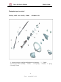
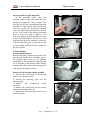
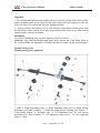
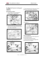
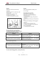
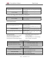
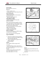
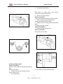
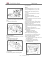
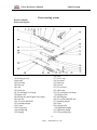
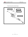
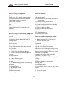
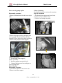
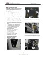
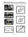
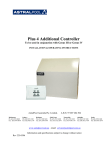
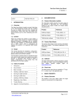
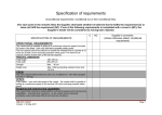
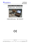
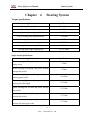
Chery QQ Service Manual
Chapter 4
Chassis System
Steering System
Torque specifications
Application
Specifications
Steering box installation nut
70-80Nm
Tie rod and rack fixture nut
63-77Nm
Tie rod end plane and steering knuckle fixture nut
32-38Nm
Power steering pump installation bolt
22-28Nm
Steering column and crosstree
13-17Nm
Steering knuckle and steering box
22.5-27.5Nm
Steering wheel and steering shaft nut
27-33Nm
Steering shaft flange clamping bolt
22.5-27.5Nm
Nipple torque specifications
Application
Specifications
Power steering oil hosepipe and power steering
pump socket
Power steering oil hosepipe and power steering
storage tank socket
Power steering high pressure hosepipe and power
steering pump socket
Power steering high pressure hosepipe and power
steering box inlet nipple
power steering box oil inlet and power steering
box socket
power steering box gusher pipe and power
steering box socket
power steering box gusher pipe and power
steering oil return pipe socket
88
Chery Automobile Co., Ltd
2-3Nm
2-3Nm
20-35Nm
27-33Nm
27-33Nm
27-33Nm
27-33Nm
Chery QQ Service Manual
Chassis System
Manipulate part overhaul
Steering wheel and steering column
decompose view
1. Steering universal coupling shaft and universal coupling; 2,3. Bolts;
4. Steering core shaft assembly; 5. Bolts; 6. Jump ring; 7. Washer; 8. Spring
9.Steering column
89
Chery Automobile Co., Ltd
Chery QQ Service Manual
Chassis System
Steering wheel free-play inspection
In the assembled mode, check the
free-play of the steering wheel while the car is
driving in straight line. The free play of the
steering wheel in the circumferential direction
should be no larger than 0~30mm. In the case
that the free play goes beyond the specified
value, the following items should be checked
to see: if the joint of the steering horizontal
lever is worn out (when a torque of over
0.2N.m is applied, the joint should be moved);
if the lower ball knuckle is worn out; if the
steering shaft universal coupling is worn out;
if the steering small gears or gear rack is worn
out or damaged and if the fixture or joining of
the parts is loose.
Control institute
Steering wheel Removal
Remove the battery jumper wires; remove the
steering wheel label cover assembly; remove
the steering shaft screw nut. To facilitate
positioning in the installation, matching signs
are to be made on the steering wheel and the
steering shaft, then remove the steering wheel
with the special purpose remover.
Removal of the steering column assembly
1) Remove the wire bundle of the steering
wheel cover and horn switch.
2) Remove the fastening screw nuts the
steering wheel.
3) Remove
the
combination
switch
assembly.
4) Remove the joining bolt for the steering
column and steering power tilt.
5) Remove the four fastening screws for the
steering column.
90
Chery Automobile Co., Ltd
Chery QQ Service Manual
Chassis System
Inspection
1、The steering shaft and universal coupling: check to see if the steering shaft is bent, or if the
spine is damaged; check to see if there are any cracks on the universal coupling, or if the free
play is too large. If so, replace the universal coupling assembly.
2、Steering column: check all the covers of the steering column stand, with the spaces from
the slot bottom within 1.00mm. If not, make proper replacements. Check to see if the steering
column is bent, cracked or deformed.
Installation
The order of installation steps is just the opposite to that for removal.
Attention: Apply alkali-based lubricating grease on the interior slot of the rubber sleeve of
the steering column, and tighten the associated bolts and screw nuts with the specified torque.
Manual Steering Gear
Manual steering gear components
1. Bolts; 2. Right supporting frame; 3. Right supporting frame sleeve;4. Right steering
horizontal lever joints assembly; 5. Right horizontal lever;6. Steering gear washer; 7.
Gear bearing stopper; 8. O-shaped ring; 9. Left horizontal lever; 10. Left steering
horizontal lever joints assembly; 11. Left supporting frame sleeve; 12. Left supporting
frame; 13. Bolt
91
Chery Automobile Co., Ltd
Chery QQ Service Manual
Chassis System
II、Removal of power steering gear
assembly
(I)Removal
Disassembly procedure
1. Put steering wheel forward and lock
steering, remove steering shaft.
4. Turn steering pivot left into gap of wheel,
pull the lever into engine compartment.
5. Push down and backwards to remove
steering pivot.
2. Loosen the nuts on two ends of steering
transverse lever and push out the ends of
lever from steering node.
Steps of installation
1. Turn steering pivot upwards and push the
pivot into gap of wheel
2. Insert pivot into front surround.
3. Screw the nuts between the support and
front surround ( not tighten).
3. Loosen the support and remove out.
92
Chery Automobile Co., Ltd
Chery QQ Service Manual
Chassis System
Fixture
Screw steering gimbal assembly with
22.5-27.5Nm.
Fixture
Install pivot on front surround with
70-80Nm.
Insert two ends of lever and screw with
steering node.
( Use new nuts) with 32-38Nm.
4.Put the pivot forwards.
5. Install steering gimbal assembly.
Description and operation
Instruction for steering system
The turning of steering will produce
following actions:
1. The motion of steering will transfer to
small gear
2. The motion of small gear will transfer to
gear.
3. The teeth of small gear will be joggled
with rack.
4. Rack will move under the force.
5. The force will transfer from transverse
lever to steering node.
6. Steering knuckle turn wheel
Steering wheel and steering column
Common problem and treatment measure
Lock system incapable open lock
Problem
Measure
Check this part
Lock core possible be damage
If need to replace part, refer “ The ignition
switch lock core replacing”
If need to replace part, refer “ The ignition
Ignition switch is wear out or damage
switch lock core replacing”
Lock system cannot lock u
Problem
Measure
Following parts possible be damage
Check unit
If need to replace part, refer “ The ignition
switch lock core replacing”
On close and locking position, cannot pull out key
93
Chery Automobile Co., Ltd
Chery QQ Service Manual
Problem
Ignition switch Lock core sets not correct
Lock core damage
Chassis System
Measure
Demand adjust Lock core
If need to replace part, refer “ The ignition switch lock
core replacing”
If need to replace part, refer “ The ignition switch lock
core replacing”
On Close and locking position, demand larger locking force
Problem
Measure
If need to replace part, refer “ The ignition switch
lock core replacing”
Lock core damage
Steering wheel looseness
Problem
Steering wheel installation nut is loose
Steering wheel damage
Steering intermediate shaft wear out or damage
Measure
1.Check steering wheel installation , refer “ The
steering wheel replace”
2. To fix steering wheel installation nuts, refer “ The
steering wheel replace”
1. Check steering wheel refer steering wheel replace
2. Steering wheel replace refer steering wheel replace
Check steering intermediate shaft, refer “ The power
steering box replace”
Replace steering intermediate shaft, refer “ The
power steering box replace”
chatter When turning steering wheel ,
can feel clearance
If steering shaft pin is no serious damage ,
advise to replace steering shaft
Steering shaft check
Check steering shaft plastics pin whether
sheering some symptom as follows
Steering shaft from flank slight dash have
Steering column looseness
Measure
Problem
Steering column installation bolt loose
Steering column stay unit loose or damage
Screw bolts to specified torque
1. Check steering column assembly
2. Repair or replace steering column assembly
Steering wheel looseness
Problem
Measure
Steering wheel installation nut looseness
Steering wheel damage
Steering intermediate shaft wear or damage
1. Check Steering wheel installation
2. Fix steering installation nut again
1. Check steering wheel
2. Replace steering wheel
Check steering intermediate shaft
Replace steering intermediate shaft r
94
Chery Automobile Co., Ltd
Chery QQ Service Manual
Chassis System
Service guide
Replace ignition switch core
Removal
1. Remove plastic cover
2. Insert needle into lock hole and pull out the
core from lock seat.
Steps of installation
1. Push the moving block to the direction
shown in the figure.
2. Insert the core into the seat.
Steering shaft replace
Disassembly procedure
1. Remove steering wheel from shaft.
Points of attention
Don’t knock steering when install or remove.
2. Loosen switch cover bolts. Remove signal
switch (left) and wiper switch (right). Loosen
the bolts between up/down shaft.
3.Loosen moving bolts on steering column
under instrument cluster.
4. Remove steering column.
5. Remove up steering shaft
Points of attention
The lower guide bearing is a rubber bearing.
Carefully remove the bearing.
Don’t put steering lock in lock position.
Steps of installation
1. Insert new up shaft into steering column.
Insert lower guide pipe into rubber bearing.
Push the bearing to the end.
2. Connect separate block, support, lower
support with bolts.
Use new locknuts.
Fixture
Screw support and lower support with
13-17Nm.
3. Insert shaft flange and fix. Insert harness
connector into signal switch and wiper switch.
Fix signal switch cover.
Fixture
4. Install steering wheel in steering shaft
Screw bolts with 22.5-27.5 Nm.
Screw bolts with 22.5-27.5 Nm.
Fixture
Screw steering nuts and shaft nuts with
27-33Nm.
5. Check forwards position of the steering
institution.
95
Chery Automobile Co., Ltd
Chery QQ Service Manual
Chassis System
3.
Loosen the safety bolts.
Drill holes on safety bolts with electric
screwdriver to pull out the bolts.
4. Remove steering column.
Points of attention
Don’t turn ignition switch in LOCK position.
5. Remove up steering shaft and lower
steering guide bearing from pillar.
6. Remove lower steering guide bearing from
pillar.
7. Replace steering column.
Steps of installation
1. Insert steering column screw.
Points of attention
Note guide ears on shell.
Steering column replace
Points of attention
Observe safety regulation during operating air
bag.
Remove procedure
1. Remove air bag unit and the steering
wheel with air bag.
2. Loosen the bolts.
2. Use 4 bolts to fix the shell and pillar.
96
Chery Automobile Co., Ltd
Chery QQ Service Manual
Chassis System
bag components.
Fixture
Screw shaft flange bolts to 22.5-27.5Nm.
Screw gear flange bolts to 22.5-27.5 Nm.
Screw steering wheel and shaft bolts to
27-33Nm.
10. Check forwards position for steering
mechanics.
Description and operation
Description Steering wheel and steering
column
Steering component can realize the functions
besides of steering.
1. Steering column
Steering can absorb energy. When crashing
happens, the pillar will shrink to reduce the
probability to hurt driver.
2. Ignition switch and steering lock Ignition
switch and steering lock can prevent stealing
vehicle.
3. Multi-purpose operation lever
Multi-purpose operation lever can control
following parts:
- High beam of head lamp
- Windshield wiper and cleaner
Remove and re-install steering pillar
Use specified bolts to fix the pillar to make
sure absorb engine action. Be careful to
remove or transport the pillar.
1. The drawer to remove steering wheel is not
recommended one.
2. The top of pillar is knock badly.
3. Something leans against the pillar.
4. The pillar falls off.
3. Use bolts to fix ignition lock shell and shaft
shell.
4. Insert new shaft into pillar.
Points of attention
Don’t turn steering and ignition lock in LOCK
position.
5. Push guide bearing into pillar.
6. Insert and fix steering shaft.
7. Screw bolts.
8. Install steering wheel with air bag and air
97
Chery Automobile Co., Ltd
Chery QQ Service Manual
Chassis System
Power steering system
Exterior identify
Power steering box
(16) Nut
(17) Cover cap
(18) Lock nut
(19) Dust cap
(20) Circlet
(21) Tie rod end
(22) Check nut
(23) Tie rod ripple cowl hoop
(24) Ripple cowl
(25) Steering box
(26) Tie rod in band ball unit
(27) Limiting stopper
(28) Tube
(29) Oil pipe clip
(30) Hydraulic piping
(31) Hydraulic piping
(32) Trust sealing ring
(1) Steering tie rod
socket unit
(2) Fixed ring
(3) Dust cap
(4) Lock
(5) Check nut
(6) Tie rod ripple cowl hoop
(7) Ripple cowl
(8) Steering box shell ripple cowl clamp
(9) Lock nut
(10) Tie rod in band ball
(11) Limiting stopper
(12) Circlet
(13) Facing ring
(14) Searing ring
(15) Bearing
98
Chery Automobile Co., Ltd
Chery QQ Service Manual
Chassis System
Power steering service schematic diagram
Steering oil
pump
Steering oil
tank
Steering oil
pipe
Power steering gear
99
Chery Automobile Co., Ltd
Chery QQ Service Manual
Chassis System
Steering system fizzy noise
Step
Measure
Yes
No
Identification: Fizzy noise is heard during Engine running or steering wheel turning
1
If the fizzy noise becomes loud When
TO step 2
System perfect
comparing with other normal vehicle?
2
3
4
5
6
7
8
If the fizzy noise becomes loud? If
steering fluid level is too low?
Fill fluid into the system.
Does customer still complain?
Is the noise from inside of vehicle?
The noise may enter passenger
compartment through outlet of front
instrument panel.
Repair or replace steering pillar seal.
Does customer still complain?
Make sure the lay for steering hose and
pipe is correct ( not touch with front
instrument panel).
Repair or replace hose and pipe if
necessary.
Does customer still complain?
Confirm The source of noise. Check
steering pump and steering institute.
Repair or replace parts if necessary.
Does customer still complain?
TO step3
TO step4
TO step1
System perfect
TO step5
TO step7
TO step6
TO step7
TO step1
System perfect
TO step8
System perfect
TO step1
System perfect
Steering system chatter noise
State
Measure
Ensure power steering wear refer hydraulic
Power steering system piping wear
piping replace
Fixture steering box nut torque refer
Steering box looseness
fastener specifications
Tie rod one end or both ends looseness
Steering universal joint looseness
Repair or replace tie rod end if necessary
Repair or replace the universal joint refer if
necessary
100
Chery Automobile Co., Ltd
Chery QQ Service Manual
Chassis System
Points of attention:
Don’t turn steering to the end and keep on. It
will damage pump.
5.5 Ask assistant to turn steering left/right for
several times.
5.6 Confirm leaking position and fix.
6. Go to following steps if repairing
6.1 Clean leaking position before removing
6.2 Replace the seal
6.3 Check if the seal is broken.
6.4 Screw bolts to specified torque.
6.5 Fill fluid to system.
Full filling/draining air
6.6 Draining air in system
Power steering box diagnosis
Fizzy noise
Some noise will be heard during steering in
fixed place under conventional condition.
Check if any leakage for system.
Check if air in system.
Turn sharply needs too much force in short
time.
Check if any leakage for inner pressure.
Check if the pressure in the pump is nor
enough.
Check if the fluid level is too low.
Power steering box and steering pump leak
Following symptoms show the leakage in
system.
Obvious fluid leak on steering pivot or pump.
Loud noise is heard during park brake or
cooling engine.
Lost power steering when park brake.
Heavy steering.
Check procedure
Go on following steps when check outside
leak in system:
1. Wipe doubt section.
2. Check if too much fluid in the tank.
3. Check if following situations appear in
system.
Air mixed in fluid.
Over flow.
4. Check following parts:
Hose connector.
O-ring
5. Confirm leaking position with following
methods:
5.1 Turn off engine.
5.2 Wipe whole system.
5.3 Check fluid level in tank.
Fill fluid if necessary.
5.4 Start engine.
Power steering box diagnosis procedure
1. Check if any leakage around connector.
2. Replace steering pivot if leak appears
between following parts
Wrest lever
Input shaft
3. Replace pivot if leak appears on driver’s
side and is not affected by steering.
4. Replace pivot if leak appears on top cover
and spray fluid when steering turn to left end.
Replace transmission shaft if there are serious
corrosion dots on the shaft.
Clear the shaft surface with cloth if the
corrosion on seal area is tiny.
Replace the shaft if there still is leakage after
clearing.
Suggestion to replace seal
Following parts needs special seal:
Steering pivot
Drive shaft of pump
Go to following steps if one of above leaks
appears:
1. Check seal section.
2. Clear seal section.
3. Replace seal.
101
Chery Automobile Co., Ltd
Chery QQ Service Manual
Chassis System
Points of attention
Residual fluid will flow out into the container.
Steps of installation
1. Put the tank into support and screw bolts.
Connect two hoses and fix clamp.
2. Check if any leakage in system.
Power steering pump replace
Disassembly procedure
1. Remove transmission belt and loosen adjust
bolts
Power
2. Remove high-pressure hose and pipe from
steering pump. The fluid will flow into the
container. Please observe the safety regulation.
3. Remove the pump from front support.
Steps of installation
1. Put the pump on the support]
Fixture: 22-28Nm.
2. Install strengthen transmission belt.
3. Connect high-pressure hose and pipe on
steering pump again.
Power steering
Disassembly procedure
1. Loosen two connectors and remove out.
2. Remove tank from support.
102
Chery Automobile Co., Ltd
steering
liquid
Chery QQ Service Manual
Chassis System
Rinse power steering system
Attention: Use suitable steering fluid when
filling or replacing fluid, otherwise it will
damage hose and seal.
1. Lift vehicle to run wheel freely.
2. Suck out fluid from tank.
3. Remove fluid hose from connector.
4. Insert outlet of hose into tank.
5. Put hose into container.
6. Run engine at idle. Ask assistant to fill
fluid into tank.
7. Turn steering wheel left and right.
Attention: Don’t turn to end for starring
wheel to keep on. Otherwise it will cause
over heat for system or damage pump and
pivot.
8. Continues to drain out all old fluid.
9. Resin system with 0.9L new fluid.
10. Check if all fluid is drained out.
11. Remove the cock of pump.
Points of attention:
Don’t use the fluid drained out.
12. Connect hose and tank.
13. Turn off engine.
14. Fill fluid into tank.
15. Check if any leak in tank.
16. Drain out air of system.
2. Loosen nuts on hose. Note to collect fluid.
3. Remove bolts on left/right transverse lever.
Power steering box replace
Disassembly procedure
1. Remove 3 bolts first.
103
Chery Automobile Co., Ltd
Chery QQ Service Manual
Chassis System
6. Push lower end of node to side of steering
pivot to disconnect up end with steering pillar.
4. Remove bolts on pivot.
7. Remove steering node assembly.
8. Remove steering assembly.
5. Loosen two bolts on steering node.
104
Chery Automobile Co., Ltd