1
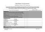
Specification of requirements
Unconditional requirements: Conditional (C) or Non Conditional (NC).
(For each point in the remarks field, the Supplier shall state whether he believes that he fulfils the requirement (C) or
does not fulfil the requirement (NC). If one of the following requirements is completed with a cross in (NC), the
Supplier’s tender will be considered as having been rejected.
C
SPECIFICATION OF REQUIREMENTS
NC
Supplier’s comments.
(Unless otherwise stated: conditional
requirement)
OPERATIONAL REQUIREMENTS
The vessel shall be capable of sailing at a continuous maximum speed of at least
23 knots in Sea State 1 with a full load and a propeller safety guard.
The fuel capacity should be sufficient to enable the inflatable boat to operate at 23
knots for at least 2 hours excluding propeller safety guard. The reserve fuel
capacity shall be at least 25% of the full fuel capacity.
PRINCIPAL DIMENSIONS
Total length
730–740 cm
Total width
295–305 cm
Draught
Max. 40 cm
Weight max.
Max. 1350 kg including outboard motor and
full tank
CREW
The crew onboard shall consist of a crew of 3, in addition to 7 men fully equipped
(10 men ≈ 1150 kg).
SPEED
Fully loaded – crew and total weight of the vessel – the vessel shall be capable of
sailing at a continuous speed of not less than 28 knots excluding propeller safety
guard.
Seagoing and manoeuvring capabilities
The vessel shall comprise a stabile platform with good seagoing and manoeuvring
capabilities – including when reversing – as the vessel may be operating
worldwide under particularly difficult wind and sea conditions
RIB-SVN 740/011
Version 1, 30 May 2011
Page 1
Materials
Materials shall be optimised with regard to strength and weight taking into account
the vessel’s operational use.
Approved modern materials and moulding techniques such as vacuum-moulding
or equivalent shall be used.
All metal components such as fittings, pipe constructions, bolts, nuts, etc., shall be
made from materials that are seawater-resistant, low in weight and sufficiently
strong with regard to the vessel’s operational use.
The hydraulic and fuel systems shall be designed in accordance with the
manufacturer’s instructions.
No clamp ring or die ring fittings or self-tapping screws shall be used in
connection with joints on the vessel or its systems.
There shall be no company logo or equivalent from the manufacturer on the
vessel.
Drawing – general layout and configuration – as well as material descriptions shall
be submitted to Danish Defence Acquisition and Logistics Organization (FMT),
enclosed with the tender as an appendix.
Regulatory basis:
The vessels shall fulfil the regulations in the SOLAS/LSA Code under the
designation “rescue boat”. In the version: “Semirigid Rigid inflatable”. The boat
and/or motors shall not fulfil the requirements for self-righting.
Deviations from the regulations shall be accepted in the following areas:
1. Fixed seats located within the buoyancy pontoons replaced by seats on
the pontoons with foot ropes in bottoms which people can use to provide
grip for their feet during sailing.
2. The human load shall be calculated using 100 kg per person for which the
boat is designed.
3. The name, home port designations and call sign identifications are
deleted and replaced by another FMT-determined identification system.
4. Handrails on the bottom are omitted. Insofar as is possible, a taut handline or similar is placed below the pontoon edge, which people in the
water can hold onto if the boat should capsize and float upside down.
5. Hoist hook of SVN standard type HENRIKSEN OFF-LOAD.
RIB-SVN 740/011
Version 1, 30 May 2011
Page 2
Certification:
Certification in accordance with the required regulatory basis with specified
deviations shall be carried out by one of the following independent competent
bodies:
1. A “Notified Body” authorised in accordance with the EU Directive on the
approval of marine equipment (MED).
2. A classification society authorised in accordance with the EU Directive
on the approval of classification societies (Recognised Organisations).
3. An EU maritime administration (EU National Maritime Administration).
4. Another equivalent body which on the basis of a specific assessment
can be accepted by the FMT authority section.
Each individual boat shall be supplied with a certificate that confirms that the boat
is of a type that fulfils the regulatory basis with the specified deviations. Using a
numbering system, it shall be possible to link the certificate to the individual boat
using a manufacturer’s plate with a corresponding number.
Hull design
The hull shall be optimised with regard to weight and strength – the cladding shall
be capable of withstanding slamming – taking into consideration the operational
use, at 20 knots in Sea State 4–5.
The hull shall be designed as a full V-hull, approx. 22º middle with spray edges
and approx. 18° - 20° at the transom.
Along the keel, the hull shall be reinforced internally such that damage caused by
external impacts/blows do not result in deep delamination.
The deck shall have an optimal area and be embedded in anti-slip coating.
Drainage screw(s) shall be fitted in the transom to drain the internal hull.
The vessel shall be designed with a closed transom of sufficient strength for fitting
two (2) F100 hp outboard motors.
The motor well shall be designed so that it takes up minimal space in the vessel
and has a size during sailing which means that the well self-bails before the water
reaches the deck, and so that outboard motors may be fully tilted upwards.
Bolt penetrations for the outboard motor shall be reinforced, with bushings where
appropriate.
The transom shall be fitted with two (2) bull-eyes so that a similar vessel can be
towed fully loaded at 15 knots via a crowfoot.
The transom shall be sufficiently strong to simultaneously support an outboard
motor F100 and permit towing on the crowfoot.
RIB-SVN 740/011
Version 1, 30 May 2011
Page 3
Watertight pipes for electrical and mechanical components shall be moulded into
the hull.
Self-bails from the cockpit shall be installed of sufficient capacity. Bilge pipes in
the inner hull shall be pressure-tested for impermeability. Bilge pipes shall be
terminated with a bailer or similar so that they are impermeable from the outside.
One (1) bull-eye with a tensile strength of 5000 kg.
Foremost in the vessel, 1 x clamp shall be installed for towing.
The clamp shall be dimensioned so that during rescue it can hold the vessel in an
aft trim half-filled with water and the vessel’s total weight, 2500 kg.
Reflectors shall be fitted to the hull and pontoon in accordance with the LSA
Code, Rescue Boat.
A type approval plate shall be fitted to the transom.
The transom shall be fitted with an identification plate with the following
description:
FARTØJET TILHØRER FORSVARET
Type:
RIGID INFLATABLE BOAT
Serial number:
RIB (length) – (serial number/year)
NSN:
194022xxxxxxx
VED FUND: KONTAKT SØVÆRNETS OPERATIVE KOMMANDO
PÅ TELEFON 00 45 89 43 30 99
Dimensions: W = 16.5 cm * H = 7.5 cm
Colour
The complete vessel, including pontoon, control panel, seat console, etc., shall be
finished in ORCA Orange Sylvano or equivalent (in the event of deviation, a
colour sample must be submitted with the tender).
Pontoon
The pontoon shall be designed with at least five separate compartments in
Hybalon, 1670 dtx 1500 gr/m2 or equivalent
The pontoon shall be designed with a flat nose, and aft shall be of a length which
means that the motor construction is cleared during turning.
Each compartment shall be equipped with an inflation and release valve of the
Leafield C7 and A6 type. The valves shall be sunk flush in the pontoon and easily
accessible for filling.
RIB-SVN 740/011
Version 1, 30 May 2011
Page 4
For the Jason’s Cradle rescue net – 4 cells wide – a black wearing piece and 2 x
D rings starboard and port shall be fitted to the pontoon adjacent to/in front of the
control console.
A strong fender strip in black shall be fitted from starboard aft to port aft.
Lifelines shall be fitted internally and externally starboard and port. These shall be
broken around the reinforcements for the Jason’s Cradle.
A swallow-tailed Danish flag shall be fitted aft externally starboard and port.
Dimensions: W = 34.5 cm x H = 7.5 cm.
A buoyant knife and rescue line with quoit and shall be fitted aft internally
starboard and port.
Internally, a sign clearly visible to the vessel driver shall be fitted internally stating
deadweight and total weight kg 2500.
Four holders for 1500mm wooden paddles shall be fitted starboard and port aft.
Holders shall be fitted such that they do not inconvenience the passengers.
6 x D-rings shall be fitted for lashing cargo in accordance with instructions.
CONSTRUCTION
The vessel shall have an optimal working/floor area in front of the control console
as a workspace for the storage of materials/equipment.
The entire deck shall be protected against blows and wear by impact-absorbing
loose rubber matting.
The vessel shall be equipped with a combined fixed control console, windscreen
in a tubular frame with grab-handle. The control console shall be as wide as
possible.
Aft of the control console, seating shall be fitted for two persons (2 x 1), with
adjustable back support and protected adjustable seat.
Fibreglass edges shall be protected against blows/impacts from heavy
materials/equipment – if appropriate by the fitting of rubber strips or similar.
A lifting tower with Henriksen 5-tonne releasing gear shall be fitted. The lifting
device shall be located 3250 mm in front of the aft edge of the pontoon. The
vessel shall be balanced such that the trim is horizontal or slightly aft trim max. 4°
(equipped and with a full tank). Two Neoprene-coated grab-handles shall be fitted
to the lifting tower.
The lifting device can be an integral component of the control console, but it shall
always have multiple legs for the sake of vessel stability. A multi-legged lifting
device that is not integrated into the console shall be capable of accommodating
equipment beneath of dimensions L=555 W=470 H=540. The tower shall be
designed such that neither it nor the Henriksen releasing gear obstructs the
outlook from the vessel.
RIB-SVN 740/011
Version 1, 30 May 2011
Page 5
The lifting device shall be load tested and approved to SWL 5tons
The control console shall contain/house the following:
xx-amp storage batteries for starting the outboard motor and supply. Steering
wheel, RPM counter, etc., gear/gas box, contacts for lanterns, lights, horn, chart
plotter and VHF radio, etc., on control console. On the side of the control column,
a socket for a 12V handheld searchlight, a socket for a charger and the main
switch for the storage batteries shall be mounted flush.
Storage batteries are to be installed in a fixed tray, secured to the hull/bottom by a
seawater-resistant bracket.
The front of the control console shall be fitted with a horn and handheld
searchlight with a range of at least 300 metres in clear daylight.
Hatches that are fitted in the control console or hull shall be watertight and impactresistant.
Foot ropes shall be installed starboard and port, both of which in front of the
control console. Foot ropes shall be of wire, with the facility to fit a cage-arresting
device. The device shall be designed so that 4 persons can be suspended freely
without compromising it. To be load tested.
The inner hull shall be capable of being emptied using a manual pump aft.
A Targa bracket shall be installed aft. The bracket shall be designed as a pipe
construction angled to not come in contact with another vessel/jetty if it rolls up to
45º.
The bracket shall be fitted with lanterns, 2 working lights, one with circuit breaker,
active radar reflector and various antennas. A Gusher 8 MK3 pump shall be
installed on the port side for bailing the inner hull.
MOTOR INSTALLATION
Two (2) 4-stroke outboard motors shall be fitted that fulfil the regulatory basis as
well as operational requirements for seagoing properties, including all the
necessary components.
Gear/gas box with powertrim and key switch shall be placed on the starboard side
of the console.
It shall be possible to read at least the following on an instrument panel: trim,
RPM, tank level, oil alarm, coolant alarm and charger amps.
Wires and cables from the gear/gas box shall be ducted in maintenance-friendly
cable duct(s) from the motor/Targa bracket to the console.
The installation shall be designed such that maintenance, trouble-shooting and
necessary replacement of components is feasible at user level.
RIB-SVN 740/011
Version 1, 30 May 2011
Page 6
TANK INSTALLATION
1 x CE-approved petrol tank which fulfils previously established requirements
shall be installed. The tank and associated system shall be approved in
accordance with the applicable rules.
The tank shall be equipped with venting, refuelling and cleaning covers.
Two (2) water separation filters shall be fitted to the fuel system.
The tanks shall be secured and supported so that these do not rupture.
The fuel system shall comply with the outboard motor manufacturer’s instructions.
ELECTRICAL INSTALLATIONS
Storage batteries shall have sufficient output to enable a cold outboard motor to
be started 6 times in succession and to support electrical components for 4 hours.
Via the main switches, it shall be possible to start the outboard motors on battery
1, battery 2 or both batteries simultaneously.
It shall be possible to isolate batteries via a key main switch.
A watertight contact panel for miscellaneous installations shall be placed
appropriately on the control console. The contact panel shall be complete with
circuit breakers and terminal blocks.
• Chart plotter
• VHF Sailor radio
• Navigation lights
• Active radar reflector
• Working lights
• Search light
• Instrument lighting and compass
• 4 additional sockets.
The contacts must be adapted to the individual functions and clearly labelled.
Terminal blocks shall be labelled in accordance with the circuit diagram.
The charger configuration is to be designed in accordance with the LSA Code.
The following equipment shall be used in connection with the installation:
Ladac Life Boat Charger
Plug
216BAU1W
Casing
GP216
700110
ABB no. 2CMA166684R1000
ABB no. 2CMA164993R1000
10 amp fuses shall be used between storage batteries and the charger.
Outside the console, cables and wires shall be ducted in maintenance-friendly
cable ducts, and on towers, they shall be screened/protected from overload.
RIB-SVN 740/011
Version 1, 30 May 2011
Page 7
A red LED light that flashes when the radar reflector is switched on shall be
located on the console.
Cables and wires on the tower shall be connected together using waterproof plugs
so that the tower can be removed.
LOOSE EQUIPMENT
Unless stated otherwise in this specification, a delivery shall be deemed as being
a shipyard delivery (delivery, assembly and testing).
1 x tarpaulin PVC fabric 600 gr/m² covering the entire vessel including outboard
motors in a pale grey colour.
1 x tarpaulin PVC fabric 600 gr/m2 covering control console.
Tank gauge of the Wema sensor type for integration in the instrument for the
outboard motor.
Danish Standards-approved 2 kg powder fire-extinguishers including brackets
intended for maritime use.
Water separation filter of the Quicksilver 802893Q01 type.
Guy suitable for the Henriksen releasing gear, max. length 400 mm with painter,
500 mm, in fluorescent colour, fitted in the rigging ring.
LED assembled starboard/port and masthead light.
Thrane & Thrane VHF Sailor radio 6210.
RayMarine marine chart plotter A70 – 6.5”.
Active radar reflector
Two (2) 4-stroke outboard motors complete with instrument fitted with propeller
protector.
SeaStar hydraulic steering complete with wheel.
Wheel with metal spokes, Ø 35 cm.
Compass, black, inbuilt with light.
Performance of the work
All electrical installations shall be carried out using standard – manufacturersupplied – cables with moulded plugs and/or marine-approved cables.
Installations/components shall be installed on a suitable watertight wooden sheet,
bracket, etc., in order to ensure adequate mounting and to provide strain relief for
cables.
All wires that are installed using spade terminals shall be of the “closed type” and
protected using heat-shrink with adhesive. All + cables shall be indicated by red
heat-shrink. Other cables shall be indicated by black.
All cable and wire dimensions shall be appropriate for their use and documented.
Connections that are deemed to be non-standard shall be made using closed
connectors. All connectors and open connection points shall be sealed.
RIB-SVN 740/011
Version 1, 30 May 2011
Page 8
All penetrations of the hull and into closed spaces in the control console shall be
watertight, minimum IP X7.
All cables/wires shall be laid in cable trays – logically distributed – where they are
secured/stripped carefully and appropriately.
Electrical installations shall be located so as to be maintenance-friendly (it MUST
be possible for the user to service/replace such installations), clearly marked at
both ends and without any form of separation of the control console.
Documentation
Drawings shall be supplied on an electronic medium in AutoCad version 2006.
The following shall be included in the delivery in one example per unit and FMT
(13 sets), and on an electronic medium – DWG, Word, PDF –, with one example
to contain original documentation, to be supplied to FMT.
All documentation that is supplied under this point and in connection with this
specification shall upon handover be deemed to be the property of FMT and may
in future be used in connection with invitations to tender.
At least the following drawings shall be supplied:
¾ General layout and configuration.
¾ Specification of materials.
¾ Embedded fittings, etc.
¾ Body plan.
¾ Line drawing.
¾ Control console.
¾ Tower and aft bracket.
¾ Detail drawing of misc. fittings, etc.
¾ Petrol tanks.
¾ Pipe/installation diagrams of the petrol system.
¾ Pipe/installation diagrams of the hydraulic system.
¾ Electrical diagrams (single-line and connection
diagrams).
At least the following certificates shall be supplied:
¾ The vessel.
¾ Henriksen releasing gear
¾ Outboard motors
¾ Weight complete excluding fuel and equipment.
¾ Materials and equipment used.
¾ Lanterns.
¾ Petrol tanks and installation.
¾ Lifting point and test loading.
¾ Hoses and pipes for petrol/hydraulic systems.
RIB-SVN 740/011
Version 1, 30 May 2011
Page 9
At least the following information material shall be supplied:
The following information manual(s) shall be prepared by the Supplier,
irrespective of whether the equipment is supplied by FMT or the manufacturer.
Information manual(s) shall cover all installed equipment.
¾ Drawings and bill of materials. The bill of materials
shall state the manufacturer’s article number and
include a field for NSN.
Technical equipment that is supplied with the
components.
¾ User manual with pictures and descriptions of
the functions.
User maintenance – daily, weekly, monthly and before and after sailing – of all
installed equipment for which there are maintenance requirements, in Danish.
Current spare parts
The Supplier shall supply a list with a recommendation of current spare parts for
the installed equipment.
The list shall contain the original manufacturer – name, address, etc. – the
manufacturer’s product designation and article number, and Danish importer with
article number.
Makes/manufacturers
All equipment that is to be supplied in connection with or for the vessel shall be
documented with the original manufacturer – name, address, etc. – the
manufacturer’s product designation and article number, and Danish importer with
article number.
Test:
FMT to be called in in connection with type approval test and load tests.
Production plan to be forwarded, stating test procedure.
Handover
The vessel shall be supplied approved, assembled, equipped and in operational
condition.
All materials, components and systems shall be tested in the presence of FMT
and to FMT’s complete satisfaction.
The Supplier shall prepare a technical control booklet in collaboration with FMT.
The shipyard shall carry out a technical test voyage prior to delivery.
RIB-SVN 740/011
Version 1, 30 May 2011
Page 10