1
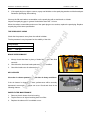
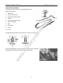
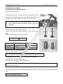
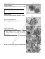
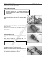
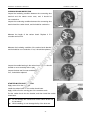
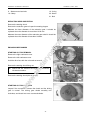
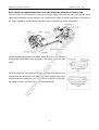
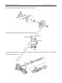
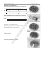
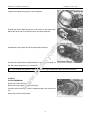
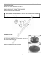
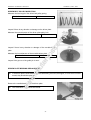
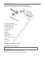
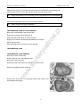
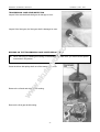
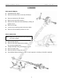
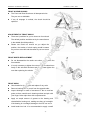
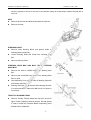
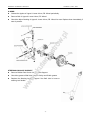
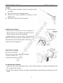
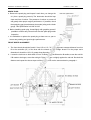
KINROAD 150 SERVICE MANUAL
VERSION 1, DEC., 2005
KINROAD
1
KINROAD 150 SERVICE MANUAL
VERSION 1, DEC., 2005
FOREWORD
This service manual has been specially prepared to provide all the necessary information for the proper
maintenance and repair of the KINROAD 150.
The KINROAD 150 fits the needs of a wide variety of KINROAD users above 16 years old. Those
who will be servicing this KINROAD should carefully review this manual before performing any repair or
service.
All information, illustrations, photographs and specifications contained in the manual are based on the
latest product information available at the time of publication. Due to improvement or other changes, there
may be some discrepancies in this manual. Therefore, if newest information is requested in the future,
please contact the local distributor.
Distributor reverse the right to make production changes at any time, without notice and without incurring
any obligation to make same or similar changes to vehicles previously built or sold.
2
KINROAD 150 SERVICE MANUAL
VERSION 1, DEC., 2005
CONTENTS
1. GENERAL INFORMATION -------------------------------------------------------------------------------------------------4
2. PERIODIC MAINTENANCE AND TUNE-UP PROCEDURES -----------------------------------------------------7
3. ENGINE --------------------------------------------------------------------------------------------------------------------------13
4. ELECTRIC SYSTEM ---------------------------------------------------------------------------------------------------------64
5. CHASIS --------------------------------------------------------------------------------------------------------------------------74
6. WIRING DIAGRAM -----------------------------------------------------------------------------------------------------------81
3
KINROAD 150 SERVICE MANUAL
VERSION 1, DEC., 2005
1. GENERAL INFORMATION
MODEL IDENTIFICATION
FRAME NUMBER
The frame number or VIN is stamped under the seat on the frame cross member and stuck behind the seat.
ENGINE NUMBER
The engine number is located on the lower front left side of the engine cases.
4
KINROAD 150 SERVICE MANUAL
VERSION 1, DEC., 2005
FUEL AND OIL RECOMMENDATIONS
Be sure to use the specified fuel and oil.
FUEL
Gasoline should SAE 90# or higher.
Unleaded gasoline is recommended.
ENGINE OIL
SAE10W-30 engine oil of high quality should be used.
BREAK-IN PROCEDURE
For the first 2 hours of riding, do not exceed 2/3 throttle.
Vary engine speed for the first 5 hours.
Never hold engine at full throttle for long periods of time.
SPECIFICATIONS
DIMENSIONS
DOUBLE SEAT/SINGLE SEAT
Overall Length
2159mm/2075mm
Overall Width
1400mm/1235mm
Overall Height
1470mm/1400mm
Wheelbase
1499mm/1450mm
Ground Clearance
170mm/130mm
ENGINE
Type
Forced air-cooled, single cylinder, 4-Stroke
Engine Capacity
150cc
Displacement
149.5cc
Bore x Stroke
57.4mm x 57.8mm
Compression Ratio
9.2:1
Max Power
7.4kw/7500rpm
Max Torque
9.5N.m/5500rpm
Fuel Type
SAE 90# or above (unleaded)
Lubricate Oil
SAE 10W/30
Ignition
C.D.I.
Starting
Electric
Spark Plug
C7HSA (NGK)
Transmission
Automatic C.V.T.
Carburetor
MIKUNI, BS24J
Lubrication
Force & Splash
5
KINROAD 150 SERVICE MANUAL
VERSION 1, DEC., 2005
CAPACITIES
Maximum Load
400lbs
Fuel Tank
7.0L
Engine Oil
850ml
Starting
<5s
6
KINROAD 150 SERVICE MANUAL
VERSION 1, DEC., 2005
Tire pressure/wear
I
I
Brake performance
I
I
Tightness of screws
I
I
Air cleaner
Carburetor
C
I
A
Spark plug
Drive chain
C
C
C, A
I
I
Brake fluid
C, A, L
I
Replacement of gearbox oil
Chassis
I
R
C, I
L
Fuel switch/fuel tank
Battery
C
I
Engine oil
I
R
Valve clearance of engine
A
A: adjust
C: clean
I: inspect, clean or replace if necessary.
L: lubricate
R: replace
MAINTENANCE AND TUNE-UP PROCEDURE
This section describes the servicing procedures for each item in the
Periodic Maintenance Intervals.
SPARK PLUG
Clear up the carbon around the spark plug to prevent it from dripping into
the cylinder when removing the spark plug.
Remove the spark plug
1.
I
In general, it should be carried on after the engine is cold.
KINROAD 150 SERVICE MANUAL
2.
VERSION 1, DEC., 2005
If the spark plug is too tight to remove, spray rust inhibiter on the spark plug washer and the thread part.
Rotate the spark plug after soaking.
Clear up the filth and carbon accumulation on the spark plug with a steel brush or a blade.
Inspect the spark plug gap; in general it should be about 0.6 - 0.8 mm.
When the carbon accumulation and wear of the spark plug are too serious, replace the spark plug. Replace
a spark plug of the same specification.
TIRE PRESSURE / WEAR
Check the tire pressure every time the vehicle is ridden.
The tire pressure is very important for the stability of the ride.
Tire pressure
Front
175 kpa
Rear
200 kpa
BRAKE PERFORMANCE
1.
Always check that there is plenty of brake fluid in the brake fluid
reservoir.
2.
Check that the front/rear brake pads are in good condition
3.
Check the brake rotor for abnormal wear.
AIR CLEANER
Clean the air cleaner quarterly or more often in dusty conditions.
If the air cleaner is clogged with dust, performance will be severely
decreased; even engine damages can occur. Check and clean in the
following manner.
PAPER FILTER MAINTENANCE
1.
Remove the air cleaner from its housing.
2.
Tap the filter on an object knocking dust from filter.
3.
Replace the element if it is wrinkled or torn.
9
KINROAD 150 SERVICE MANUAL
VERSION 1, DEC., 2005
FOAM FILTER MAINTENANCE
1. Remove the foam filter from steel cage
2. Wash in non-flammable cleaning solvent
3. Submerge in oil and squeeze to remove excess oil
4. Install the element back into the air box.
NUTS AND BOLTS IN THE CHASIS
Inspect first week and every month thereafter.
Always pay attention to the nuts and bolts. Some loosening after use is a normal situation and should be
checked regularly.
TIGHTENING TORQUE TABLE
Conventional marked bolt
8.8 marked bolt
10
KINROAD 150 SERVICE MANUAL
VERSION 1, DEC., 2005
“ON” position
The normal operating position for the fuel valve lever is the “ON” position.
In this position, fuel will flow to the carburetor.
“RES” position
If the fuel lever in the fuel tank becomes too low for the engine to operate
with the fuel valve lever in the “ON” position, turn the lever to the “RES”
position to use the reserve fuel supply, and refuel as soon as possible.
"OFF" position
The closing position for the fuel valve lever is the "OFF" position.
When the vehicle is not in use, always make sure the petcock is in the "OFF" position
FINAL GEAR OIL
Inspect monthly and change quarterly.
1.
To check the oil level, remove the level screw on the left rear engine
case.
2.
To drain oil, remove the drain plug at the rear bottom of the engine
case. It is recommended to warm the engine for 10 minutes or more
before draining final gear oil.
NOTE:
Mobil 85w/90 gear oil is recommended in the final drive case. However, in extreme cold weather conditions,
you may experience the vehicle to be hard to start. It is then advised to use lighter viscosity oil, such as 75
wt, or equivalent motorcycle transmission fluid.
Gear Oil Capacity
0.2L
85w/90
11
KINROAD 150 SERVICE MANUAL
VERSION 1, DEC., 2005
ENGINE OIL
Inspect every time before riding. Replace monthly.
1.
Remove the drain plug from the left side bottom of the engine. Drain
into oil pan for disposal.
2.
Remove the large cap on the left bottom of the engine and remove
the screen.
3.
Wash the screen with cleaning solvent and refit, making sure the
O-ring is still in good conditions.
4.
Refill the engine with SAE10W/30SF engine oil and run for 5 minutes.
5.
Check oil level on the filler cap stick to assure proper level.
6.
The cap needs to be screwed in to check.
CHASSIS
1.
Grease chassis bushings and bearings with grease quarterly to assure smooth operation and extended
life of the bushings and the components.
2.
If used in extreme wet and muddy conditions or dusty conditions, it is recommended to service more
often.
12
KINROAD 150 SERVICE MANUAL
VERSION 1, DEC., 2005
3. ENIGNE
CYLINDER
CYLINDER REMOVAL
The removal can be done on the vehicle body.
Remove cylinder head.
Remove cylinder.
Remove cylinder gasket, bolts.
Erase cylinder gasket.
1. Do not damage the bond area of the cylinder.
2. Do not drop sundries, such as cylinder gasket material into the crankcase.
CYLINDER INNER WALL WEAR INSPECTION
Use a bore diameter dial gauge to measure the degree of wear.
The measuring point is divided into three
sectional planes in the axial direction: upper,
middle, lower; measure every plane each
time on the mutually perpendicular directions
(X, Y). The least measured dimension is the
cylinder bore; the data measured at the most
upper position is the largest diameter, and
the lower position is the smallest diameter. At the same cross section, measure the difference of diameter
between two points mutually perpendicular, which is the circularity of the cylinder.
In order to make the measuring point perpendicular with the bore axis of the cylinder,
and to ensure the precision of the measurement, the bar of the gauge can be slightly
swung in the direction of the gauge bar, and take the smallest reading number as the
result.
In the situation without a dial gauge, a feeler gauge can be used to make relativity measurement. Put a new
piston into the cylinder, and use the feeler gauge to measure the gap between the piston skirt and the
cylinder wall, and then figure out the abrasion loss of the cylinder.
If the circularity of the cylinder exceeds the limit, a cylinder-reboring machine should be used to re-bore the
13
KINROAD 150 SERVICE MANUAL
VERSION 1, DEC., 2005
cylinder, and to enlarge its diameter by 0.50mm or 1.00mm, then fit the piston and piston ring whose sizes
are also enlarged. If the wear is too severe and cannot be reworked, a new cylinder should be installed.
Cylinder bore
57.4mm
Cylindricity
0.05mm
Circularity
0.05mm
CRANK CONNECTING ROD MECHANISM
PISTON SET
PISTON PIN INSPECTION AND SERVICING
Insert the piston pin horizontally into the pinhole of piston, and inspect the clearance between piston and
piston pin.
Service limit
0.02 mm
If the free play is too much, the worn condition of piston pin and the pinhole of piston must be inspected
respectively.
Measuring the external diameter of piston pin.
Service limit
14.96 mm
If the result is less than service limit, it should be replaced.
After replacement, the clearance between piston pin and the pinhole of piston must comply with the
requirement.
Measure the inner diameter of piston pin.
Service limit
15.04 mm
If the result is more than service limit, it should be replaced.
After replacement, the clearance between the pinhole of piston and piston pin must be sure to comply with
the requirement.
PISTON RINGS INSPECTION AND SERVICING
Inspect if there is a flaw, serious wear, or serious conglutination on the piston ring. If there is, it should be
replace.
If the piston ring’s lateral clearance and notch clearance are too large or too small, malfunction may be
caused. So it must be measured.
Measure the clearance of piston ring in the piston ring groove. This clearance is the piston ring’s lateral
14
KINROAD 150 SERVICE MANUAL
VERSION 1, DEC., 2005
clearance.
First ring
0.09 mm
Second ring
0.09 mm
CONNECTING ROD END INSPECTION
Put the piston ring and bearing into the connecting rod end; inspect the degree of tightness of the piston pin
in connecting rod end.
Measure the inner diameter of the connecting rod end.
Service limit
15.06 mm
When the abrasion of the bore exceeds the limitation, it should be replaced.
PISTON RING SET
Before setting up, apply oil on every piston ring, and then enlarge piston rings. AT the same time cover
them on the piston and move forwards gradually until piston rings fall into the ring groove.
PISTON RING INSTALLATION
Remove the gasket attached to the crankcase.
Mount piston onto the small end of the connecting rod.
The top of the piston with “IN” mark should be mounted towards the direction of the inlet port
(If the mark is “EX”, it should be mounted towards the direction of the exhaust port.)
Mounting piston pin and piston pin clip.
Apply oil on the piston pin to lubricate it.
Cover a piece of cloth on the crankcase port to avoid the piston pin clip from dropping into the
crankcase.
15
KINROAD 150 SERVICE MANUAL
VERSION 1, DEC., 2005
CRANK CONNECTING ROD SET
The connecting rod is the component that link piston and crank.
The picture shows the structure and assembly relations of the crank connecting rod component.
CRANKCASE AND CRANKSHAFT REMOVAL
Take the following procedures when removing the crankcase and
crankshaft.
Remove the engine.
Remove the cylinder cover
Remove the cylinder
Remove the piston
Remove the drive plate and the driven plate.
Remove the AC generator.
Remove the starting motor.
Remove the oil pump.
Then remove the cam chain tensioner bolt. Remove the cam chain
tensioner.
16
KINROAD 150 SERVICE MANUAL
VERSION 1, DEC., 2005
Use special tools to remove the starting driven gear.
Remove the crankcase positioning bolts.
Separate the right crankcase and the left crankcase.
The joint face cannot be damaged.
Remove the gasket and the dowel pins.
Remove the crankshaft from the crankcase.
Take out the cam chain.
Clean up the gasket on the crankcase joint face. Pay attention not to
damage the joint face.
Remove the oil seal from the left crankcase.
17
KINROAD 150 SERVICE MANUAL
VERSION 1, DEC., 2005
Remove the oil seal from the right crankcase.
CRANKSHAFT AND CRANKCASE INSPECTION
Replace the whole set of the crankshaft if serious wear is found while inspecting.
Measure the axial clearance of the big end of the connecting rod.
When measuring, make one side of the connecting rod big end close to the crank, and insert the feeler
gauge between the other side and the crank and get the correct end play.
Service limit
0.55 mm
Measure the radial (X, Y) clearance of the big end of the con’rod.
Service limit
0.05 mm
Measure the main shaft jump of the crankshaft.
If the crank jump is too much, it will cause the engine to shake abnormally, and shorten the life of the engine.
So it must be examined carefully when inspecting.
Service limit
0.10mm (A = 90)
0.10mm (B = 105)
Examine if there is any looseness, or unusual sound when the crank journal bearing turns. If there is, the
whole set should be replaced.
Inspect if the joint face of the crankcase is smooth and clean, and notice if it will affect the sealing
performance between the left and right crankcase while reassembling.
After the above inspection, use oilstone to furnish the crankcase if it has some surface damage. Replace
cover if damage is too severe.
The right and left crankcase axle hole must be concentric, so generally they must be replaced at
the same time.
18
KINROAD 150 SERVICE MANUAL
VERSION 1, DEC., 2005
KINROAD 150 SERVICE MANUAL
VERSION 1, DEC., 2005
VALVE MECHANISM INSPECTION AND SERVICING
The picture shows the common valve train of a four-stroke engine. This is a kind of overhead valve; its
intake port, exhaust port, camshaft are all located in the cylinder head; the valve bottoms up over the
combustion chamber.
GENERAL INTRODUCTION
The four-stroke engine completes its four stroke with one piston stroke.
Intake stroke
Compression stroke
Expansion stroke
Exhaust stroke
VALVE CLEARANCE ADJUSTMENT
Valve clearance is an important technical parameter.
Make sure that the valve can close tightly under any conditions, especially when the engine is overheated;
there must be certain clearance kept when the valve is in the cold condition. This clearance is called valve
clearance. When the engine is running, the valve clearance should be neither too big, nor too small. So the
valve clearance adjustment is an important procedure in the valve maintenance.
Remove the cylinder head cover.
20
KINROAD 150 SERVICE MANUAL
VERSION 1, DEC., 2005
Turn the cooling fan clockwise until the mark of the timing drive
sprocket on the camshaft is at top dead center, and the "T" symbol
(or other mark) of the magneto flywheel aligns with the crankcase
mark.
The crankshaft should co-rotate; otherwise the
exhaust port may not be adjusted.
When adjusting, loosen the lock nuts; adjust the bolts with a
valve-adjusting wrench; if turning clockwise, the valve clearance
decreases, and if turning counterclockwise, the valve clearance
increases. Then, put a feeler gauge with specific size between valve
and rocker to check for correct clearance.
Take out the feeler gauge; tighten the lock nuts, and then inspect the
valve clearance again.
Sometimes when tightening the lock nuts,
it will change the clearance. So it must be
rechecked for the proper clearance.
Valve clearance
0.06~0.07 mm
CAMSHAFT
The camshaft is a main driving unit of the valve train. There are the air inlet cam, the exhaust cam, and the
cam journal on the shaft. It controls the intake and exhaust valve to open and close at the correct time. The
camshaft wear will affect engine performance and cause excessive noise
CAMSHAFT REMOVAL
Loosen valve cover bolts and remove cover.
Remove the cam chain tensioner screw, and remove the O-ring.
Tighten the cam chain tensioner-adjusting bolt clockwise.
21
KINROAD 150 SERVICE MANUAL
VERSION 1, DEC., 2005
Turn the flywheel counterclockwise to make the "T" mark on the flywheel align with the mark on the
crankcase. When the hole on the cam chain (timing drive chain wheel) is up, it is the top dead center
position.
Remove the cylinder head positioning bolt.
Remove the camshaft holder bolt cap, washer.
Remove the camshaft holder and dowel pin.
Remove the cam chain wheel from the cam chain, and remove the
camshaft.
CAMSHAFT INSPECTION
Inspect if the camshaft bearings for play. If they are, then replace the whole set.
Inspect cam surface for damage
Measure the height of the cam.
Inlet cam
25.96 mm
Exhaust cam
25.815 mm
CAMSHAFT INSTALLATION
Rotate the flywheel to align the "T" mark on the flywheel with the camshaft mark. The round hole on the
cam chain wheel should be up. The left and right sit parallel with the cylinder head (the lobes of the
camshaft are down). Install the camshaft on the cylinder head.
Mount the cam chain on the cam chain wheel.
Install the dowel pins.
Mount the camshaft holder, washer, and nut on the cylinder head
Tighten the cylinder head bolt and nut.
1.
While installing, first apply some oil on the thread part of the camshaft holder bolt.
2.
The camshaft nuts should be tightened diagonally in a 3-step process.
3.
After installing, adjust the valve clearance.
22
KINROAD 150 SERVICE MANUAL
VERSION 1, DEC., 2005
Turn the cam chain tensioner adjusting bolt counter-clockwise and
release the lock.
Apply oil on the new O-ring.
Mount and tighten the cam chain tensioner cover bolt.
The o-ring must be mounted properly in the groove.
Replace the valve cover gasket, and mount the cover
The valve cover gasket must be mounted properly in
the groove.
Tighten the valve cover-positioning bolt.
ROCKER ARM AND ROCKSHAFT
ROCKER ARM AND ROCKSHAFT REMOVAL
Remove the camshaft holder.
Take out the rockshaft by removing the bolt.
Remove the rocker arm.
ROCKER ARM AND ROCKSHAFT INSPECTION
Inspect if there is any abrasion or damage on the rocker arm and rockshaft or if the oil hole clogged.
If there is abrasion on the surface of the rocker arm, the camshaft should also be
inspected.
Measure the inner diameter of the rocker arm.
Service limit
10.10 mm
Measure the outer diameter of the rockshaft.
Service limit
9.91 mm
ROCKER ARM AND ROCKSHAFT INSTALLATION
Read the "EX" mark on the camshaft holder, then mount the exhaust port rocker arm and the rockshaft.
After that, mount the inlet port rocker arm and rockshaft.
Apply some oil on the rockshaft before mounting it on.
23
KINROAD 150 SERVICE MANUAL
VERSION 1, DEC., 2005
CAM CHAIN TENSIONER
The chain tensioner must be in good working order for
proper chain tension.
1.
Cam chain
2.
Cam chain tensioner
3.
Cam chain tensioner lifter
4.
Gasket
5.
Cam chain tensioner pivot
6.
Cam chain guide
7.
Bolt
8.
Screw pan
9.
O-ring
10. O-ring
The operational principle of the tensioner is as shown in the picture.
As for the adjustment of the cam chain tensioner, turning clockwise
is tightening, and turning counterclockwise is loosening.
24
KINROAD 150 SERVICE MANUAL
VERSION 1, DEC., 2005
VALVE AND VALVE SPRING
VALVE AND VALVE SPRING REMOVAL
Remove the cylinder head.
First remove the valve cotter with the valve compressor, and then
remove in turn the upper spring race, valve spring, lower spring race,
and valve stem oil seal. Remove the valve from the other side.
The removed parts should be placed properly in order. It's
better to place the intake valve parts and exhaust valve parts
separately.
VALVE AND VALVE SPRING INSPECTION
Inspect to see if the valve is bent or burned.
Inspect if the action is smooth between the valve and the valve
guide.
Measure the outer diameter of the valve stem.
Service limit
4.9 mm
Measure the free length of the inner and outer valve spring.
Valve
Inlet valve
Exhaust valve
Inner spring
31.2mm
31.2mm
Outer spring
34.1 mm
34.1 mm
VALVE AND VALVE SPRING INSPECTION
Mount the spring retainer, valve guide oil seal
It is recommended to replace the valve guide oil seal with a new one.
After applying oil on the valve stem mount it into the valve guide
Mount the inner and outer valve springs,
Mount the valve locker with a spring compressor.
When mounting, the twisting direction of the inner and outer springs must be opposite, and
cannot be the same.
Tap at the valve gently two or three times with a rubber hammer to make the valve and the valve lock match
well.
Do not damage the valve.
25
KINROAD 150 SERVICE MANUAL
VERSION 1, DEC., 2005
VALVE GUIDE
Carbon accumulation of the valve guide will make the valve move rough, causing the valve not to open or
close properly.
Valve guide abrasion is one of the reasons that cause the exhaust pipe fuming white smoke.
CLEAN CARBON ACCUMULATION OF THE VALVE GUIDE
Remove the valve and valve springs.
Clean the carbon accumulation with a valve guide reamer.
VALVE GUIDE INNER DIAMETER MEASUREMENT
Service limit
5.03 mm
Calculate the clearance between the valve stem and the valve
guide.
(The inner diameter of the guide subtracts the outer diameter of the
valve stem).
Valve
Inlet valve
Exhaust valve
Service limit
0.08mm
0.10mm
26
KINROAD 150 SERVICE MANUAL
VERSION 1, DEC., 2005
After tapping the valve guide, you need to trim it with a reamer.
Clean the cylinder head and eliminate the scraps generated while
reaming.
VALVE SEAT
The relative position between the valve seat and the working surface of the valve is very important for the
valve to seal properly.
VALVE SEAT WIDTH MEASUREMENT
Clean the carbon accumulation in the combustion chamber.
Measure the width of the valve seat with a vernier caliper.
Standard
1.0mm
Service limit
1.8mm
27
KINROAD 150 SERVICE MANUAL
VERSION 1, DEC., 2005
KINROAD 150 SERVICE MANUAL
VERSION 1, DEC., 2005
If the valve seat still cannot contact evenly with the valve after trimming, the valve should be revised or
replaced.
VALVE AND VALVE SEAT LAPPING
After finishing, the valve and valve seat should be lapped in order
to make them seal properly
Spread a thin layer of silicon carbide on the working bevel of the
valve, and use a valve suction cup tool. Then repeatedly rotate the
valve suction cup to lap the valve and valve seat evenly until they
match tightly.
Before lapping, clean the valve, valve seat and valve guide.
When lapping, do not use too much force.
During lapping, do not drop any silicon carbide into the place between the valve lever and the
valve guide.
VALVE AND VALVE SEAT AIR IMPERMEABILITY INSPECTION
After lapping the valve and valve seat, the air impermeability of their joint surface should be inspected.
Method one: same as the method of "valve seat contact position inspection”.
Method two: evenly draw several lines on the working surface of the
valve with a pencil. Put the valve into the valve seat, if the lines are all
broken after turning 1/8 - 1/4 ring, then it shows the air impermeability is
good.
Method three: mount the valve on the cylinder head, and fill the inlet and
exhaust vent with non-flammable solvent, and preserve for 5 minutes. If there is no leaking, the valve is
seated correctly.
29
KINROAD 150 SERVICE MANUAL
VERSION 1, DEC., 2005
LUBRICATION SYSTEM INSPECTION AND SERVICING
GENERAL INTRODUCTION
The picture shows the functional diagram of the lubrication system. After the lubrication oil crosses the filter
screen, it is pumped by the rotator oil pump; some of it goes into the big end of the connecting rod, and
splashes on the cylinder wall and the small end of the connecting rod; the other goes through some oil
passages, such as the shaft neck of the camshaft, and splashes on the cam rockshaft and cam chain. The
lubrication oil that falls back into the oil groove can be re-circulated.
OIL SYSTEM INSPECTION AND REPLACEMENT
OIL REPLACEMENT
Tighten the dipstick.
Remove the oil filter screen cap and the screen to let the oil flow out.
30
KINROAD 150 SERVICE MANUAL
VERSION 1, DEC., 2005
Step on the kick-starter for several times to drain all the
remaining oil.
Inspect if there is any damage of the screen and O-ring. If so,
it should be replaced.
Install the oil filter screen and the screen cover and tighten
them.
Supply the specified oil to the specified level.
Oil level
Disassembling
Replacing
0.90 L
0.75 L
Start the engine and run several minutes in the idle position to make sure there is no oil leakage.
Stop the engine and inspect if the oil level is proper.
ROTARY OIL PUMP
The oil pump is the critical component of the lubrication system, so it should be maintained periodically, and
should be replaced as a unit when damaged seriously
OIL PUMP REMOVAL
Remove the flywheel of the magneto.
Remove the stator coil, trigger winding.
Remove the right crankcase cover bolts and remove the right
crankcase cover.
Remove the gasket, dowel pins.
Remove the starting reduction gear, starting clutch.
Remove the oil pump partition plate positioning bolts, and
remove the oil pump partition plate.
31
KINROAD 150 SERVICE MANUAL
VERSION 1, DEC., 2005
Remove the oil pump driving gear nut, and remove the driving
gear, chain.
Remove the oil pump positioning bolts, and remove the oil
pump assembly.
Remove the screws, and disassemble the oil pump.
OIL PUMP INSPECTION
Inspect the clearance between the oil pump body and the
outer rotator.
Service limit:
0.12 mm
Inspect the clearance between the inner rotor and the outer
rotor.
Service limit:
0.12 mm
Inspect the clearance between the rotor plane and the oil
pump.
Service limit:
0.20 mm
If the inspection result exceeds the above
stated service limit, the whole set should be
32
KINROAD 150 SERVICE MANUAL
VERSION 1, DEC., 2005
OIL PUMP ASSEMBLY
Assemble the inner and outer rotors of the oil pump, and
mount the oil pump shaft.
When assembling, align the unfilled corner of
the oil pump shaft with the corner of the inner
rotor, and then assemble.
Mount the dowel pin.
After aligning the oil pump plate with the dowel pin, install it.
Tighten the oil pump plate screws.
After assembling, gently turn the oil pump shaft, and make
sure the oil pump can turn smoothly.
OIL PUMP INSTALLATION
Install the oil pump on the crankcase.
Before installing, fill the oil pump with oil. When
installing, the arrow of the oil pump body must be
upwards.
Tighten the oil pump positioning bolts.
Align the oil pump driving gear with the oil pump shaft unfilled
corner, then assemble the driving gear, chain.
33
KINROAD 150 SERVICE MANUAL
VERSION 1, DEC., 2005
Install the partition board and tighten bolts.
Install the starting reduction gear, starting clutch
Assemble the gasket, dowel pins.
Assemble the right crankcase cover-positioning bolt
Assemble the trigger winding and the stator coil.
Tighten the right crankcase cover positioning bolt.
The bolt should be gradually diagonally tightened in two to
three steps.
finishing
the installation,
inspect
forSERVICING
any oil leakage.
FUEL After
SUPPLY
SYSTEM
INSPECTION
AND
CARBURETOR IDLING ADJUSTMENT
AIR ADJUSTING SCREW ADJUSTMENT
Step one: Turn on the air adjusting screw in, then turn out by the prescribed number of turns.
Turn out numbers of turns
3 1/8 +/- 3/4
Step two: Adjust the throttle adjusting screw to the prescribed idle rpm.
Step three: Adjust the air adjusting screw slightly to find the highest position of the rpm.
Add throttle quickly and gently (the rpm is from low to high), and return throttle immediately, then
observe for 10 to 15 minutes to find the idle remains the same.
34
KINROAD 150 SERVICE MANUAL
VERSION 1, DEC., 2005
VACUUM CHAMBER
The picture shows the structure of the vacuum chamber of the CV carburetor.
VACUUM CHAMBER REMOVAL
Remove the body cover. Remove the automatic choke lead wire.
Loosen the fuel drain bolt, and drain the fuel in the float chamber. Remove the fuel line, and the vacuum
pipe.
Loosen the throttle cable-adjusting nut and positioning nut; remove the throttle cable.
Loosen the carburetor air inlet vent clip and the inlet manifold
clip; remove the carburetor.
Remove the vacuum cover bolt, and remove the vacuum
cover.
Notice: Move slowly to prevent the spring from ejecting.
Take out the spring, the vacuum membrane and the plunger.
Press down the holding clamp of the needle valve top, and turn left
to take out the clamp.
Take out the spring, needle valve.
Do not damage the vacuum membrane.
Inspect if the needle valve is worn or not.
Inspect if there is damage on the vacuum membrane.
Inspect if the plunger is damaged.
35
KINROAD 150 SERVICE MANUAL
VERSION 1, DEC., 2005
KINROAD 150 SERVICE MANUAL
VERSION 1, DEC., 2005
FLOAT CHAMBER INSPECTION
Inspect the float for any damage and fuel in the float. Inspect the float valve and float valve seat for wear. If
there is wear, it should be replaced.
Clear every fuel line and air line on the carburetor body with compressed air
FLOAT CHAMBER INSTALLATION
Install the main fuel injection nozzle and fuel injection needle seat.
Install the air adjusting screw and choke adjusting screw, and turn them according to the noted number of
turns while removing.
Assemble the float valve, the float, and the float pin.
Tighten the float pin positioning screw.
FUEL CHAMBER INSTALLATION
Measure the fuel level.
Fuel level
18.5 mm
Inspect the float for any damage and inspect the float valve for excess wear.
Confirm the up and down movement of the float is normal.
CARBURETOR INSTALLATION
Reverse the removal procedure for installation
After installing, make sure all carburetor linkage and cables are in correct position. Made sure the
carburetor is in idle position.
AIR CUT VALVE (ACV)
The air cut valve can avoid some abnormity when the throttle closes too quickly, for example, the mixed
gases are too thin.
The structure of the air cut valve is shown in the picture.
37
KINROAD 150 SERVICE MANUAL
VERSION 1, DEC., 2005
AIR CUT VALVE REMOVAL
Remove the air inlet manifold of the air cut valve.
Remove the bolt, and remove the vacuum membrane cover,
the spring, and the vacuum membrane.
AIR CUT VALVE INSTALLATION
Assemble the vacuum membrane on the carburetor bolt.
Assemble the spring, the vacuum member cover, and the lock
bolt.
The bottom side of the vacuum membrane
should be aligned with the carburetor, and
the topside should be aligned with the
vacuum membrane.
AIR CHECK VALVE
The air check valve starts working under 50km/h, and impel the second air inlet to burn, and reduce CO
displacement.
AIR CHECK VALVE INSTALLATION
Reverse the procedure for removal.
When installing, make sure every connecting pipes are connected properly, and
they cannot be squeezed, bent, or clogged up.
TRANSMISSION COMPONENTS INSPECTION AND SERVICING
STARTING MECHANISM INSPECTION AND SERVICING
The starting mechanism can be divided into two types: kick starting and electric starting.
SPIRAL
SPLINE
TRANSFERRING
STYLE
MECHANISM REMOVAL
Remove the left crankcase cover.
Remove the crankcase gasket, dowel pins.
Remove the movable driving plate (the whole set).
Remove the starting spindle washer.
38
STARTING
KINROAD 150 SERVICE MANUAL
VERSION 1, DEC., 2005
Remove the return spring stopping plate, and remove the return
spring.
Remove the whole set of starting lever.
Remove the starting idle shaft.
Disassemble the starting spindle.
Disassemble the starting idle shaft.
SPIRAL SPLINE TRANSFERRING STYLE STARTING MECHANISM INSPECTION
Inspect if there is any abrasion or damage of the starting
spindle.
Inspect if there is any abrasion or damage of the starting idle
shaft.
Inspect if there is any abrasion or damage of the starting
spindle bushing and starting idle shaft hole.
39
KINROAD 150 SERVICE MANUAL
VERSION 1, DEC., 2005
SPIRAL SPLINE TRANSFERRING STYLE STARTING MECHANISM INSTALLATION
Assemble the starting idle shaft set. Before assembling, apply
a little grease on the bore of the idle shaft.
Assemble the starting spindle, the return spring, and the
spring holder pin. A little grease should be applied on the part
of the starting spindle.
Align the idler shaft holding pin with the groove of the
crankcase, then put it in.
Before installing, apply a little grease on the groove of
the rotary retaining spring on the idler shaft.
The rotary retaining spring should be aligned with the
specific groove of the crankcase to install.
Align the scribing mark of the starting spindle with the punching
mark of the idle shaft, and then assemble the starting spindle.
Hook on the two ends of the return spring.
Install the return spring stopping plate.
Install the crankcase dowel pin, gasket.
Install the driven belt, the driving plate.
Install the left crankcase cover and lock tightly.
Install the starting pedal.
40
KINROAD 150 SERVICE MANUAL
VERSION 1, DEC., 2005
ELECTRICAL STARTING MECHANISM
STARTER MOTOR REMOVAL
Before removal, first shut off the main switch, and disconnect
the battery connecting wire. Then press the starting button. At
this time the starter motor should not run. This must be done for
insuring safety.
Remove the starter motor lead wire clamp.
Remove the starter motor holding bolt, and remove the starter
motor.
Roll up the rubber water-resistance cover, and remove the
starter motor joint.
Remove the motor case bolt, the carbon brush seat and the
motor case etc.
ARMATURE INSPECTION
Inspect the armature surface for uneven wear or damage or
burn.
When where are metal fines attached to the gap of the
armature surface, use a cleaning cloth to remove them.
Please do not use sandpaper to grind, and do not
wash it in any solvent which can dissolve or damage
its insulation.
Measure the conducting condition of the armature coil
according to the picture. It should be conductive.
Measure the conducting condition between the armature coil
and the armature according to the right picture. It should be
non-conductive. If not, it should be replaced.
41
KINROAD 150 SERVICE MANUAL
VERSION 1, DEC., 2005
CARBON BRUSH INSPECTION
Inspect the insulating condition between the connecting wire
terminal and the starter motor case, and it should be
non-conductive.
Inspect the conducting condition between the connecting wire
terminal and the carbon brush, and it should be conductive.
Measure the length of the carbon brush. Replace it if it
exceeds service limit.
Measure the insulating condition of the carbon brush bracket,
and it should be non-conductive. If not, it should be replaced.
Inspect the needle bearing in the carbon brush base. It should
be able to move smoothly with no play.
Inspect the dust seal for wear and damage.
If so, it should be replaced.
STARTER MOTOR INSTALLATION
Apply some oil on the dust seal.
Install the carbon brush on the carbon brush base.
Apply a little oil on the moving part of the armature ends.
Put the carbon brush into the bracket, and then install the carbon
brush base.
Do not damage the contact area of the carbon brush and
the armature.
While installing, do not damage the lip of the dust sea.
42
KINROAD 150 SERVICE MANUAL
VERSION 1, DEC., 2005
Assemble the new O-ring on the carbon brush base.
Install armature into starter motor case, making sure not to damage
the carbon brushes.
Tighten motor case bolts.
Make sure the starter motor case is free of metal particles,
because it is magnetic.
Before installing the starter motor on the vehicle after
assembling it, first connect the lead wires and inspect if
the motor runs normally.
Apply oil on the O-ring, and install the starter motor. Tighten holding
bolts.
REDUCTION MECHANISM
The picture shows the structure of the reduction mechanism.
1. Starter reduction gear
11. Clamp
2. Starter reduction gear shaft
12. Bolt
3. Starting clutch gear comp.
13. Nut
4. Starting clutch outer comp.
14. Washer
5. Flange starting clutch
15. Dowel pin
6. Starting clutch roller spring
16. Key woodruff
7. Spring holder
17. Roller
8. Starter motor
18. Needle bearing
43
KINROAD 150 SERVICE MANUAL
VERSION 1, DEC., 2005
9. Starter motor lead wire
19. O-ring
10. Clamp
20. Screw
21. Bolt
REDUCTION GEAR INSPECTION
Remove the starting clutch.
Remove the reduction gear to inspect its wearing degree.
Measure the inner diameter of the reduction gear. It should be
replaced when the diameter is more than 10.05 mm.
Measure the outer diameter of the reduction gear shaft. It should be
replaced when the diameter is less than 9.94mm.
ENGAGING MECHANISM
STARTING CLUTCH REMOVAL
Remove the right crankcase cover.
Remove the left crankcase cover.
Hold the drive face with the universal set wrench.
Remove the starting clutch fixing nut.
Notice that the thread of the fixing nut should be
left-handed rotation.
Remove the starting clutch (the whole set).
STARTING CLUTCH INSPECTIN
Inspect if the movement between the clutch and the driving
gear is normal. The driving gear should smoothly turn
clockwise, and should not move counterclockwise.
44
KINROAD 150 SERVICE MANUAL
VERSION 1, DEC., 2005
Inspect if there is any abrasion or damage on the contact surface
between the driving gear and the needle bearing. It should be
replaced if the surface is damaged.
Measure the inner diameter of the driving gear. It should be replaced
when the diameter is more than 32.06mm.
Inspect the condition of the needle bearing. It should be replaced if
there is any damage.
Inspect if there is any abrasion or damage on the contact surface
between the outer clutch component and the roller.
Inspect if there is any injury on the roller.
Inspect if there is any distortion of the spring.
If the damage is serious, it should be replaced.
Measure the inner diameter of the flange clutch. It should be
replaced when the diameter is more than 27.94mm.
STARTING CLUTCH INSTALLATION
Install the spring, the roller and the top pin on the body of the clutch.
Align the dowel pin on the flange clutch with the hole on the clutch
body, then install.
Apply some thread lock on the outer clutch component bolt and
tighten.
Apply some oil on the needle bearing and the driving gear, and then
put the outer clutch component on.
Align the groove of the woodruff key on the crank, and install the
starting clutch.
Apply some oil on the reduction gear and the reduction gear shaft,
then install.
Hold the drive face with the universal wrench. At the same time
fasten the clutch nut.
Notice that the thread of the nut should be left-handed rotation.
45
KINROAD 150 SERVICE MANUAL
VERSION 1, DEC., 2005
Install the right crankcase cover.
Install the left crankcase cover.
Take the reduction mechanism and the engaging mechanism as a whole unit, then this unit is called the
starter.
CONTROLING MECHANISM
STARTER RELAY INSPECTION
Turn the main switch to the “ON” position, and press down the starting motor button, and listen if there is a
“click” sound. If there is, it is normal; if there isn’t, follow the below procedures.
Inspect if the brake switch is conductive. At this time, turn the main switch on and hold the brake lever.
The battery voltage should be at 12 volts.
Measure the voltage between the inlet line (the green/yellow line) starting relay and the ground wire of the
body. The voltmeter reading should be close to the magnitude of voltage between the two ends of the
battery. If not, the brake switch, its wire or the wire connector is not good.
Inspect if the start button is conductive. At this time, remove the starting relay inlet line (the green/yellow
line.)
Connect the yellow/red line with the ground wire, and press the start button. It should be conductive
between the yellow/red line and the ground wire; otherwise the start button, its wire, or the wire connector is
not good.
Inspect if the working condition of the starting relay. At this time, remove the starting relay.
Connect the C end and the D end of the starting relay with the battery, and the A and B end with the
multimeter.
The battery voltage should be at 12 volts.
At this time the multimeter should indicate conductive condition; otherwise the starting relay is not good.
46
KINROAD 150 SERVICE MANUAL
VERSION 1, DEC., 2005
BELT DRIVEN CVT MECHANISM INSPECTION AND SERVICING GENERAL INTRODUCTION
The belt driven CVT mechanism is made up of two belt pulleys (the drive belt pulley and the driven belt
pulley) whose diameter can be changed, and a notched driven belt. The driving belt pulley is mounted on
the engine crankshaft, and the driven belt pulley connects with the rear driven mechanism.
Its basic operational principle is to realize automatic CVT by the diameter
changes (the transmission ratio changes) of the driving and driven belt
pulley.
When the diameter of the driving belt pulley changes form small to big,
proportionally the diameter of the driven belt pulley changes from big to
small (because the perimeter of the driven belt is constant). AT this time
the speed increases. On the contrary, the speed decreases.
47
KINROAD 150 SERVICE MANUAL
VERSION 1, DEC., 2005
The structure of the driving belt pulley is shown in the picture.
The picture shows the working theory of the driving belt pulley.
The picture shows the structure of the driven belt pulley. The clutch showed in the picture is the automatic
dry centrifugal weight clutch.
48
KINROAD 150 SERVICE MANUAL
VERSION 1, DEC., 2005
DRIVE BELT PULLEY
DRIVE BELT PULLEY REMOVAL
Remove the left crankcase air pipe lock bolt.
Remove the kick-starter, and remove the left crankcase fixing bolt.
Remove the left crankcase cover.
Hold the drive plate with a universal wrench, and then remove the
nuts and gasket on the drive plate shaft. Remove the drive plate.
Remove the driven belt from the drive plate.
Remove the gasket and the dowel pin.
Remove the movable drive plate (the whole set).
Remove the ramp plate.
Remove the centrifugal
rollers.
49
KINROAD 150 SERVICE MANUAL
VERSION 1, DEC., 2005
DRIVE BELT PULLEY INSPECTION
Inspect if there is any abrasion or damage of the centrifugal roller.
Measure the outer diameter of the centrifugal roller.
Service limit
Mea
17.0mm
sure the inner diameter of the movable drive plate.
Service limit
24.06mm
Inspect if there is any abrasion or damage of the drive plate hub.
Measure the outer diameter of the drive plate hubs movable
surface.
Service limit
23.94mm
DRIVE BELT PULLEY INSTALLATION
Apply some grease evenly in the movable drive plate. Put the
centrifugal rollers into the movable drive plate.
Install the ramp plate.
Put the drive plate hub into the drive plate.
50
KINROAD 150 SERVICE MANUAL
VERSION 1, DEC., 2005
Install the movable drive plate on the crankshaft.
Enlarge the driven plate belt groove, and mount on the driven belt.
Mount the other end of the driven belt on the drive plate hub.
Assemble the drive plate, the drive plate washer and nut.
Hold the drive plate with a multiuse holder to make it unmovable. At
the same time fasten the nut on the shaft.
Do not allow any grease or oil on the surface of the movable drive plate and the driven belt.
CLUTCH
CLUTCH REMOVAL
Remove the left crankcase cover.
Remove the drive plate and the driven belt.
Hold the clutch friction plate with a multiuse holder, and remove the
nut.
Remove the clutch friction plate.
51
KINROAD 150 SERVICE MANUAL
VERSION 1, DEC., 2005
CLUTCH INSPECTION
Inspect if there is any abrasion or damage on the clutch friction
plate.
Measure the inner diameter of the clutch friction plate.
Service limit
125.5mm
Inspect if there is any abrasion or damage of the clutch centrifugal
weight friction piece.
Measure the thickness of the clutch centrifugal weight friction piece.
Service limit
1.5mm
CLUTCH DISASSEMBLING
If it is needed to replace the centrifugal weight set, you must
disassemble the clutch.
When the friction piece is worn, it should be replaced with
the centrifugal weight set.
Remove the clutch friction plate.
Remove the whole set of clutch/driven plate.
Compress the driven pulley spring with the clutch spring compressor, and at the same time, remove the nut
on the shaft.
Disassemble the clutch with the driven pulley.
Remove the circlip, and remove the connecting piece.
Remove the clutch centrifugal weight set and the spring.
52
KINROAD 150 SERVICE MANUAL
VERSION 1, DEC., 2005
CLUTCH INSTALLATION
Mount the clutch damper rubber on the drive plate pin.
Mount the new clutch weight set and spring on the drive plate.
Install the connecting piece, the circlip, and the bottom plate.
Reverse the removal procedure for installation.
When assembling the clutch and the driven plate, you must use a clutch spring compressor;
otherwise it will damage this spring.
No grease on the driven pulley.
DRIVEN BELT PULLEY
DRIVEN BELT PULLY REMOVAL
After removing the clutch friction plate, remove the guide pin, the
roller and the movable driven plate.
Remove the oil seal on the movable driven plate.
53
KINROAD 150 SERVICE MANUAL
VERSION 1, DEC., 2005
DRIVEN BELT PULLEY INSPECTION
Measure the free length of the driven belt pulley spring.
Service limit
163.7mm
Inspect if there is any abrasion or damage on the driven plate.
Measure the outer diameter of the driven plate pulley hub.
Service limit
33.94mm
Inspect if there is any abrasion or damage of the movable driven
plate.
Measure the inner diameter of the movable driven plate.
Service limit
34.06mm
Inspect if the groove of the guide pin is worn.
DRIVEN PLATE BEARING REPLACEMENT
If the driven plate needle bearing and the ball bearing are loose, damaged, or have some unusual
sound, they should be replaced.
Remove the needle bearing from the driven plate.
The removed bearing cannot be reused.
54
KINROAD 150 SERVICE MANUAL
VERSION 1, DEC., 2005
Remove the circlip from the driven plate.
Drive the ball bearing out.
The removed bearing cannot be reused.
Apply some grease on the new ball bearing.
Drive the ball bearing into the driven plate with its front face upwards.
Assemble the circlip.
Apply grease evenly on the inner wall of the driven plate.
Use the prescribed grease.
Drive the new needle bearing into with its mark upwards.
Use the special tool.
Apply grease around the bearing.
DRIVE BELT PULLEY INSTALLATION
Remove the grease on the driven plate.
Assemble the oil seal.
Apply a little grease on the O-ring.
Assemble the movable driven plate into the driven plate.
After applying some grease on the roller and the guide pin,
assemble them into the driven plate hole.
Install the oil seal collar.
Remove the excessive grease.
No grease on the movable face of the driven plate.
Assemble with the clutch and install on the left crankcase.
55
KINROAD 150 SERVICE MANUAL
VERSION 1, DEC., 2005
TRANSMISSION BELT
TRANSMISSION BELT INSPECTION
Remove the left crankcase cover.
Inspect if the transmission belt is chapped or worn.
Measure the width of the belt.
Service limit
19.0mm
Replace the belt if its width is less than the above limitation.
When replacing, you must use the OEM part for correct fit.
See the drive pulley removal and installation procedure for the replacement.
56
KINROAD 150 SERVICE MANUAL
VERSION 1, DEC., 2005
REAR TRANSMISSION MECHANISM INSPECTION AND SERVICING
The structure of the rear transmission mechanism is shown in the following picture.
1. COVER, TRANSMISSION
2. GASKET, TRANSMISSION COVER
3. BEARING, RADIAL BALL
4. BEARING, RADIAL BALL
5. BEARING, RADIAL BALL
6. BOLT, SPECIAL
7. WASHER
8. OIL SEAL
9. GEAR, FINAL
10. ClRCLIP EXTERNAL
11. SHAFT, FINAL
12. SHAFT COMP., COUNTER
13. NUT
14. WASHER
15. SHAFT, DRIVE
TRANSMISSION CASE OIL REPLACEMENT
TRANSMISSION CASE OIL INSPECTION
When inspecting the oil level of the transmission case, use flat ground and keep the
body level.
Inspect if there is oil leakage around the transmission case.
After the engine stops, remove the transmission case oil level bolt.
57
KINROAD 150 SERVICE MANUAL
VERSION 1, DEC., 2005
Observe the oil level. It is correct when the oil level is parallel with the observing hole.
When the oil level is too low, add until the oil flows from the level screw.
Supply the same kind of oil according to the prescribed brand and specification.
Mount the transmission case oil level bolt and the washer
Inspect if the bolt oil seal is damaged.
TRANSMISSION CASE OIL REPLACEMENT
Remove the transmission case oil level bolt.
Remove the oil drain bolt to drain the oil.
Mount the drain bolt and its oil seal and fasten.
Supply the oil with the prescribed specification and oil level.
Mount the level bolt.
After replacing the oil, inspect for any oil leakage.
TRANSMISSION CASE
TRANSMISSION CASE REMOVAL
Remove the driven belt pulley.
Drain out the oil in the transmission case.
Remove the drive sprocket.
Remove the bolt, and remove the transmission case cover.
Remove the gasket and the dowel pin.
Remove the final gear, the final gear shaft, and remove the
sub-shaft/sub-shaft gear.
58
KINROAD 150 SERVICE MANUAL
VERSION 1, DEC., 2005
TRANSMISSION CASE GEAR INSPECTION
Inspect if the sub-shaft/sub-shaft gear is damage or worn.
Inspect if the final gear, the final gear shaft is damaged or worn.
BEARING ON THE TRANSMISSION CASE COVER REPLACEMENT
When removing or installing the bearing on the transmission case cover, you must use the special
tool shown in the picture.
Press the driven belt pulley shaft out of the transmission cover.
Remove the oil seal and drive out the bearing.
Remove the final gear shaft bearing.
59
KINROAD 150 SERVICE MANUAL
VERSION 1, DEC., 2005
Remove the sub-shaft bearing.
Drive in the new final gear shaft and bearing.
When driving in the final gear shaft bearing, keep the
bearing parallel. The same is required when installing the
sub-shaft bearing and the driven pulley shaft bearing.
Drive in the new sub-shaft bearing.
Drive in the driven pulley shaft bearing.
BEARING ON THE LEFT CRANCASE BODY REPLACEMENT
When removing or installing the bearing on the left crankcase body, you must use the special tool.
Inspect if the bearing and oil seal on the left crankcase for wear or
damage. If it is damaged, it must be replaced.
Remove the oil seal.
Drive out the final gear shaft bearing.
60
KINROAD 150 SERVICE MANUAL
VERSION 1, DEC., 2005
Remove the sub-shaft bearing.
Remove the driven belt pulley shaft bearing.
Drive in the new driven belt pulley shaft bearing.
Drive in the new sub-shaft bearing.
Drive in the new final gear shaft bearing.
61
KINROAD 150 SERVICE MANUAL
VERSION 1, DEC., 2005
Install the driven belt pulley shaft on the transmission case cover.
Drive in the transmission case cover oil seal.
Mount the sub-shaft/sub-shaft gear and the final gear shaft into the
left crankcase.
Mount the final gear on the final gear shaft.
Install the new dowel pin and gasket.
62
KINROAD 150 SERVICE MANUAL
VERSION 1, DEC., 2005
Install the transmission case cover and bolt.
Mount the driven pulley/the clutch set.
Mount the drive pulley, the transmission belt, and the left crankcase
cover.
Fill the transmission case with oil.
63
KINROAD 150 SERVICE MANUAL
VERSION 1, DEC., 2005
4. ELECTRIC SYSTEM
CHARGING SYSTEM INSPECTION
ELECTRIC LEAKAGE TESTING
Turn the main switch to the "OFF" position.
Disconnect the negative ground wire from the battery.
Connect the positive end of the ammeter with the negative end of the battery.
Connect the negative end of the ammeter with the ground wire.
Test the electric leakage. In general, it demands the number less than 1mA; if it is unusual, inspect if there
is short circuit of the main switch and the main wiring.
CHARGING STATUS INSPECTION
Install the fully charged battery.
Connect the voltmeter between the binding posts of the battery.
Remove the fuse, and connect the ammeter with two ends of the fuse.
Connect the tachometer with the engine (it's not needed when there is rpm indicator on the vehicle).
Start the engine, and accelerate slowly; measure the charging voltage and current.
Charging voltage (V)
13.5-15.5
Charging current (A)
0.5
*Measuring condition: 5000 r/min
If the voltage is not in the range of the above-specified value, please inspect the voltage regulator.
BATTERY
The battery is an important component of the electric system. This battery used on the vehicle is a
maintenance-free battery. For long period of storage, the battery will discharge by itself, so it should be
charged every 3 month. After 2 - 3 years of regular usage, the capacity of the battery will descend, so it will
need charging. Replace the same type of battery when replacing.
BATTERY REMOVAL
Shut down the main switch to make sure no electric current goes through the vehicle.
Disconnect the negative battery lead wire first.
Disconnect the positive battery second.
The disconnecting order cannot be reversed.
When disconnecting the positive cable, do not touch the body of the vehicle with the removal tool;
BATTERY
INSTALLATION
otherwise
short circuit will occur and ignite gas to damage the battery.
64
KINROAD 150 SERVICE MANUAL
VERSION 1, DEC., 2005
Connect the positive cable first, and then connect the negative cable.
BATTERY OPEN-CIRCUIT VOLTAGE INSPECTION
Disconnect the cable on the battery terminals.
Disconnect the negative pole first, and then the positive pole.
Measure the voltage between the two poles of the battery.
Full charging
13.1V
Under charging
12.3V
BATTERY CHARGING
Lift the battery out of the vehicle.
Connect the positive pole of the charger with the positive pole of the battery.
Connect the negative pole of the charger with the negative pole of the battery.
Charge the battery for the charging time marked on the battery.
Do not use fast charging unless it is emergent.
No smoking or open fire near the battery when charging.
At the beginning or the end of charging, turn off the charger first to avoid the connecting part
arcing.
Measure the voltage 30 minutes after charging is finished, and it should reach the specified value;
otherwise it needs recharging.
Charging current
Charging time
Normal
0.7A
Fast
3.0A
Normal
5-10 hours
Fast
30 minutes
Charging result
Open-circuit
>=12.8V
PRIMARY COIL
65
voltage
KINROAD 150 SERVICE MANUAL
VERSION 1, DEC., 2005
KINROAD 150 SERVICE MANUAL
VERSION 1, DEC., 2005
GENERATOR REMOVAL
Remove the cooling fan cover bolt and screw.
Remove the cooling fan cover.
Remove the cooling fan bolt, and remove the cooling fan.
Hold the flywheel with a universal holding wrench, at the same
time remove the flywheel nut.
Remove the flywheel with a flywheel puller, and remove the solid
key.
Remove the generator wire connector.
Remove the generator wire holder.
Remove the generator coil bolt.
Remove the generator wire rubber bushing from the right crankcase.
Remove the coil set.
Do not damage the coil when removing.
GENERATOR INSTALLATION
67
KINROAD 150 SERVICE MANUAL
VERSION 1, DEC., 2005
Reverse the removal procedure for installation.
REGUALTE RECTIFIER
MAIN WIRING-SUB ELECTRIC CIRCUIT CONDITION INSPECTION
Remove the 4-core connector of the regulate rectifier.
Measure the conducting status between the main wiring terminals according to the previous wiring diagram.
Connecting type
Normal condition
Battery (the red wire) –Vehicle body
Battery voltage value
Connecting wire (the green wire) –Vehicle body
Conductive
68
KINROAD 150 SERVICE MANUAL
VERSION 1, DEC., 2005
KINROAD 150 SERVICE MANUAL
VERSION 1, DEC., 2005
KINROAD 150 SERVICE MANUAL
VERSION 1, DEC., 2005
KINROAD 150 SERVICE MANUAL
VERSION 1, DEC., 2005
KINROAD 150 SERVICE MANUAL
VERSION 1, DEC., 2005
Clean the carbon around the spark plug to prevent it from dropping into the cylinder when removing the
spark plug.
Remove the spark plug.
When installing, connect the black/yellow wire of the primary ignition coil with the black/yellow
connector of CDI, and the green wire with the green connector of CDI.
Clean the filth and carbon accumulation on the spark plug with a steel brush or a blade.
Inspect the spark plug gap. In general it should be about 0.6 - 0.7mm.
When the carbon accumulation and wear of the spark plug are too much, replace the spark plug. Replace
with the spark plug of the same specification
73
KINROAD 150 SERVICE MANUAL
VERSION 1, DEC., 2005
5. CHASSIS
REAR AXLE REMOVAL
Disassemble RR. Wheel
Remove the Cotter Pins on Axle Nut, RR Wheel
Remove the Axle Nut, RR. Wheel.
Block up rear end of the machine.
Remove rear wheel and hub assembly by sliding off
splines of axle.
Remove the chain.
Loosen nuts on bearing carrier and remove bolts.
Remove axle and bearing carriers as a unit.
REAR. SWING ARM
Note: Swing arm, axle and motor can be removed
as a unit if needed.
Remove Rear. Shock.
Remove rear brake caliper and set aside.
Do not remove brake hose!
Unplug brake light wiring from the electrical box.
Remove throttle cable.
Remove bolts from swing arm pivot
Check Buffer Rubber Bushing for wear. If wear is present on bushing, it should be replaced.
74
KINROAD 150 SERVICE MANUAL
VERSION 1, DEC., 2005
FRONT & REAR SHOCKS
The Front and Rear Shocks are oil dampened units.
They are non-re-buildable.
If any oil seepage is noticed, the shock should be
replaced.
ADJUSTMENT OF FRONT SHOCK
There are 5 positions for you to choose on front shock.
The default position would be set by the manufacture
in the middle (the third position).
Please use round nut wrench as you adjust the
position, the tension of shock spring would increase
as you turn screw left and decrease as you turn screw
right.
FRONT WHEEL REPLACEMENT
Do not disassemble the castle nuts when you replace the
front wheels.
It is only necessary to tighten the nuts so that the wheel turns
freely on the axle with minimum end play. Please tighten the
nuts after replacing the wheels.
FRONT HUBS
Check seals for rips or tears and replace if any exist.
Remove bearings with a punch from the opposite side.
Inspect bearings for ease of movement. If dirt or mud has
gotten to them, wash them in cleaning solvent and spin with
your finger. Never spin them with compressed air.
Apply an ample amount of grease to the bearing and
reinstall with a bearing tool, making sure they go in straight.
If the bearing is not straight, damage to the hub can occur.
Install seals into hub. It is recommended to apply a small
75
KINROAD 150 SERVICE MANUAL
VERSION 1, DEC., 2005
amount of grease to the lip of the seal. If the retention spring is in bad shape, replace the seal with a
new one.
SEAT
Remove all the Nuts and Bolts underneath the seat rail.
Remove the seat.
STEERING SHAFT
Remove Nuts, Steering Block and grease inside of
Steering Block periodically.
Loosen Steering Shaft and Clamp Nut, Steering Gear
Box.
Remove Steering Shaft.
STEERING GEAR BOX AND BALL HEAD, STEERING
GEAR BOX
Remove four bolts on LH&RH Clamp Nut, Steering Gear
Box.
Remove and check Ball Head Dust Cover, Steering Gear
Box for wear.
Check Steering Cover on both sides of Steering Gear Box
and Grease the Ball Head.
Steering Gear Box, fill with Grease after cleaning the dust.
It is recommended to replace the Ball Joint if it is loose or
not smooth.
THROTTLE & BRAKE PEDAL
Remove Throttle, Throttle Pedal and Axle Nut. Check for
signs of wear. Replace if wear is present. Fill with grease
in order to make the Throttle & Brake Pedal swing more
flexible before installation.
76
KINROAD 150 SERVICE MANUAL
VERSION 1, DEC., 2005
A-ARMS
Grease the nipples of Upper & Lower A-Arm, FR. Wheel periodically.
Remove Bolt of Upper & Lower A-Arm, FR. Wheel.
Check the Nylon Bushing of Upper & Lower A-Arm, FR. Wheel for wear. Replace them immediately if
wear is present.
STEERING KNUCKLE SUPPORT
Remove Rubber Dust Cover of the knuckle Support.
Check the grease of Ball Joint. Clean it if dirty and fill with grease.
Replace the Steering knuckle support if the Ball Joint is loose or
steering isn't flexible
77
KINROAD 150 SERVICE MANUAL
VERSION 1, DEC., 2005
TIE ROD
Tie rods should be checked for ease of movement in their
full rotation.
Remove protective boot and apply grease.
Check tie rod ends periodically for tightness at their
adjusting nuts.
Always use a new cotter pin after removal.
REVERSE ADJUSTMENT
1. Press down the reverse lever to the "FW" position so
that the units can move forward. Pull back the lever to
"BW" so that the units can move backward.
2. Adjusting Nut #1 on the top of the reverse cable can
adjust the mesh status inside the reverse gear box. In the
forward position there should be about 1/4 inch play in the
cable for the correct adjustment.
SERVICE AIR CLEANER
Service every 100 hours.
Note: Service more often under dusty conditions.
1. Remove cleaner cover.
2. Remove air cleaner element 2.3.
TO SERVICE-PRE-CLEANER
1. Clean foam filter with no-flammable cleaner. If filter is paper, tap filter on an object, knocking dust from
filter or replace with new filter.
2. Dry filter after cleaning, then dip it into engine oil specified by the manufacturer and wring excess oil out
of filter.
78
KINROAD 150 SERVICE MANUAL
VERSION 1, DEC., 2005
SPARK PLUG
a. Remove the spark plug and inspect it each time you change the
oil. (Use a spark plug wrench) The electrodes should be kept
clean and free of carbon. The presence of carbon or excess oil
will greatly deter proper engine performance. If possible, check
the spark plug gap (area between electrodes) using a wire feeler
gauge. This specification is 0.025"-0.030".
b. Before installing spark plug, thread lightly with graphite grease if
possible to ensure easy removal next time the spark plug needs
inspection.
c. It is advisable to replace the spark plug at least once a year to
insure easy starting and good engine performance.
FRONT WHEEL ALIGNMENT
1. The front wheels should be "toed-in" from 1/8" to 1/4"~ To check alignment measure distance from A to
B to the centerline (CL) of the tires with the wheels pointed straight ahead. For the proper toe-in
dimension A should be 1/8"-1/4" greater than dimension B.
2. Loosen the lock nuts on both sides of Front Tie Rods. To make Dimension B smaller, screw the rod left.
If B needs to be longer, screw the rod right. Tighten the jam nut tightly against the rod end. Recheck the
distance and repeat the above steps until the Dimensions are the same as data in paragraph 1.
79
KINROAD 150 SERVICE MANUAL
VERSION 1, DEC., 2005
CHAIN ADJUSTMENT
After the first two hours of operation, check the chain adjustment, and readjust if it has more than 1/2” flex.
1. Loosen Nut 1.
2. Adjust Nut 2
3. Tighten Nut 1. Verify if the chain is loose. Repeat the above-mentioned steps until it is good enough.
80
KINROAD 150 SERVICE MANUAL
VERSION 1, DEC., 2005
81