1
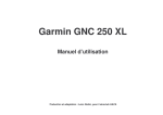
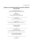
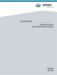
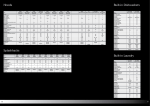
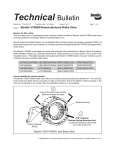
Recommended Relube Cycles for Universal Joint Kits SPICER® DRIVESHAFT LUBRICATION INTERVALS* SERIES CITY ON-HWY. LINEHAUL ON/OFF-HWY. 5,000/8,000 mi (8,000/12,800 km) or 3 Months (whichever comes first) 10,000/15,000 mi (16,000/24,000 km) or 3 Months (whichever comes first) 10,000/15,000 mi (16,000/24,000 km) or 3 Months (whichever comes first) 5,000/8,000 mi (8,000/12,000 km) or 3 Months (whichever comes first) Spicer Life Series® - Medium Duty (SPL-55, 70 & 100) Slip members are booted and permanently lubricated. 25,000 mi 40,000 km or 6 Months (whichever comes first) 25,000 mi 40,000 km or 6 Months (whichever comes first) 25,000 mi 40,000 km or 6 Months (whichever comes first) 25,000 mi 40,000 km or 6 Months (whichever comes first) Spicer Life Series - Heavy Duty (SPL-140) Standard Spicer Life Series® u-joint. Slip members are booted and permanently lubricated. 25,000 mi 40,000 km or 6 Months (whichever comes first) 100,000 mi 160,000 km or 6 Months (whichever comes first) 100,000 mi 160,000 km or 6 Months (whichever comes first) 25,000 mi 40,000 km or 6 Months (whichever comes first) 350,000 mi 560,000 km or 3 Years (whichever comes first) 100,000 mi 160,000 km or 1 Year (whichever comes first) Spicer® 10-Series™ (1480 thru 1810 & SPL-90) Slip members also require lubrication. Relubrication cycles vary depending on the service requirements and operating conditions of the equipment. Chart 4 shows a recommended lube cycle for various types of service. Lubrication Procedure for 10 Series Slip Assemblies Relube slip assemblies at the same intervals as universal joint kits. Apply grease gun pressure until grease appears at the pressure relief hole in the slip yoke plug. (See Photo 2) Cover the hole in the plug with your finger and continue pres-sure until grease appears at the slip yoke seal. (See Photo 3) LUBRICATION SPECIFICATIONS UNIVERSAL JOINTS J3299-3-DSSP JANUARY 2012 SPICER LIFE XL® - FIRST LUBRICATION CYCLE* Spicer Life XL® - Heavy Duty (SPL-170XL, & 250XL) Extended Lubrication u-joints. After initial miles (kilometers) or time is reached, the joints must be relubricated. Slip members are booted and permanently lubricated. 100,000 mi 160,000 km or 1 Year (whichever comes first) 350,000 mi 560,000 km or 3 Years (whichever comes first) 25,000 mi 40,000 km or 6 months (whichever comes first) 100,000 mi 160,000 km or 6 months (whichever comes first) Photo 3 Important - In cold winter months, activate the slip spline assembly by driving the vehicle sufficiently to cause displacement of the grease prior to its stiffening. Otherwise, the slip yoke plug may be forced out due to hydraulic pressure causing loss of grease and allowing abrasive contaminants to enter the slip spline. SPICER LIFE XL® - RELUBRICATION CYCLE* Spicer Life XL - Heavy Duty (SPL-170XL & 250XL) Extended lubrication u-joints. Once greased, this relubrication interval must be followed. Slip members are booted and permanently lubricated. Photo 2 100,000 mi 160,000 km or 6 months (whichever comes first) 25,000 mi 40,000 km or 6 months (whichever comes first) *We require relubrication with Chevron Ultra-Duty EP-2 or a compatible lithium based grease meeting N.L.G.I. Grade 2 specifications as well as ASTM D4950 "LB" specifications. The SPL slip assemblies are lube for life and do not require greasing. Any damage to the boot or loss of a boot clamp will require the old boot to be removed and a new boot kit installed. Follow the proper procedure for cleaning the yoke shaft and slip sleeve before adding new grease. This procedure can be found in service manual 3264-SPL. Note: The boot kits have the proper amount of grease in every kit, it is not necessary to add additional grease. Recommended Lubricants for Slip Assemblies Always use a good E.P. grease, meeting N.L.G.I. Grade 2 specifications, on Glidecoat™ and steel splines. The same lubricant used for universal joint kits is satisfactory for slip assemblies. Lubrication Procedure for Non Self-Aligning Center Bearing Assemblies NOTE: We recommend that all driveshafts be inspected for wear and damage every time the vehicle is serviced. This includes any scheduled and/or unscheduled maintenance that occurs within the driveshaft lube intervals. City is defined as all applications that require a minimum of 90% of operation time within the city limits. On-Highway is defined as all applications requiring less than 10% of operating time on gravel dirt or unpaved roads. Linehaul is defined as 100% of operation time on smooth concrete or asphalt. On/Off-Highway is defined as all applications operating primarily on paved roads, but requiring more than 10% of operating time on gravel, dirt or unpaved roads. We recommend genuine Spicer® Dana Holding Corporation Aftermarket Group PO Box 321 Toledo, Ohio 43697-0321 www.spicerparts.com J3295-3-DSSP 10/11 © Dana Holding Corporation, 2011 Initial lubrication is done by Spicer manufacturers. (No attempt should be made to add or change grease within the bearing itself.) However, when servicing a driveshaft in the field with a new center bearing, it is necessary to fill the entire cavity around the bearing with waterproof grease to shield the bearing from water and contaminants. The quantity should be sufficient to fill the cavity to the extreme edge of the slinger surrounding the bearing. Lubricants must be waterproof. See Recommended Lubricants for Center Bearings, below. Lubrication Procedure for Self-Aligning “XC” Center Bearing Assemblies The XC self aligning center bearing does not require any lubrication within the bearing or to the bearing outer surface due to the maintenance-free double lip seal bearing. Recommended Lubricants for Center Bearings Rylon Premium No. 3 Source: Amoco Oil Company Amolith 8516 Source: Amoco Oil Company Van Talgar No. 4 Source: Exxon Company © Dana Holding Corporation, 2011 Supersedes J3299-2-DSSP Dated June 2008 LUBRICATION SPECIFICATIONS Lack of proper lubrication is the most common cause of premature failure of universal joint kits and slip assemblies. Properly sized Spicer U-joints that are adequately relubricated at recommended intervals will normally meet or exceed fleet operational requirements. Inadequate relube cycles and failure to lubricate the joints and slip spline properly not only cause joint failures, but lead to other problems such as slip spline seizures. Proper relubrication flushes the U-joints and removes abrasive contaminants from the U-joint bearings. Warning - Inadequate lubrication can cause driveline failure which can result in separation of the driveline from the vehicle. A separated driveline can result in serious injury or death. In order to avoid driveline failure, including driveline separation, you must: 1) Carefully review the lubrication specifications in this manual. 2) Be sure that you use only approved lubricants. 3) Be sure that you relubricate at recommended intervals. Lubrication Procedure For Universal Joints Spicer replacement universal joint kits contain only enough grease to provide needle bearing protection during storage. It is therefore necessary to completely lubricate each journal cross and bearing assembly prior to assembly into the driveshaft yokes. Each journal cross lube reservoir should be fully packed with a grease as recommended in Chart 4. Each bearing assembly should also be wiped with the same grease, filling all the cavities between the rollers and applying a liberal grease coating on the bottom of each bearing cap. After the kits are installed into the driveshaft yokes and prior to placing into service, relube as follows: Warning - Rotating shafts can be dangerous. You can snag clothes, skin, hair, hands, etc. This can cause injury or death. Do not go under the vehicle when the engine is running. 10 Series Driveshaft - Full Round Closed Yoke Holes On 10 Series full round closed hole yokes, Figures B &C, loosen the bolts holding the bearing assembly that doesn�t purge to release seal tension. It may be necessary to loosen the bearing assembly approximately 1/16 inch minimum. Apply grease gun pressure to purge seal or seals. If loosening does not cause purging, remove the bearing assembly to determine cause of blockage. Re-tighten or replace bolts based on bolt designs as detailed in Chart 2 or 3. 10 Series Driveshaft - Serrated Bolt with Lock Patch (Full Round) SPL Series Driveshaft Apply grease gun pressure and purge all four bearings until fresh grease is seen at all four bearing seals. 1. If a bearing will not purge, apply pressure to yoke lug ear opposite of non-purging bearing while grease gun pressure is being applied. This should firmly seat the ujoint against the cup seal and relieve seal tension of nonpurging bearing. See Warning, below. Repeat procedure for any other non purging bearings (See Photo 1) Warning - To prevent serous eye injury, always wear safety glasses when performing maintenance or service. Failure to wear safety glasses could result in serious personal injury, and /or partial or complete vision loss. The self-locking design (Figure B) for full-round yokes uses serrated bolts with lock patch and DOES NOT require a lock strap (as in Figure C). When re-installing this type, it is important that the old serrated bolt be replaced and the new bolt torqued to the proper specifications. Re-Installing Serrated Bolts: Loosely install new bolts. (See the following chart below for bolt part numbers.) Tighten the new bolts to the torque specified in Chart 2. See Warning 1. Using the proper lubricant, purge all four bearing seals of each U-joint. This flushes abrasive contaminants from each bearing and assures all four bearings are filled properly. *Purge the seals. Spicer seals are made to be purged. 2. If any of the seals fail to purge, move the driveshaft from side to side while applying gun pressure. This allows greater clearance on the thrust end of the bearing that is not purging (Photo 1). 3. Because of the superior sealing capability of the Spicer Seal design on the 1610, 1710, 1760, 1810, 1880, SPL140, SPL170 and SPL250 Series, there will occasionally be one or more bearing seals of a U-joint that may not purge. Release seal tension using the following seal tension release procedure: * Note: Purge - The point at which fresh lubricant has flowed from the seal. Quick Disconnect (Half Round Yoke) On Quick Disconnect“ half round end yokes , Figure A, remove the U-joint from the yoke, while insuring cup will not disengage from u-joint cross, while grease gun pressure is being applied. Reinstall the U-joint Kit, with new bolts in the yoke, and torque to the specs shown in Chart 1. SERIES BOLT P/N SPL90 SPL140 SPL170 SPL250 1610 1710 1760 1810 6-73-412 .375-24 5007417 M12x1.25-6g 5007417 M12x1.25-6g 5007417 M12x1.25-6g 6-73-412 .375-24 8-73-316 .500-20 8-73-316 .500-20 8-73-316 .500-20 Chart 1 THREAD SIZE BOLT TORQUE (LB-FT) (NM) 45-60 61-81 115-125 156-169 115-125 156-169 115-125 156-169 45-60 61-81 115-135 156-183 115-135 156-183 115-135 156-183 Figure A Warning - Half round bearing strap retaining bolts should not be reused. Photo 1 Figure B 2. If this procedure does not allow purging from targeted cups, attempt to relieve seal tension by one of the following procedures: Figure C For full round or inboard bearings, remove spring tab from non purging cup and apply pressure in opposing direction to cup that will not purge to attempt to relieve seal pressure while grease gun pressure is being applied. Torque Specifications 10 Series Driveshaft - Bearing Plate Bolt Torque Serrated Bolt Style Non-Serrated Bolt Style SERIES BOLT P/N BOLT TORQUE (LB-FT) (NM) SERIES 1610 1710 1760 1810 1880 Chart 2 5-73-709 6-73-209 6-73-209 6-73-209 7-73-315 26-35 38-48 38-48 38-48 60-70 1610 1710 1760 1810 1880 Chart 3 THREAD SIZE .312-24 .375-24 .375-24 .375-24 .438-20 35-48 52-65 52-65 52-65 81-95 BOLT P/N THREAD SIZE 5-73-109 6-73-109 6-73-109 6-73-109 7-73-115 .312-24 .375-24 .375-24 .375-24 .438-20 BOLT TORQUE (LB-FT) (NM) 26-35 38-48 38-48 38-48 60-70 35-48 52-65 52-65 52-65 81-95 Warning - Failure to properly tighten bolts, and reuse of serrated bolts, could cause the driveshaft to loosen and separate from the vehicle or machine, which could cause loss of control and could result in serious personal injury or death. Retightening of Bolts: Lock Strap Design. After lubricating the joint, run the bolts down until the bearing plates are flush to the yoke faces, torque bolts to specification shown in Chart 3 and then bend the tabs of the lock strap against the side of the bolt heads to lock the bolts in place. See Warning For ß round or outboard bearings loosen bearing retainer from non-purging cup, insuring cup will not disengage from u-joint cross, while grease gun pressure is being applied. If all four bearings, purge fresh grease, replace removed spring tab and spring bolts and any loosened retainer bolts with new. Follow procedure in service manual 3264-SPL for re-installation. 3. If the bearings still do not purge, complete removal of the universal joint kit is needed to determine cause of blockage. See service manual 3264-SPL for proper removal procedure.