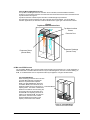
1
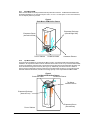
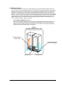
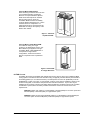
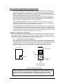
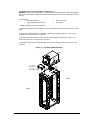
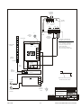
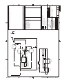
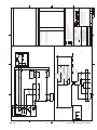
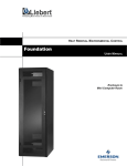
7.0 Troubleshooting
7.1 GENERAL TROUBLESHOOTING
Troubleshooting the MCR is similar to troubleshooting other Liebert environmental systems, except that the
cooling systems are installed in a self-contained rack. The information below describes various symptoms a
user may encounter in the event the Foundation MCR™ develops a problem. Use this information to
determine whether external factors cause the problem and how to remedy the situation.
SYMPTOM: ECM IS NOT COOLING OR CABINET IS HOT
1. Check if the condenser coil is clogged or needs cleaning. (See Periodic Maintenance, section 4.0).
2. Check clearances around cabinet. Check that the unit has at least one foot of clearance in front of,
behind and above the cabinet, and that the condenser airstream is not compromised. Make sure that the unit
is not directly beneath a heating duct. If the unit is installed in a closet, alcove, or enclosed area without
building ventilation, a heat rejection option may be required to move rejected ECM heat out of the confined
area.
3. Verify that the evaporator discharge and return is not blocked. Check for airflow obstructions inside the
bottom of the cabinet such as manuals, cables, etc.
4. Confirm that the ECM is connected to the proper electrical service. The internal evaporator airflow fan
will operate whenever the ECM is receiving AC power. The evaporator fan will continually circulate internal
air through the cabinet, even when the compressor has cycled off. If the evaporator fan is not running, verify
that the unit is connected to the proper electrical service. (See Electrical Service Requirements, section 5.0).
Removing and Re-applying Power: The ECM compressor is protected by a 2-minute time delay relay. If
power is removed while the refrigerant circuit is operating, 2 minutes must pass before the refrigerant
circuit will restart. Two minutes after power is restored & if the internal temperature is above 75oF
(23.8oC), the cooling circuit should restart. Longer delays may indicate an internal ECM fault.
5. Check for open doors, and gaps in side panels or cable entrance points. Direct ambient heat
loading through an open door, or cable entry points etc. can overload the ECM. See item 1, next page.
6. Verify that the ECM or BCM Control Cable is Installed. The ECM control cable must be installed on the
rear of the ECM in order for the ECM to provide cooling. The control cable also interfaces the ECM with the BCM
and High Temperature Alarm Module when these options are installed.
7. Verify that the ECM is not overloaded. ECM1000 series should be matched to a combined total UPS
and equipment load of 1000VA or smaller (up to 824W), the ECM2000 series should be matched to a
combined total UPS and equipment load of 1000VA to 2000VA (up to 1647W). In multiple ECM
configurations, the load should be distributed according to the capacity of the ECM in each cabinet.
8. Check positioning of equipment inside the enclosure. Equipment dissipating the most heat should be
located as close to the ECM as possible. To promote proper airflow patterns, any unused rack space should
be at the end of the rack that is opposite the ECM. Check for open spaces between rack-mounted equipment
that may be short-cycling the ECM airflow; advise the user of the need to reposition any equipment in order
to enhance internal airflow.
9. Check exhaust ducts for proper airflow. Directly connected heat rejection ducts must include fans or a
booster blower with the capacity to overcome the static pressure in the duct. The ECM’s condenser fan is not
designed to overcome the static pressure of an external exhaust duct. The discharge from two or more
cabinets should not be routed into the same duct unless the blower has been sized with enough capacity to
overcome the combined total static pressure of each duct.
SYMPTOM: HIGH TEMPERATURE AUDIBLE ALARM AND BACK-UP COOLING MODULE IS OPERATING
The HTAM (High Temperature Alarm Module) is located on the top/left of the frame (facing the rear of the
cabinet) and can be accessed through the rear door of the cabinet. The Alarm Silence button is located on
the HTAM. If the cabinet is NOT generally hot, check if the HTAM sensor is located in a hot spot, such as
near the exhaust of a server or above a monitor. The sensor is permanently connected to the HTAM via a 2’
(61cm) white cable. The sensor can be relocated to detect a more average temperature location. If the
sensor is not located in a hot spot, check the "ECM not Cooling" symptom above.
Mar 2004
- 14 -
Liebert Foundation MCR Service Manual