1
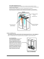
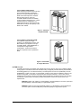
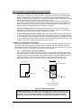
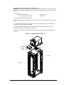
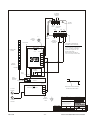
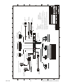
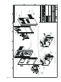
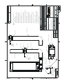
7.3
Investigating ECM Failure
7.3.1 Electrical Connections
Confirm that the ECM is connected to the proper electrical service. The ECM is not equipped with an
on/off switch or control panel. The evaporator fan will continually circulate internal air through the
cabinet, even when the compressor has cycled off. If the evaporator fan is not running, verify that the
unit is connected to the proper electrical service as described in section 5.1. The ECM should not be
powered from the internal UPS, as it will cause UPS overload and shutdown.
The ECM control cable must be installed on the rear of the ECM in order for the ECM to provide cooling.
The standard control cable connector supplied with the ECM includes an internal jumper between pins 1
and 2 and an extended cord providing connection between pins 3 and 4. Refer to the CON1 connector in
the ECM Schematic, Fig 8.2. The jumper between pins 1 and 2 is required to energize the compressor.
The extended cord provides 24 VAC to the optional High Temperature Alarm Module, if installed.
The compressor is protected by an integral overload sensor (there is no external reset) and a 2-minute
time delay relay, refer to the ECM Schematic, 163777. If the compressor is not running, but power is
available and the control cable is connected, the ECM will need to be removed from the enclosure for
troubleshooting. The thermostat, time delay relay, and R1 should be individually checked for continuity.
7.3.2 Removing the rack-mount ECM from the Enclosure
Tools required:
10mm or 11/32 socket and drive
long (6”) Phillips tip screwdriver
small wire cutters
1. Unplug the ECM from the electric source.
2. To access the ECM, open the front door of the Foundation MCR and remove the two retaining bolts
from the inside of the front access plate, located at the bottom of the rack. See diagram under Periodic
Maintenance, section 4.4. The bolts require a 10mm socket, and are held in the frame by retaining clips
to prevent them from falling inside the unit. The plate will swing down freely once the bolts are removed.
3. On 38-inch deep enclosures remove the condensate drain extension tube from the retaining bracket at
the rear of the unit. On 30-inch deep enclosures, there is no extension tube on the condensate drain.
4. Disconnect the ECM Control Cable from the rear of the ECM and cut the wire ties to free the control
cable.
5. With the long phillips tip screwdriver, remove the 4 screws from the ECM mounting brackets and
remove the brackets from the enclosure.
6. Carefully remove the gasketing at the bottom front of the frame. Retain the Presstite insulation tape for
re-installation. The ECM will now slide out the front of the enclosure.
Mar 2004
- 17 -
Liebert Foundation MCR Service Manual